HOLIDAY DONATION DRIVE - SUPPORT MSW - DO YOUR PART TO KEEP THIS GREAT FORUM GOING! (Only 53 donations so far out of 49,000 members - C'mon guys!)
×


ianmajor
-
Posts
784 -
Joined
-
Last visited
Content Type
Profiles
Forums
Gallery
Events
Everything posted by ianmajor
-
 A tip that technology lecturer gave me related to using thin super liquid glues to fix metal to wood. The problem is the wood tends to rapidly draw the glue away from the joint by capillary action. His answer was to dampen the joint area of the wood with water, put the super glue on the metal surface then make the joint. It has worked well for me. Ian M.
 -
B.E. That is excellent. I will go with that ie 4 on the foc'sle and 8 on the quarter deck. Thanks again. BTW. I should really have turned my own barrels up but have opted to order some Caldercraft barrels. They are 1:64 which means that they will be about 2mm too long for 1:75 but I am hoping this will not be too obvious when they are fitted. Ian M.
-
B.E. Thanks for the reply. I am making the 1748 HMS Unicorn (using the Coral 1:75 kit) which according to the information I have pulled together had 24 nine pounder cannon on the upper deck, 4 three pounder cannon of the quarter deck and 12 half pound swivel guns. (Corel don't supply or document the swivel guns.) I think the swivels mounted as per the 1740 ship would give me 10 of them with six mounted on the quarter deck which leaves me two short. Although the Unicorn seems to have been a bit of an oddball a contemporary model of a 1740 ship would be a good guide for me. Which model is this? Looking at the plans that Chuck has produced for Winchelsea - which is a larger development of Unicorn/Lyme I am happy about the position of 10 of the swivel guns. All good historical research generates more questions than answers! BTW. I am enjoying your Pegasus build log which is giving me inspiration and some excellent input to my model. Ian M.
-
Garward, The judges are making a very careful examination of the documentation. Is it a requirement of the competition that full supporting documentation is presented with the model? Ian M. PS Congratulations on the silver.
-
Wow. That is a scary level of examination. I think I would insist they put on blindfolds before looking at my models! They look very impressed with the standard of workmanship - and so they should. Ian M.
- 111 replies
-
- 1
-

-
- le fleuron
- cannon
- (and 1 more)
-
I am trying to determine where the foremost two swivel guns are fitted on a mid 18th century British frigate which has a beakhead bow. I can find plenty of pictures showing those on round bows where they are fitted side by side on the knightheads(?). In this position they are readily accessible from the foredeck. However the knightheads on a beakhead bow appear to me to be in an inconvenient position for any hostile action hence an unsuitable location for the two guns. Can anyone clarify the positioning of these guns for me? Ian M.
-
Wefalck's advice about using ex aerospace/printed circuit board industries is good. I would take care about other cheap supplies of drills - they may be rejects. I have had some "unfortunate" experience in this area. The bits did not run true and drilled over size holes. When I examined them under a jewellers lense I found they had their tips ground off centre. They would certainly have ruined work on this small scale. Ian M.
-
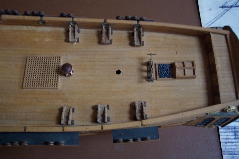
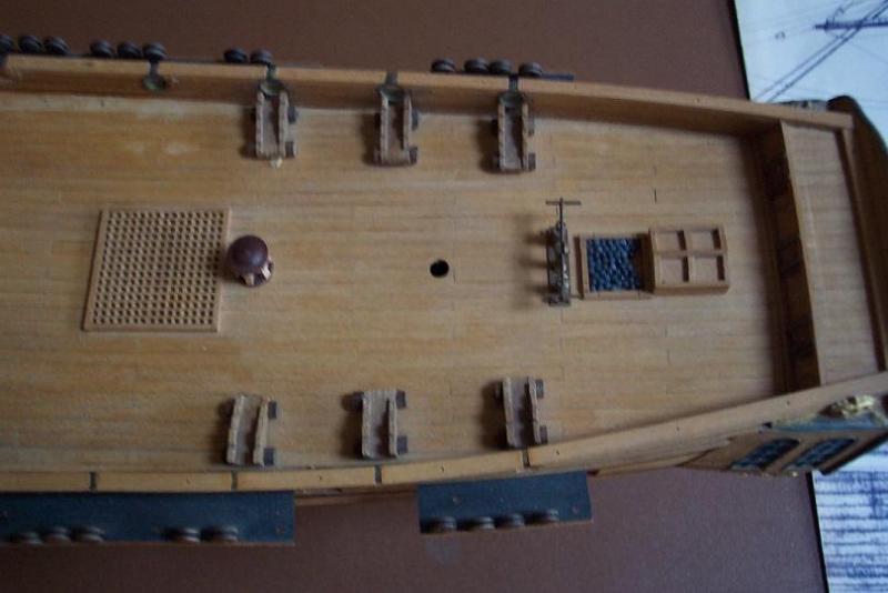
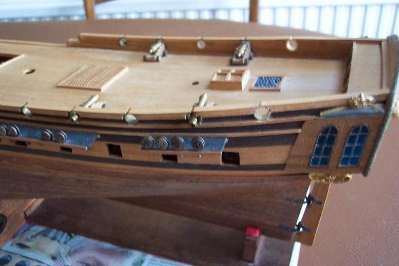
Following Mark's comments I decided to add the two extra ports on the quarter deck. All the info I have seen on the Unicorn show 5 on each side though the kit only supplies the brass sorround rings for 4 per side. So out came the mimi lathe and I turned a couple of extras up out of brass rod. Dimensions are: Outside diameter 9.5mm Inside diameter 7.0mm Width 4.2 mm. I also put a 30 degree taper on the first millimeter and rounded the edges with a file to match the original kit versions. Then to fit them. The bulwarks have been in place for 30 years and they didn't take kindly to being disturbed - tending to split. I was hoping to ream the holes as previously but this proved too destructive. So I had to resort to half round swiss files. At the same time I removed 4 of the gun carriages from the quarter deck. The ship now has 28 cannon in total. The carriages had been glued to the deck with 2 part epoxy. Fortunately they were easily prised away leaving small pads of glue which I gently shaved off with a small chisel. I had not been happy with the position of the pump and lantern which were fitted as per the instructions. The contemporary diagrams show the lattern over the captain's cabin and the adjacent ante room, not over the wardroom as modelled (the wardroom has the rear windows for natural light). So off came the pump and the lantern. The former left a little damage but the latter ripped parts of 5 deck planks away. Out came the small chisel to plane the remains of the damaged deck planks away and new ones replaced them. The lantern is now fitted where the pump had been. I have considered fitting the pump on the upper deck just in front of the main mast but it would be all but invisible there so I don't think it worth fitting. Two photos: The first shows the before situation - I had already removed two of the carriages. The second shows after the work with the pump gone, the lantern in its new position plus the two (nice and shiny) new ports. Now just 4 cannon on the quarter deck.
-
Mark, Thanks. You have confirmed my vague recollection of the Chapman diagram. I saw a copy in a bookshop in Zagreb way back in 1976. I had a sneaky read but did not buy it. Time to get the mini lathe out and turn a couple of extra port surrounds. There are diagrams of the Lyme on the NMM web site (see plan the web page shows the body and upper deck - useful). The Lyme had 6 ports on each side of the quarter deck. There were other differences between the two ships. I agree about the first port threatening the rigging. I constructed most of the hull as per the instructions. This also lead to a couple of cannon having deck supports close behind - first recoil and down comes the deck above! I don't think the captain has been around for a while. That deck is filthy!

-
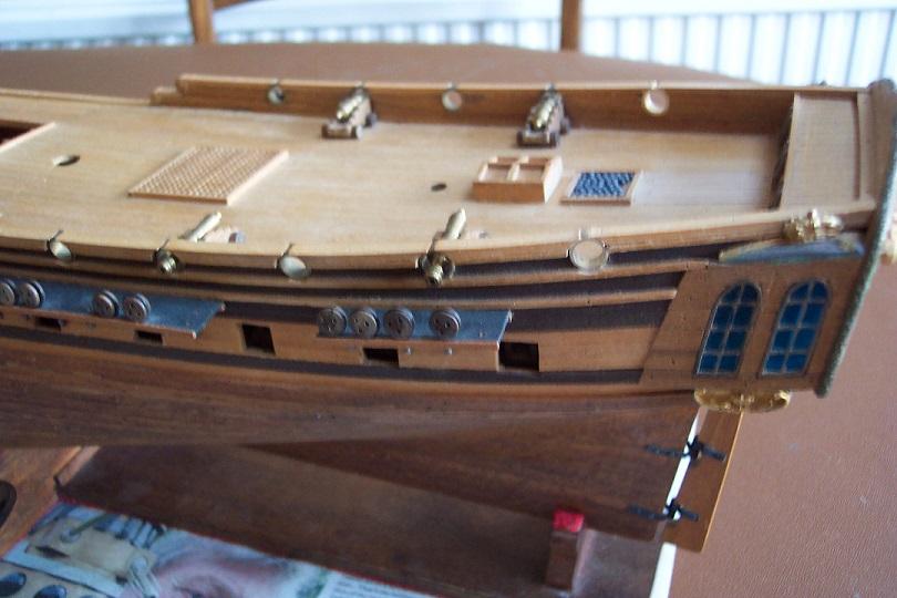
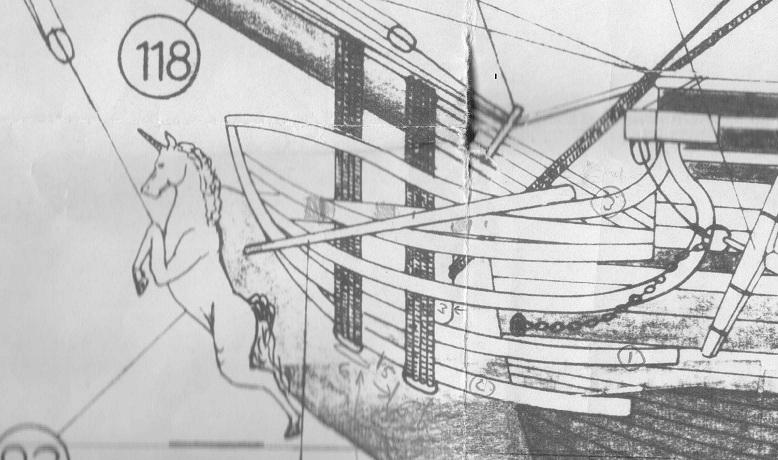
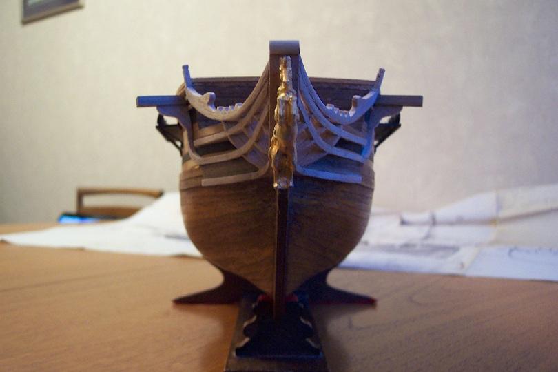
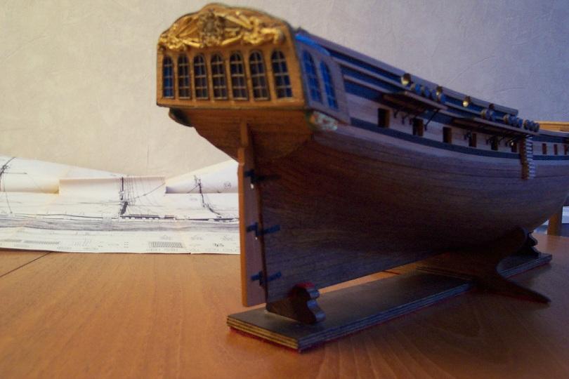
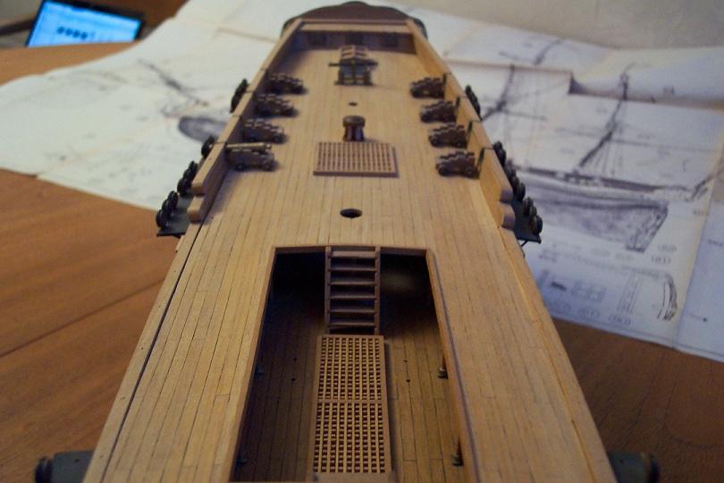
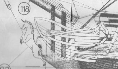
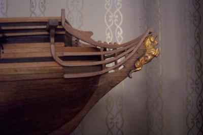
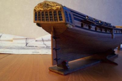
An area I struggled with was the head. The plan and side views on the diagram didn't agree and at the time of construction the only photo I had was a view of the bow of Victory in a book on the life of Nelson. The result looked like a lorry cab stuck on the body of a small sportscar - very front heavy. I had fitted all 5 of the horizontal rails but after some thought decided to reduce it to 4. I removed the lowest one - which was at or below the waterline anyway. I decided against rerouting the others due to high risk of damage. Where the fifth one was attached can be made out - the area needs restaining to fix. Below is a scan of the appropriate part of the diagram. The upper part of the head is show first curving up then back down towards the figure head - made me think of a blue whales mouth. I had not seen a picture of an actual ship showing this particular shape before (and have not since) so decided to fit it with a constant upwards curve towards the figure head. Hopefully this will be clear from the pictures below. Scan of plan. Close up view of head area on model. A previous contributor warned of using tools on wood that had been previously been used on metal - particularly steel. The second picture shows the rail that sweeps up to the derrick. The sharp curve is made from 4 pieces of wood. One joint can be seen as a black line from just such a cause. Another source of staining on there is where the pins supplied with the kit came in to contact with white PVA glue. I used these pins to hold some parts in place. Where the pins came in to contact with the wood a black mark was left. This could of course be turned to advantage by representing tree nails - though there are easier ways! The row of "teeth" on the top rails are each one piece. They will locate the booms between the middle "teeth". They were quite easy to produce. I took two 3x3mm pieces of beech and clamped them together in a machine vice. I then drilled 5 off 1.5mm holes 6mm apart centred on the join between the two pieces. I then openned them gradually to 5mm diameter. The two pieces were then seperated and cut to length. These rather delicate items were immediately glued to the upper rails and when dry the teeth were rounded with a file. I had previously drilled the two holes for the anchor chain but these were not in the right place, so I planked them over with some mahogany and will redrill. That area is thickened on the actual ships anyway. The next picture is looking head on. As can be seen it is bit asymetric. Below the bow planking there is a solid chunk of wood on each side of the keel piece. These had to be shaped from rectangular blocks. Sadly the port block has a slight attack of the mumps. Of course the effects of a small error at the early stages tend to grow into larger errors as more parts are added on top. The next view is of the stern. The castings above and below the side gallaries had to be filed down to about 2/3rds their original size to fit. The lower ones were too long, the top ones were too wide. The lower ones still overhang to the rear, not sure if this is correct or not. This left some gaps which I filled with Squadron Green Putty which is still showing green awaiting final paint touch up. The window frames require a paint touch up as well. The final view is along the deck. The deck planking has had black pencil rubbed allong the plank edges. This has been slightly hidden by dust. A chase along the joints with a propelling pencil lead before final varnish should sort this. The keen eyed amongst you will notice that the deck planking joints line up on every other row rather than every third or fourth. It comes from copying the planking of the floor under my carpet! There are 8 cannon towards the stern. There should only be 4 (and they should be smaller than those on the upper deck). I am trying to pluck up courage to remove 4 of them - though which 4?. The pump is fitted towards the rear as per the instructions. It should really be ahead of the main mast on the upper deck - and should be a chain pump. I don't fancy trying to lift it though. It is firmly attached to several deck planks. Well hopefully that is the last of looking back. Now to try and make some progress.


-
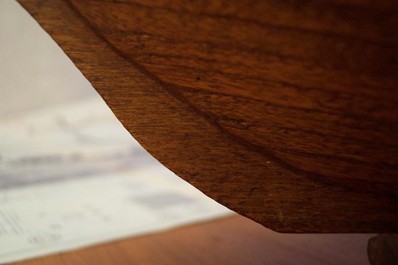
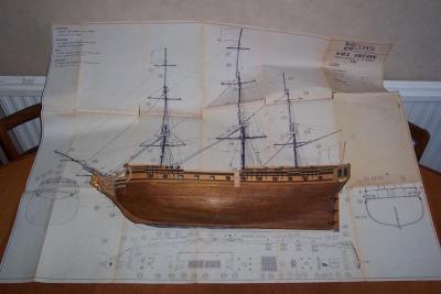
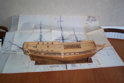
Time for some more photos of previous work The following shows the hull viewed low down on the port side. The hull is placed on the plan to give an idea of the scale of the rigging. This is a close up of the keel at the bow. You can probably tell there is no rabbet (I didn't know about such things at the time ). Some months after the planking was completed the leading edge of the planks started to spring out leaving a gap. I resorted to wallnut stained wood filler to fill the gap then sanded the ends of the planks to taper down to the keel. When I subsequently stained the planks the wood filler became pretty well camoflaged. It only really shows if you get close up.

-
Information on the Unicorn from Wikipedia. A history and some detail of the Unicorn(s) can be found on Wikipedia. Wikipedia as with any paper encyclopedia is a secondary source of information so should be treated with some care. Thus far the entries on the British frigates appear accurate. A list of frigate classes can be found at http://en.wikipedia.org/wiki/List_of_frigate_classes_of_the_Royal_Navy. When I looked through this information the questions started to outnumber the answers! The kit instructions describe the ship in question as a British 32 cannon frigate designed by F.H.Chapman in 1700(!). The date on the model plans is 1762. The source of plans for the hull is Chapman's book "Architectura Navalis Mercatoria" published in 1768. In this book he documents but is not the source of the designs. Unicorn was used as the name of several ships. The first Unicorn of this period was a member of the Lyme class.There were two ships in the class both built 1748. They were originally designated as 24 gun 6th rate frigates but they were later redesignated as 28 gun. This Unicorn seemed to have had a relatively quiet existence and was scrapped in 1771.This is the subject of the Chapman plan. More info on this Unicorn can found at http://en.wikipedia.org/wiki/HMS_Unicorn_(1748) The significance of the Lyme class members is that they were considered to be the first true frigates built for the British Navy based on the French privateer Tyger. The next Unicorn was a 1776 Sphinx class 20 gun post ship. The other Unicorn of this period was a member of the Pallas class built 1794. It was a larger 32 gun fifth rate frigate.It was scrapped 1815 having had a much more eventful existance than the previous ships. See http://en.wikipedia.org/wiki/HMS_Unicorn_(1794) . None of the above map directly on to that portrayed in the kit and I am left wondering whether it is an amalgum. Certainly to my eyes the kit's continuous fore/quarter deck looks too modern for a mid 18th century ship.If I were to be restarting this model I would change that deck. ...and from the National Maritime Museum There are photographs of a model of the frigate Lowestoft (or Lowestoffe) in the National Maritime Museum collection. I am using these in conjunction with the Petersson book to produce my rigging schedule. See http://collections.rmg.co.uk/collections/objects/66300.html .This Lowestoft is the 1761 32 gun frigate so is slightly larger. The previous Lowestoft was a 28 gun copy of the Lyme class which sank in 1760. Some points that I have noted from the Lowestoft rigging which I intend to feature in the Unicorn: 1) The mizzen mast is lateen rigged. I need to work out how this is done! 2) Only the main and fore yards have provision for stu'n sails 3) No dolphin striker
-
Sarah, Thanks for the compliment. I think this kit makes up to a very attractive model. There have been adverse comments in the past about the accuracy of the kit, but I believe with the research material available on the Web it is possible to improve on the model if that is what is required. It sits on a cabinet in my lounge and even without the masts and rigging it is a favourable talking point. Ian M.
-
Mark, Thank you for your kind words. The hull construction is two layers of planking on to plywood ribs. This gives a very strong construction - though I doubt the kit designer had my children's requirements in mind!
-
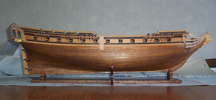
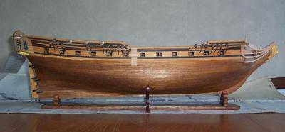
You have seen build logs for exceptional models on MSW - now for one from the opposite end of the skill spectrum! Brief history of the model to date. I have been working on this kit of the Unicorn on and off since 1975. It was probably one of the first sets produced since its diagrams are dated February 1974. The manufacturers “quantity surveyors” were obviously not up to speed evidenced by the shortfalls in some of the materials. For example, the kit supplies 32 cannon but included only 12 wheels for them, the material for planking the decks only covered two thirds of the upper deck let alone trying to cover the fore and quarter decks. The instructions were interesting. They were supplied in 3 different languages (OK), but there were three copies of the parts list all in Italian. From the logs that I have seen of later builds of this kit no mention was made of these issues so I assume it was an early life problem. The kit problems compounded by living long periods in hotels in a variety of countries as part of my work made progress very slow – in fact it ground to a halt. For some years the model became the base from which miniature Daleks could wage war or what ever it was my children were doing with it. Throughout these Inter Galactic Wars the ship demonstrated that she was a tough old bird sustaining very little damage. On my retirement I decided that I was going to produce some 7mm scale locomotives for each of my four children – you know the sort of thing – something to remember the old fool by. However my daughter basically said that I could keep my locomotives, she would much prefer “that old boat”. So construction restarted. I was in the process of fitting the deck furniture and preparing the spars ready for rigging when I decided to try to get an answer to a problem that had been confusing me for some time. This related to the rack that sits astride the jib (sorry guys – I did know its name from a previous posting – but I forgot what it was). In the kit diagram number 2 item 142 it is shown with 11 holes. The rigging schedule indicates 10 holes required. The plastic casting supplied has 9 holes. Doh! In searching for information I found build logs for two excellent renditions of this model which introduced me to MSW. Sadly I don’t know the names of the builders. I do hope their logs can be regenerated. I have copies of some of their pictures which I use for reference. What I found raised more questions in my mind than answers. I decided to maintain my “Lurker” status for a while whilst researching the job in hand and also learning the MSW etiquette. When I started I didn’t know my futtocks from my rat lines. Now at least I know that futtocks is not a naughty word. I have attached (I hope) two photographs of the model as is. The first is a view of the starboard side of the hull. The other Unicorn models had their hulls painted. Mine is "au naturelle" relying on the colours of the different woods supplied in the kit. The newer additions, all in beech, stand out having not been exposed to the elements. An example is the steps down the side of the hull which stick out like a sore thumb - compounded by their crude outline. The lower part of the hull is planked in mahogany. Over time this had faded from its original reddish brown to almost white so I used walnut wood stain to return its colour. I also stained the keel at the same time. Appart from that the other woods are untouched. So you can get an idea of what an unpainted model may look like after 40 years. I had painted the frames of the plastic windows gold but this needs refreshing. The decorative castings around the rear of the ship were far too big so I filed them down to their current size. They still overhang to the rear. There is some sign of corrosion around the castings but they should clean up OK before they are painted. I am debating with myself whether to paint the detail of this castings in reds and blues or to stick with all gold to match the rest of the "au naturelle" look. You may notice the poor old figurehead has lost the end of its horn. This was damaged before I received the kit. I will at a later stage amputate the rest and form a new brass one to be screwed in. The second view is looking down on to the deck. There is still evidence of long term dust around the cannon which I need to address. (Any views on how you keep a ship clean that is not in a glass case?) The two previous Unicorn build logs differed in their rigging. One using a modified schedule from the kit the other used the method given in the book “Rigging Period Ship Models” by Lennarth Petersson. I have decided to go with schedule based on the latter. I have now bought the book. It is a fascinating book in its own right. It documents the rigging of a contemporaneous model of the frigate Melampus. Strictly Melampus is a much later frigate than Unicorn so I should base my rigging plans on information given in “The Masting and Rigging of English Ships of War, 1625-1860” by James Lees but I I am afraid I balked at the £145 asking price on Amazon. The current position is that I need additional wood to make fittings for the proposed rigging. That is on order. My workship is being revamped so more work in ernest on the model should begin in a couple weeks starting with deck rings as per the Winchelsea plans. In my next posting I will pull together the information that I have gleaned for Unicorn including links to reference data. The historical information supplied in the kit can most kindly be described as fanciful! I will also offer my views on the accuracy of the kit plus any points around my model that may be of interest. Ian M.
-
MONTANES by Garward - OcCre
ianmajor replied to Garward's topic in - Kit build logs for subjects built from 1751 - 1800
Garward, This posting is excellent as is the quality of the model. Thank you for (re)sharing this with us. I am about to produce samson posts for my ship. What type of wood did you use? Ian M.