HOLIDAY DONATION DRIVE - SUPPORT MSW - DO YOUR PART TO KEEP THIS GREAT FORUM GOING! (Only 53 donations so far out of 49,000 members - C'mon guys!)
×


ianmajor
-
Posts
784 -
Joined
-
Last visited
Content Type
Profiles
Forums
Gallery
Events
Everything posted by ianmajor
-
 Juan, Very nice work. The choice of wood gives a beautiful look to the ship.
 -
What do you use your mill for ?
ianmajor replied to captainbob's topic in Modeling tools and Workshop Equipment
Bob, I use my milling machine for a whole raft of things both in milling and drilling jobs. The x-y table is a real bonus where you can, for example, drill an accurate pattern of holes, you can mount a blunt pin in the chuck and use it to press quite quickly an accurate pattern of cosmetic rivets. Using collets it is much easier to drill small holes (below 1mm dia) than using some form of hand drill - I break fewer bits with my mill - I adjust the x-y table to the desired position then lock it to avoid lateral stress on the bit. For milling it is great for accurate rebates. Recently I used it to make a wooden jig to assemble a companion way ladder. This involved milling the wood to the correct width then cutting equally spaced slots at 45 degrees to hold the ladder treads. There is little that you can do on a mill that you can't do with hand tools but the mill makes the tasks a lot easier to do. For me it is one of the tools that I think "how did I cope without it?" -
Hamilton and Kutlu thank you for your kind words - and a "like" from BE as well. I am flattered and slightly embarrassed because my modeling efforts will never produce the great results that you guys do. Once the stove is complete it will be installed under the fore deck where it will be well hidden. Oh well - it is a fun little sub project to do.
-
Hrvoje, Thank you for your kind words. Having seen your build, to have a compliment about my detail is praise in deed. You may be interested in the fact that my Unicorn's keel was laid whilst I lived in Belgrade but all the hull planking was done whilst I lived in Zagreb - which of course is in Croatia. My Unicorn is well travelled!
-
Mario, Congratulations on completion of a beautiful model. I have taken away some very useful tips from you on detailing techniques - thanks for those. I also compliment you on getting the Union Flag the right way up despite the artwork on the kit box showing the flag upside down. Perhaps the manufacturer wanted to display a boat in distress on Windermere!
-
William, Once again - very nice. I have not managed to pluck up the courage to make my own cannon barrels - yet. An interesting point of comparison. I note that you use a three jaw chuck to grasp the dowel without apparently denting the wood. Whenever I did that I always got indentations in the wood. My own answer was to use a collet instead - or to turn up a collar with a longitudinal slit to hold the dowel.
-
Mark, Janos and ZyXuz, Thanks for your kind words. I think metal work of this sort is quite easy, especially when assembled with soft solder and an iron (OK as long as you are not trying to make something stressed like a live steam boiler). I find getting good results in wood much more challenging. Glues and paints - well they are just a black art to me!
-
Ed, Thanks for that.
-
Ed, Lovely work - and a fascinating observation you make about the line of the outboard planking against that of the upper deck. A question I have (and my apologies if you have addressed it before) is about your blackening the hinges. You appear to doing so with the hinges in situ. If so how do you stop the blackening fluid from bleeding in to the wood which would turn it blue?
-
William, Superb idea. Nice work.
-
Thanks Mike, I am better with metal than wood. When I was in the first year of secondary school we had woodwork lessons. My woodwork teacher was married to my Father's cousin. ("There's distinction" as my Welsh friends would say). In one lesson my teacher said in a loud voice that "No one so bad at woodwork could possibly be a relative of his wife". From year 2 on I did Latin instead. I wasn't very good at that either! Maths, Physics and Chemistry were my thing.
-
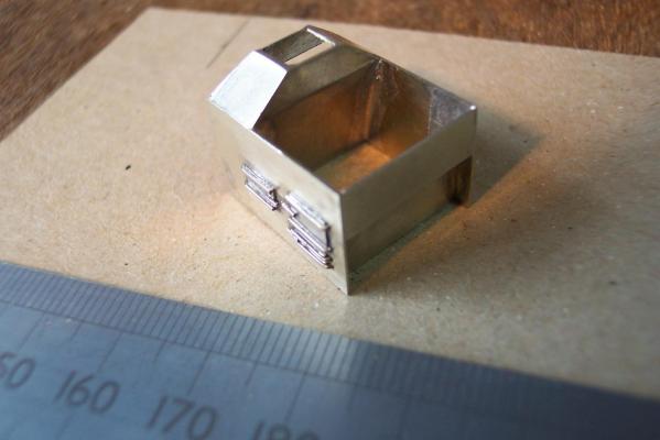
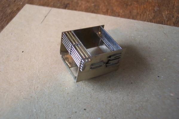
Before the boiler top is fixed on I can still access the inside of the stove. So I have made 2 cocks which will be soldered in place from the inside of the end plates. I have made some cocks from 3mm diameter brass rod, these were end drilled 0.5mm, then turned to the profile in the photo. They were also cross drilled to take wire handles. However I am not happy with these. Looking at photos of the replica stove on Victory the spouts should be longer and tapered. The left hand cock in the photo has also got an off centre hole. So I will replace these. Photo 10) I will soon be fixing legs on the stove. These will be made long so that they can fit in to holes in the brick base. I need to complete the brick base first so that I can determine how long the feet need to be. That is the current job in hand. Time to go back to the work bench.
-
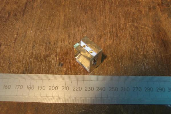
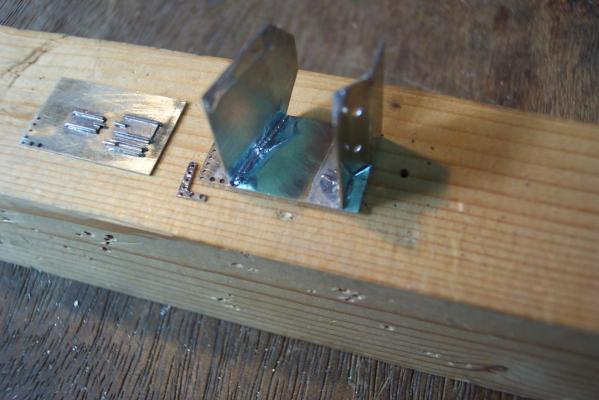
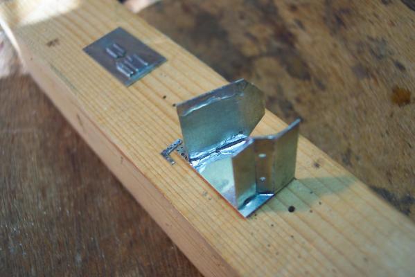
Next up was to solder the other side in place and create the hood. The rear of the hood was already in place but pointed backwards at too great an angle. So using the piercing saw I cut a grove along its rear face immediately above the sides. This allowed me to bend it cleanly upwards to the right angle. The front of the hood was cut from the strip used to make the cross pieces above. From the rear of the hood I measured the height for the hood side pieces, produced strip to this size and cut off two over length pieces. The hood sides were then soldered to the hood rear and the hood front soldered between them. This left the hood sides overlapping the front. It was simple job to file them back to the correct size. Photo 8) Next came the grate. I threaded 5 lengths of 0.5mm and 2 lengths of 0.75mm N/S rod though the stove sides - not forgetting the middle spacer. The rods were soldered in place on the outside of both sides. The middle spacer was then carefully positioned centrally and squarely. This part only needed flux applied, no extra solder, before the iron was touched on it. The solder still on its surface from the earlier stage flowed in to all the joints - leaving firmly in place and tidy. Photo 9 shows it before I trimmed the excess rod off. Photo 9)
-
I find it easier to attach some detail whilst the parts are flat. In this case I added the small doors on to the sides. I made all the doors from 0.25mm sheet N/S. They were all the same width so again I produced a strip of N/S to this width then cut the individual doors from it. The hinges and latches were made from 0.5mm N/N wire. These I attached to each door before separating it from the strip - it made it a lot easier to hold. I then ran a smooth file over the hinges and latch to make them flat. The completed doors were then soldered to the sides. The hinge/latch detail is a bit crude and cries out for etched brass overlays. Photo 5 shows (from left to right) The three parts to make the boiler end, the two sides with the middle spacer, the hearth end which includes the rear of the hood. Photo 5) Time to start soldering. Because no parts will come under any strain I am happily using soft solder. I have soft solders that melt just above 100 degrees C up to 230 degrees C for which my iron has plenty of grunt. I use liquid (acid) fluxes. I also have silver solders and a variety of blow torches for the heavy jobs. I soldered the cross pieces to one side. Purists say that you should fix one end to one side, fix the other end to the other side then bring the two assemblies together - but hey ho. Photo 6) Photo 7)
-
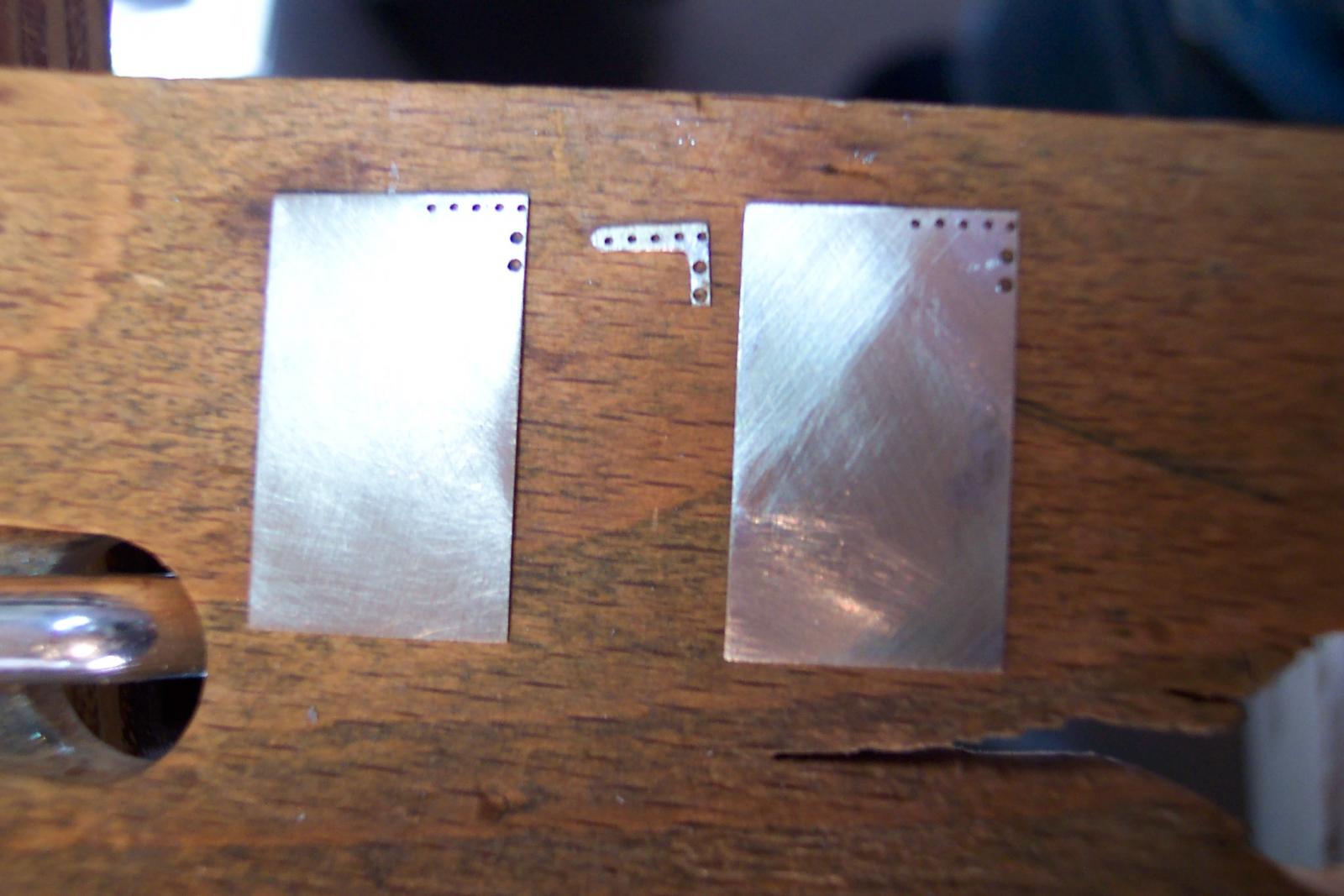
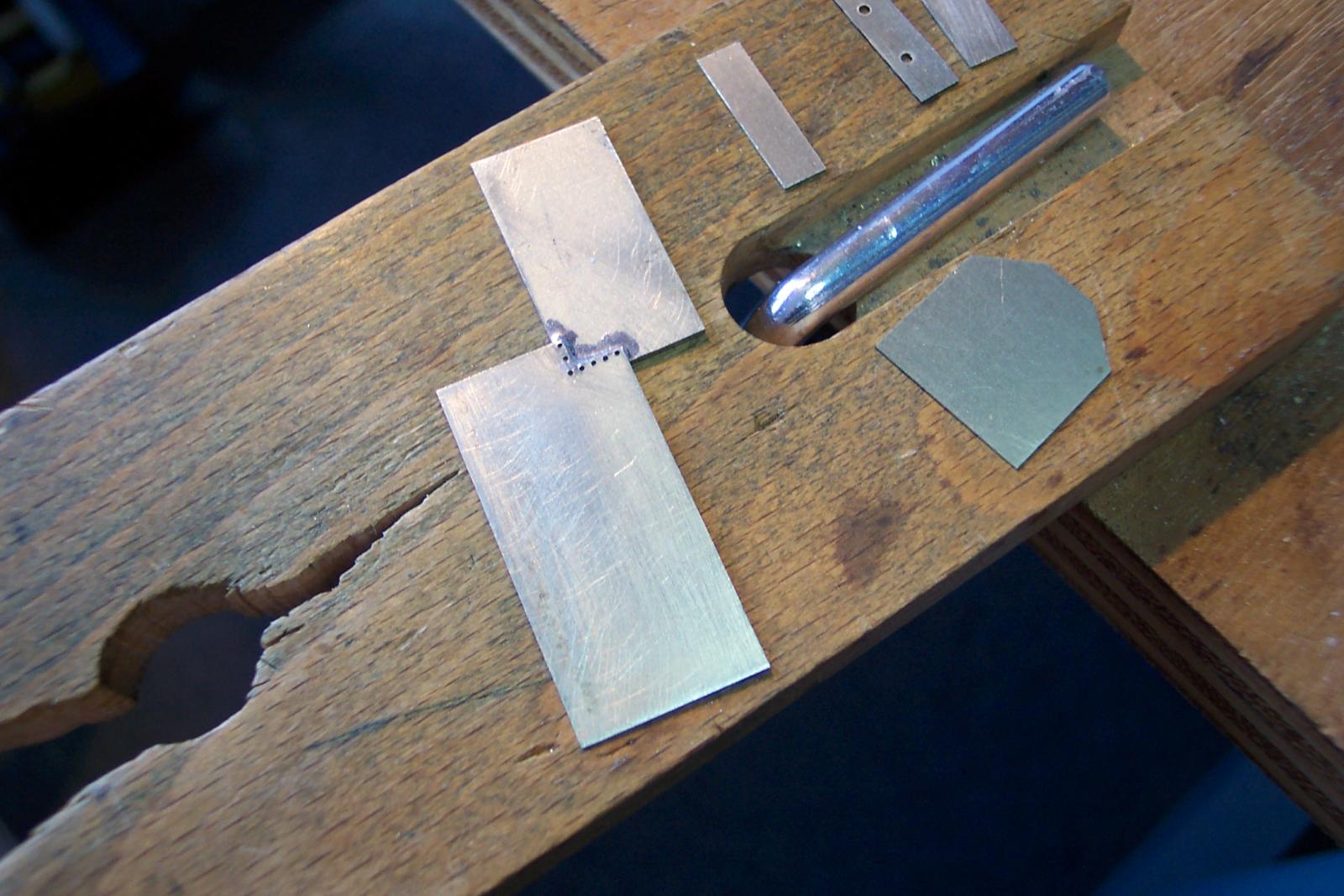
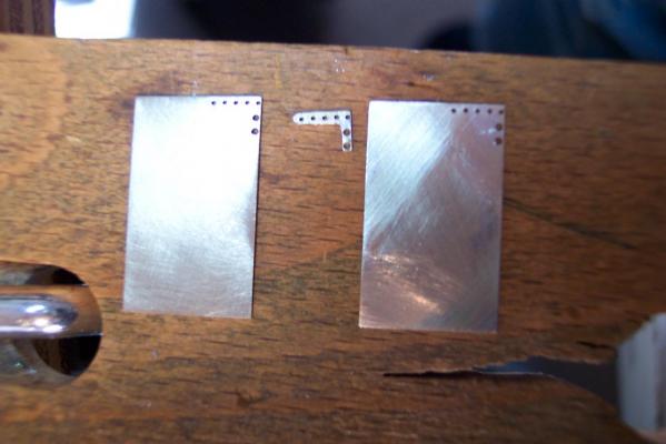
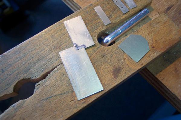
The excess on the top piece was cut off and the side pieces were filed to the correct length. This resulted in two side pieces and one small "L" shaped piece still solder together. Photo 3) The parts were then separated. Photo 4) You may notice that the photos of the parts are posed on my wooden peg and that I have cut little slots in to it. These cuts are actually deliberate. I use them to cut very small parts and also the stop the blade wandering from side to side when starting a cut on the edge of some sheet.
-
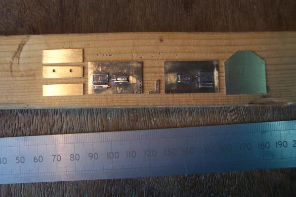
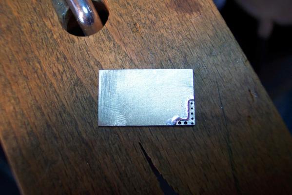
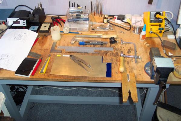
Most of the material for the model is nickel silver. I used 0.4mm sheet for the platework and 0.25mm sheet for detail, plus 0.5mm and 0.75mm diameter N/S wire. The photo shows the 0.4mm sheet ready for marking out. I have stopped using engineer's blue to coat the metal. Instead I use a permanent marker pen to give the blue area shown on the N/S sheet in the photo. I did virtually all the marking out with the Jennys (odd leg calipers) which are sat on the sheet in the photo. Photo 1) On this model the ends go between the sides so it is important that all the pieces that go across the stove are the same width. So first I cut a strip of N/S to that width and long enough to make all the parts. First step was to make sure the edge of the sheet N/S was straight. I put the big file (broad face up) horizontally in the vice. Then I drew the edge of the sheet held vertically along the file until the edge was straight. You can check this by drawing the marker pen along the edge then do the filing. If all the blue is filed off then the edge is good. If blue patches are left behind then there are dips in the edge. Next I set the Jennys to the width of the oven (less the thickness of the sides) then running the non pointed leg along the edge of the sheet I scribed a line parallel to the edge. Using a piercing saw with a 4/0 blade I cut out the strip for the cross pieces, tidying the cut edge to size with the big file. Next using the engineer's square and file I made one end of the strip square. The Jennys were set to the height of the first piece. They were then drawn along the squared end. This part was cut off, tidied, the strip re-squared, then the next part was marked off .... and so on. I used a similar approach to produce two side pieces, but in this case the width of the strip was the same as the height of the sides. Both sides were cut equal lengths but slightly long at this stage. The two sides were soldered together one on top of the other. A third piece with a rectangular hole in one corner was solder over the side pieces with a 1mm overlap at the bottom and slightly greater overlap on the "grate" edge (see Photo 2). This latter part will become the middle spacer of the grill. The overlapping parts were then drilled 0.5mm to take the grate bars. Photo 2)
-
Um...OK.....here goes... Before opening up the waist area of the ship I decided to construct a ship's stove. This was for various reasons. I wanted to have something to put in to the newly created hole as soon as possible, plus the flue of the stove requires a hole cut in the foredeck. I will cut this at the same time as the main modification but need the stove to confirm its position. I was not sure what type of stove the Unicorn would have had at this time. During this period there was a change from brick hearths to iron stoves. The Admiralty were apparently keen on the new iron stoves since they put less strain on the ship's frame, particularly on smaller vessels. The well known Brodie stove was granted a patent on 3rd April 1781 - some 33 years after the Unicorn was built. However all the opinion I have seen takes the view that the patent was for a design that had been around for some time albeit with (ill defined) modifications. See for example http://www.uwf.edu/fpan/mardigras/artifacts/brodie/ which includes a nice line drawing of a stove (drawing from NMM collection). So I opted for the iron stove. My design was based on a combination of Rex Boocock's plans at http://modelshipworldforum.com/resources/furniture/stove.PDF with (as usual) input from Chuck's Winchelsea. As a matter of interest the detail of the patent request can be seen at http://www.uwf.edu/fpan/mardigras/artifacts/brodie/documents/brodie_patent_transcription.pdf . If you skip to page 2 and start at the last 4 lines you will find a description of the stove's design. This states (amongst other things) that: - its plates were bolted together for ease of replacement in case of damage by shot - that it had a "ventilator for carrying off foul air in a funnell..about six inches in diameter, (which) is fixed under the slope which conveys the fire round the boilers. The said funnell goes through the ship, or where the sick people are kept." - that the "funnell of the ships hearth ....is made with one, two , or more flys, with a worm wheels or pinions, and may be used for pumping of water, or extracting foul air, as well as turning the spit." English spelling and grammar was formally defined in the 19th century so the text in these old documents can look odd to our latter day eyes. So on to construction....
-
Mike, I nominate you as chairman!
-
Intro to Card Models. Pt. II: Start for FREE!
ianmajor replied to ccoyle's topic in Card and Paper Models
Excellent. Thanks for this info and very useful links. On the subject of copied commercial kits, do you have any advice on how to spot these so that we can avoid them? -
Mike, Thanks for looking in. The living room decorating is nearly complete so I have now got more modeling time and more space to do large modeling work. In the meantime I have been working on a ship's stove which is well on the way to completion. I am afraid I am a coward when it comes to publishing progress on my sub projects. I admire the guys who show progress. I don't have the nerve - if the work goes well I show the completed sub-project - if it doesn't go well I put on my best innocent looking face and pretend it didn't happen. Once the stove is finished the surgery will begin. Going back to the whole ship - I am trying to determine how the running rigging was tied off. The kit (and the Petersson book which relates to a late 18th c ship) show it being tied off at pins on rails. From the contemporary models with open bulwarks (which is how I intend to go) the running rigging appears to be tied off on the bulwark top rail. This will affect the deck furniture so I need to decide on that fairly soon. The answer probably lies in Lee's book. I need to lay my hands on a copy.
-
Juan, Lovely work. I have a soft spot for Santa Maria. My Grandfather was going to make a model of her, but sadly he ran out of time. Perhaps one day I will make a model of her.
-
Thanasis, Lovely work. Very nice result. Can we look forward to another build from you? I hope so.
-
Ed, I wished I could have seen this before I did mine. I would probably have made a better job - nowhere near as good as yours mind you.
-
Mike, My pleasure. The discussion has greatly increased my knowledge as well. Any further info you get would be gratefully received. Re my being brave - a case of fool's rush in...........perhaps.
-
Mike, If you look closely at the NMM Lyme plan (zoom in as much as possible) you will see the hidden detail such as decks, companionway ladders etc marked faintly in red. The quarter deck is shown in line with the upper part of the main mast dead eyes and lower down in relation to the mizzen dead eyes. The red lines for the quarter deck end behind the foremost main mast dead eye. The gallows are also shown in red just ahead of the main mast. The quarter deck does not reach this far. The line of the upper deck can be seen in red just below the main gun ports. There are other pointers that make me believe the Corel deck layout is inaccurate/fanciful. 1) The pump being positioned well aft up on the quarter deck. Would the ships designers place a pump at the highest point on the decks well aft of the lowest part of the hull where the bulk of the bilge water would lie? The pump mechanism and pipe in this position would pass through the main cabin. It would also get in the way of commanding the ship. 2) The position of the stove flue to one side of the foredeck. I am sure the designers would not put a heavy item like that to one side of the keel line (other heavy items like cannon are in balancing pairs each side of the keel line). Besides having the stove to one side on a fairly small ship would interfere with the operation of the cannon in that area. As my wife would say - all good fun so long as no-one loses an eye.