HOLIDAY DONATION DRIVE - SUPPORT MSW - DO YOUR PART TO KEEP THIS GREAT FORUM GOING! (Only 53 donations so far out of 49,000 members - C'mon guys!)
×


ianmajor
-
Posts
784 -
Joined
-
Last visited
Content Type
Profiles
Forums
Gallery
Events
Everything posted by ianmajor
-
Sounds interesting. Good luck with the build.
-
 Ferit, The replacement window molding is a big improvement on the original. Well worth doing. Very nice.
 -
Intro to Card Models Part VI: Building V108 - The Superstructure
ianmajor replied to ccoyle's topic in Card and Paper Models
Chris, Fabulous work. I have to keep reminding myself how small the scale is! -
Giovanni, Great work. That is a big ship - when you are working in the open I bet your neighbours are fascinated by it.
-
Intro to Card Models Part VI: Building V108 - The Superstructure
ianmajor replied to ccoyle's topic in Card and Paper Models
Chris, Thanks for the excellent tips. For the Crystal Clear I always resort to good old cocktail sticks or toothpicks. I use them by the hundred - some even for their original purpose. -
Intro to Card Models Part VI: Building V108 - The Superstructure
ianmajor replied to ccoyle's topic in Card and Paper Models
Chris, Great stuff. I am impressed by the way you handle the small parts. Whenever I have made card models I always seemed to get the detail parts stuck to my fingers or tools rather than the model. I have used Crystal Clear successfully. With practice I found you can apply it from the outside of the widow frame without affecting the surrounding area. Useful for repairing damaged windows on nearly or completed models. This came from the model aircraft guys who I believe originally used nothing more exciting than diluted PVA glue for glazing small windows. -
Mark, Thanks again for your encouragement. It is most appreciated. I keep looking at the door hinges. They look very crude to my eyes. I think rather than using 0.5mm wire I would have been better using 0.3mm. Better still would be to to use photo etched brass over lays which I could have fixed in place using my Resistance Soldering Unit. Hopefully others can learn from the errors. I have replaced the 3rd photo in post 51. If you look at the top left corner of the main side panel you will see it tapers in. This was as a result of trying to file the original side of the hood to the correct shape. This is why I replaced the hood side. The tapered corner will be hidden by the angle that will be fitted on the leading edge - so it was not a complete disaster.
-
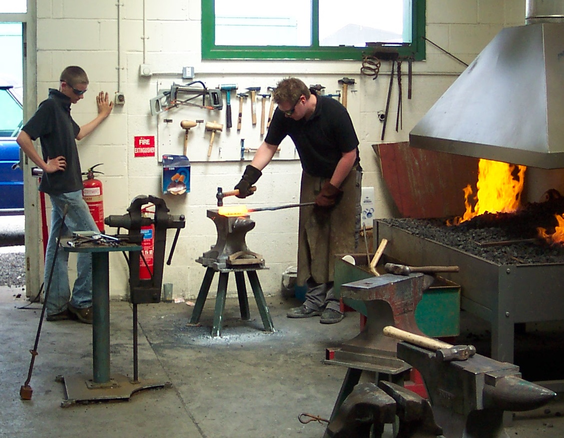
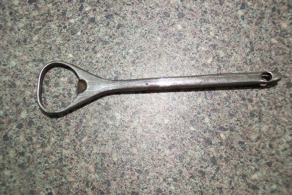
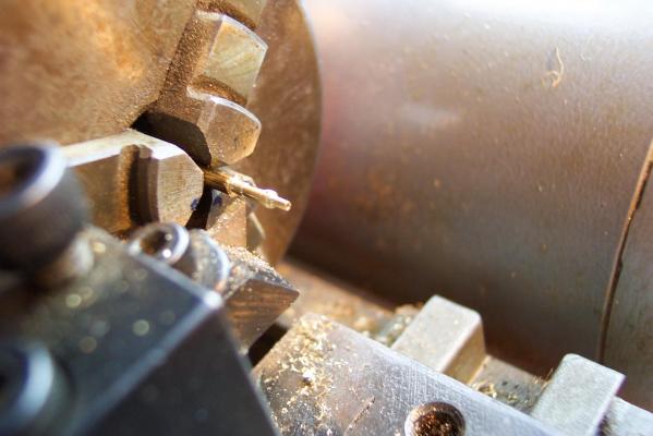
In the meantime I thought you might be interested in another valuable tool for modelers. Yes it is a bottle opener which was forged for me by my youngest son James. You may notice that it has a sort of wood grain effect. This because it is made from a latter day form of Damascus steel. If you were to try to cut it with a hacksaw you would mark the surface then the hacksaw blade would lose its teeth. I believe the original Damascus steel came from India and was used for the finest swords and gave the blades the beautiful patterns that showed as they were turned in sunlight. 18th century officers probably had swords with blades made with this type of steel which had the strength of tool steel and the flexibility of mild steel. Apparently its production ceased about the time this Unicorn was built and the knowledge on how to produce it was lost. Some blacksmiths around the world are trying to rediscover/reinvent the original method. In the meantime the latterday method is to take alternating pieces of tool steel and mild steel and fire weld them together. The resultant billet is then hammered thinner then folded over. The folded parts are fire welded together, hammered thin, folded and so on. This is done about 200 times - the more times the finer the "grain". The photo shows my son (complete with watcher) firewelding a billet of Damascus steel having just folded it over. My bottle opener was one of the items forged from this billet. As you probably guess, if I have any metal work queries, my son is the person from whom I seek advice.

-
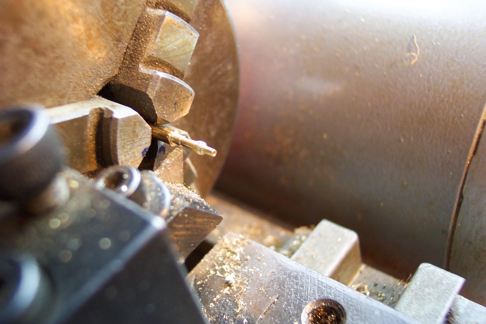
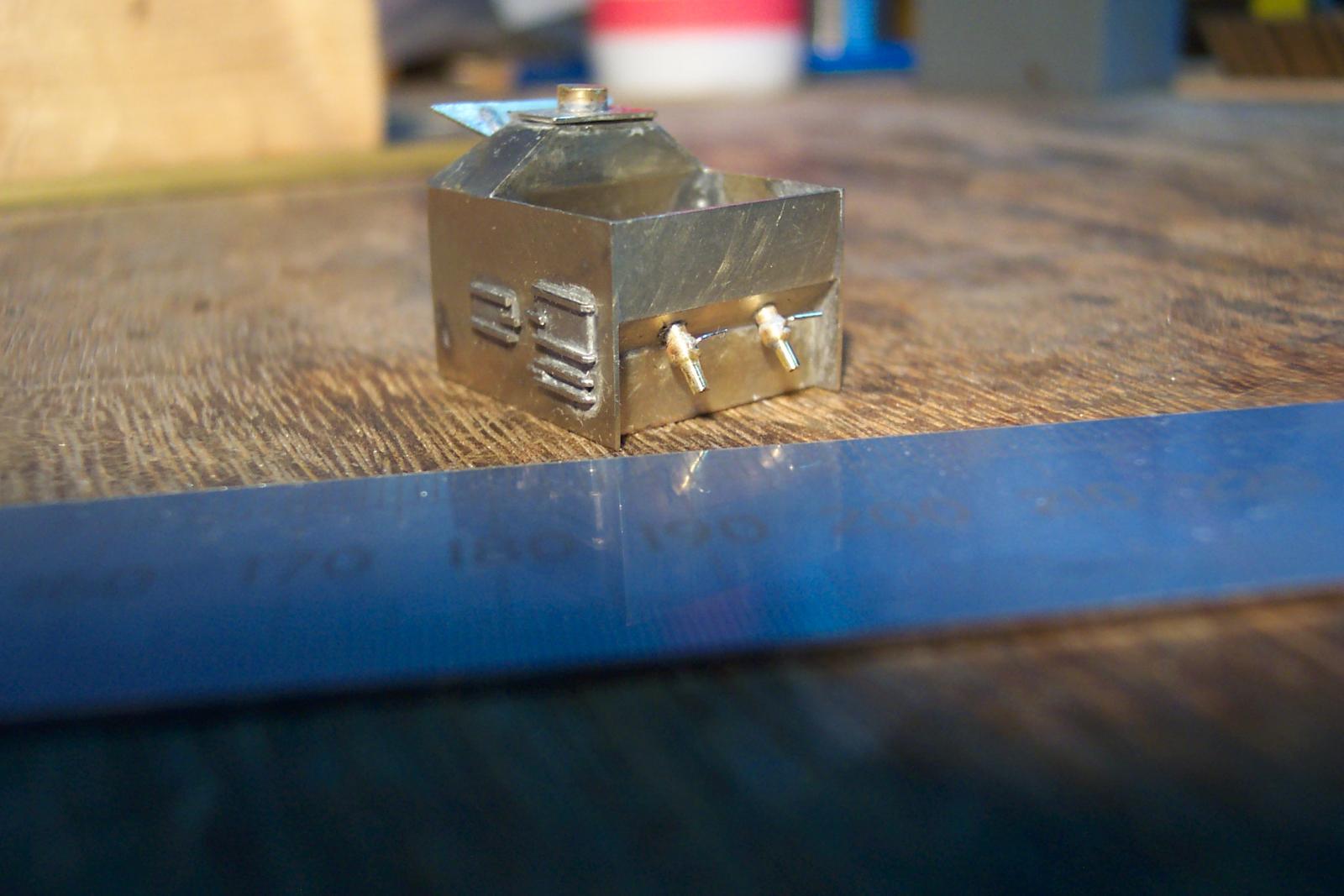
Moving to the rear of the stove I made up two new cocks. These were turned in the lathe: The turnings were cross drilled and fitted with 0.3mm wire handles. These cocks were then fitted to the stove. Next up are the stove legs. I have 1mm angle brass milled ready for this. I am experimenting with embossing them with cosmetic rivets to see if they are worthwhile.

-
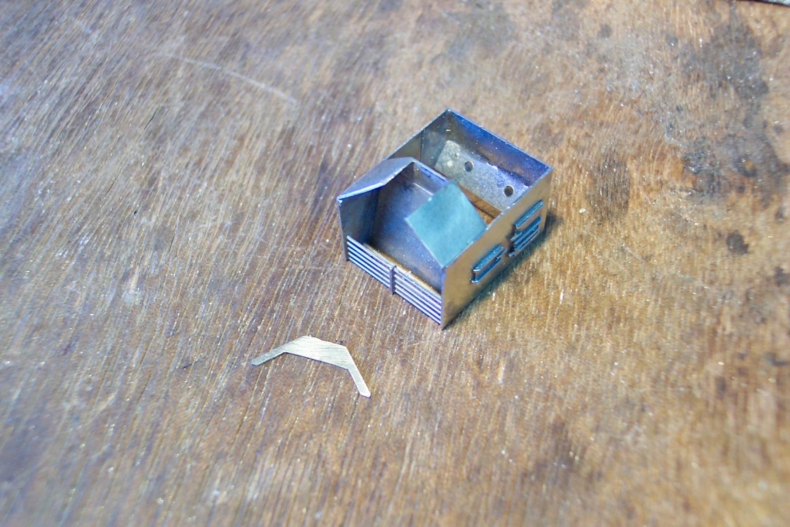
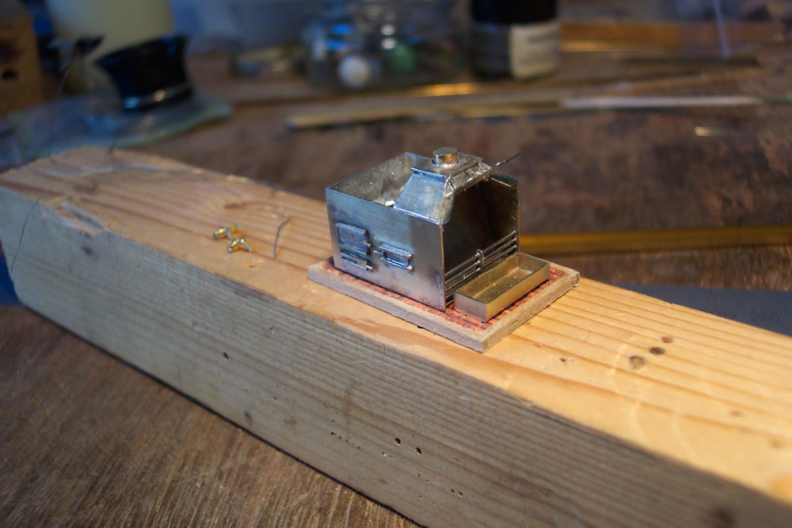
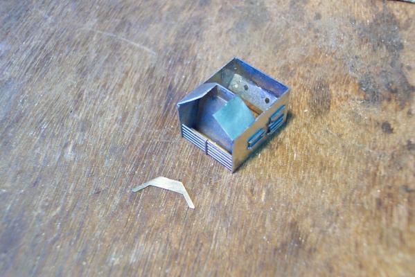
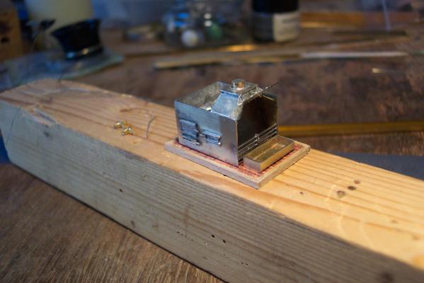
I was not happy with the hood front so I took it and the left side off. The next photo shows the replacement side in place. I cut it the right height, plus the rear edge was cut to the correct size, but the front was left over long for now. This was fitted. The replacement hood front is lying in front of the stove. I actually had difficulty fitting the new front so I produced a new one with a large tab on the top. When soldering it in place I gripped it using locking tweezers on the tab which allowed the part to be pulled in to position. The tab and the excess on the left side was filed off. To finish the hood body I added a plate on top which has a slight overhang to represent the flange between the hood and the flue (to be constructed). When the stove is installed the main part of the stove will be go in through the waist area. The flue will have to be installed separately down through the foredeck. To help align the flue I have fitted a small length of brass rod on top of the hood. I also decided to model the hood in the open position. The hinges were short lengths of 1mm x 0.7mm strip. They were soldered to the lid part first, bent to shape then the whole unit was soldered to the hood front. The various plans and pictures show the lid either being held up by a latch or a length of small link chain. A reasonable representation of small link chain can be made using two pieces of fine wire twisted together. The more it is twisted the smaller is the simulated link size. I used some core wires from instrument wire. I took a length bent it in two then trapped the cut ends in the vice. I put a small drill bit through the loop end. Then using the bit as a wrench carefully twisted the wire. This makes the two wires wrap around each other. If you grab the end with pliers and twist, one part of the wire tends to remain straight whilst the other wraps around it. This latter approach does not give the desired effect. In hind sight, soldering these hood parts together would have been easier if I had left the fire grills off until after this point. This would have allowed it all to be soldered from underneath.
-
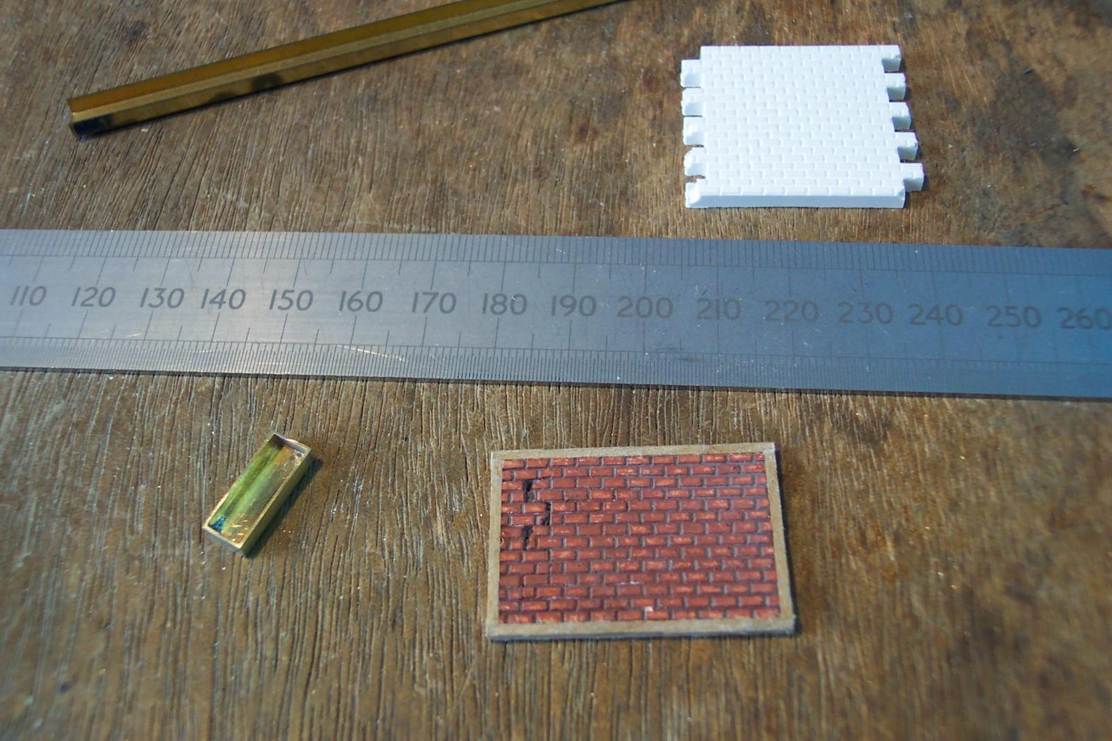
Some progress on the Brodie stove. Photo 1 shows the completed base. The brick pattern was produced using an old "Linka" set. The set consists of rubber molds and a powder similar to plaster of Paris. Top right in the picture is a white block of brick produced in a mold. I needed two of these to make the base. Where they joined left some small holes which will be covered by the drip tray when everything is finished. I painted the brick block over all dark grey. When this was dry I dry brushed the bricks with red bauxite colour. If this is done carefully it leaves the "mortar" between the bricks a grey colour. The base was completed with a walnut surround attached with PVA glue. A quicky was the drip tray which appears in the bottom left of the picture. I was feeling lazy so I used a piece of brass channel (top left). This was the right width but slightly too deep. The ends were over size pieces of 0.4mm brass. I soldered these on the ends then filed them down to size. Finally I filed the whole tray down to the correct height. The down side of using channel is that it has rounded edges - some careful filing can disguise this. Photo 1

-
Ed, The model on the finished base looks absolutely beautiful. I also love your workshop. Still, as they say, a workshop and tools are only as good as the person using them. I await with great anticipation your next project.
-
What do you use your mill for ?
ianmajor replied to captainbob's topic in Modeling tools and Workshop Equipment
Meredith, Mark has covered all the basic tools to get with milling machines. One fairly cheap item that I would add is an Eclipse pin chuck. I have included a couple of pictures to show what I mean. The first photo shows my EMCO micromill with a collet holder in the top of the picture. The collet set I have which go in to this holder can hold drill bits, mill bits etc from 1mm diameter up to 10 mm. To hold anything of a smaller diameter than 1mm, I fit the Eclipse pin chuck in to one of the 6mm collets then the small bit is clamped in the pin chuck. The pin chuck is in place just below the top of the photo. Also in the photo are a couple of clamps to hold the work and a machine vice. The second photo shows the components of the collet and pin chuck set. On the left are the two parts that make the collet holder, then comes the set of 10 collets. On the right is the Eclipse pin chuck with one of its (micro 4 jaw) collets fitted along with two other micro collets for different bit sizes. Notice - this type of pin chuck has a cylindrical tail that allows it to be gripped in larger chucks or collets. Not only do I use this pin chuck in this way but also as a hand drill or to hold small components when I work on them.

-
Intro to Card Models Part VI: Building V108 - The Superstructure
ianmajor replied to ccoyle's topic in Card and Paper Models
Chris, It looks like the vote is going towards the detail - no surprise there. I am interested to see how (and with what) you tackle the window glazing. -
One reason that appeared in a previous thread for not glueing masts in place is that they are easier to repair/replace in the event that they are damaged.
-
Piet, At first glance I thought the first photo was of the inside of a railway carriage. It gives an idea of how cramped the accommodation was.
-
Hamilton, Nice work. Like Mike I am taking a lot of inspiration away from this build for my own efforts. I will have to stand over you with the "cat" because I want to see more, More,MORE...... :)
-
Jan, Lovely work. You are a good ambassador for modeling in card.
-
Hum - frustrating. Never mind, better luck next time.
-
Mike, Thanks for the info. The Guadeloupe was one of the ships that I looked at. My proposed layout of the waist, if observed from above, fits in with the Guadeloupe layout. The 'temporary' parts of the gangways should only be two planks wide. Mine will be slighter wider to mask the bulkhead extensions. There should be a step up from the temporary to the fixed part of the gangway and again a further step up to the quarter deck. I won't be able to achieve that without rebuilding a great chunk of the hull - but starting from the beginning would be a different proposition. Your research, I feel, confirms my view that Coral have mixed an early hull with a much later superstructure.
-
Intro to Card Models. Pt. II: Start for FREE!
ianmajor replied to ccoyle's topic in Card and Paper Models
Thanks Chris. -
Piet, Great progress. I love the view along the hull, particularly from ahead of the bows. Very dramatic....... .....and thanks again for the background information on the prototype. It is absolutely fascinating,
-
What do you use your mill for ?
ianmajor replied to captainbob's topic in Modeling tools and Workshop Equipment
John, Useful stuff. Thanks. Bob, Also if you browse around Dan Vadas' logs you will see plenty of excellent examples of mill work. The latest one is on page 39 of his HMS Vulture build (see http://modelshipworld.com/index.php?/topic/230-hms-vulture-by-dan-vadas-1776-148-scale-16-gun-swan-class-sloop-from-tffm-plans/page-39 ) In it he mills the sides for a cannon carriage (a nice job for beginners). For milling the semicircular holes in the bottom of the carriage sides he uses ......... a ground down 10mm drill bit! There are many other members who demonstrate mill work in their logs but you may as well start at the top (crawl, crawl :) ) -
Lost for words other than stunning.
-
What do you use your mill for ?
ianmajor replied to captainbob's topic in Modeling tools and Workshop Equipment
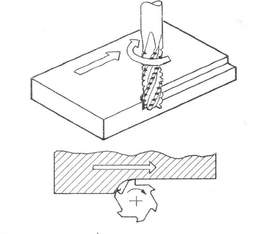
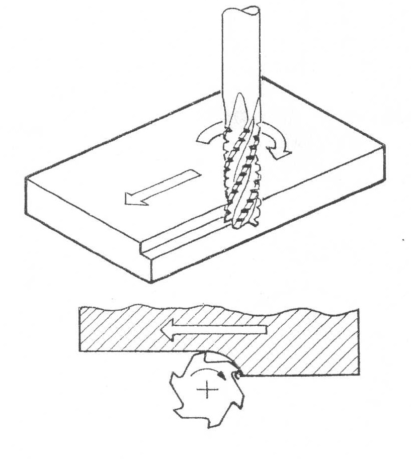
Tom, Gaeton is absolutely right. Milling bits are more complex than drill bits. There are different designs for different functions. They should be used wherever possible. However, I have successfully used ground down broken drill bits to mill very small slots. I have cut slots in brass and wood this way. With the brass I chain drill the slit then use the broken bit (same size) to mill the holes in to a slot. (Purists will be rolling their eyes now! ) The trick was to keep the length of unsupported bit as short as possible and to take it very, very slowly, taking very small cuts on each pass. For wood I keep the speed low to avoid burning. When milling you should always use a collet to ensure the mill bit is running concentrically. Initially I used an ordinary power drill type three jaw chuck and broke a couple of milling bits (expensive). Since using collets (sadly also expensive) I have not had any bit problems. Another thing to avoid with micro milling machines is "Climb milling". The small machines are less rigid than their larger brothers, so if you try climb milling (particularly on metal) the milling bit can grab (rather than cut) the work resulting in, at best, a mangled work piece or possibly a broken mill bit or even damage to the machine itself. Before I had the miller I did my milling on a micro lathe using a vertical slide. I had spent some time milling a piece and was approaching the end - got sloppy - and did my final pass using climb milling. It grabbed. It broke one cutting edge off the bit, left my beautiful work looking look at had been attacked with a cold chisel. The lurching machine also frightened the life out of me. Below are two diagrams that show the difference between conventional (first diagram) and climb milling. Conventional milling. Climb milling With regard to training - personally I have had none (which is probably obvious to those who have been formally trained) but am a cheerful amateur. There are plenty of small, cheap soft cover books available that give introductions to milling. On You Tube there are loads of "how to" clips on the subject (I recently looked at a series by Tubal Cain on making a single cylinder steam engine from basic materials). If you decide to get a milling machine then: Step 1 - read, understand and observe the safety instructions. Step 2 - read the basic operating instructions supplied with the machine. Step 3 - clamp a block of pine wood on the machine and fit a milling bit and try things out - as long as you have done step 1 and 2 carefully, and don't wind the bit in to the miller's table you won't do any harm. Step 4 - enjoy the experience. I find it a very satisfying experience to watch the miller in action (what a sad existence this man must live - I hear you say!).