.jpg.f4fa790b1fa2f0e00e3d149ed7bdd37c.jpg)

shipaholic
-
Posts
540 -
Joined
-
Last visited
Content Type
Profiles
Forums
Gallery
Events
Everything posted by shipaholic
-

Novel Way of Making a Stay Mouse
shipaholic replied to shipaholic's topic in Masting, rigging and sails
Thanks Druxey, yes it's 1:51 scale -
Thanks Dave, yes the stay is 1.58mm diam. perfect
-
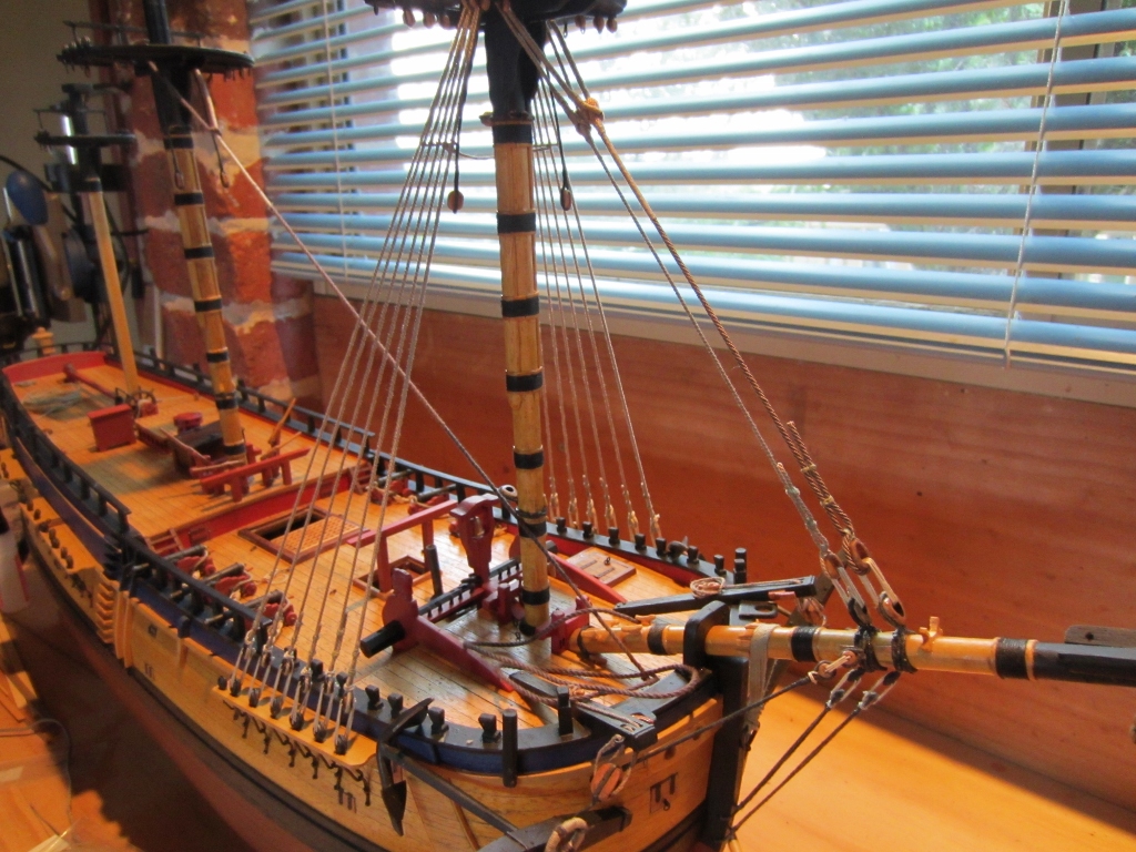
Yesterday I received the new rope I ordered from Chuck and its the right size for my stay. I spent the afternoon making the fore stay. I have put the details in a new post in the masting and rigging section for those interested in how I did the mouse. I am happy with the result and using the correct size rope means it doesn't look too bulky at the mast head. Cheers Steve
-
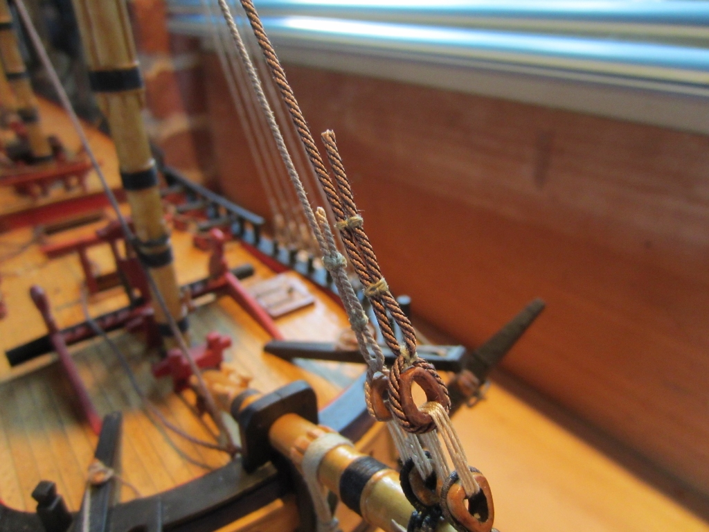
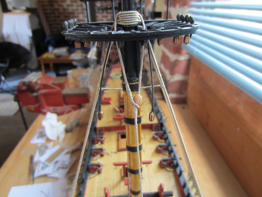
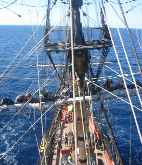
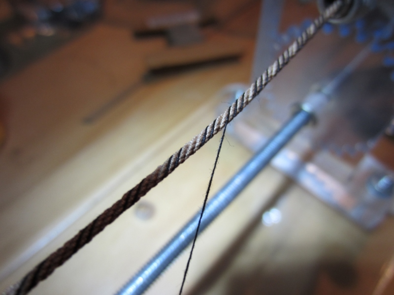
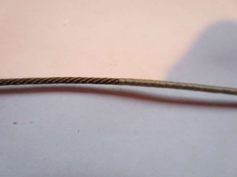
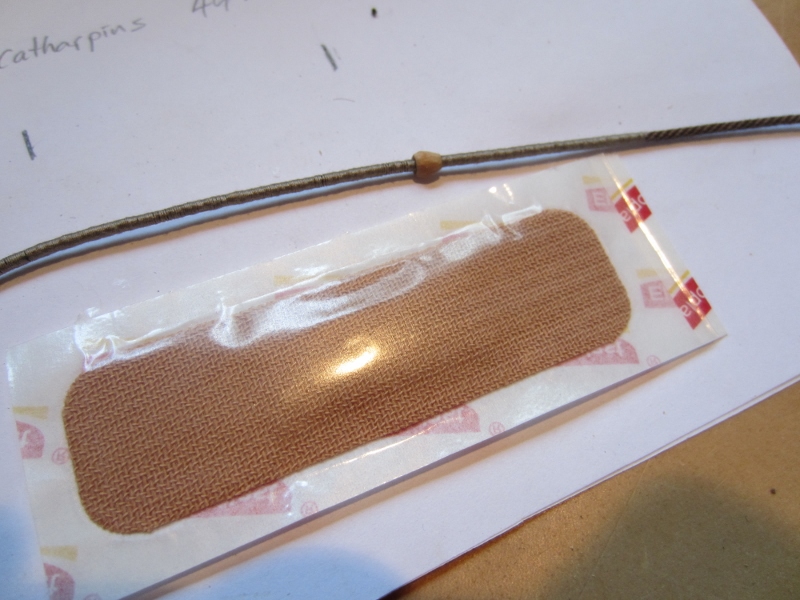
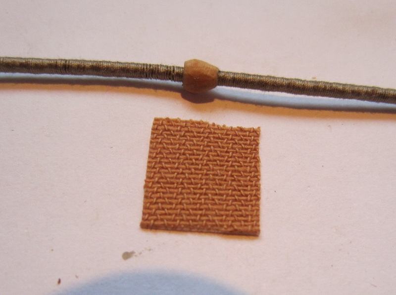
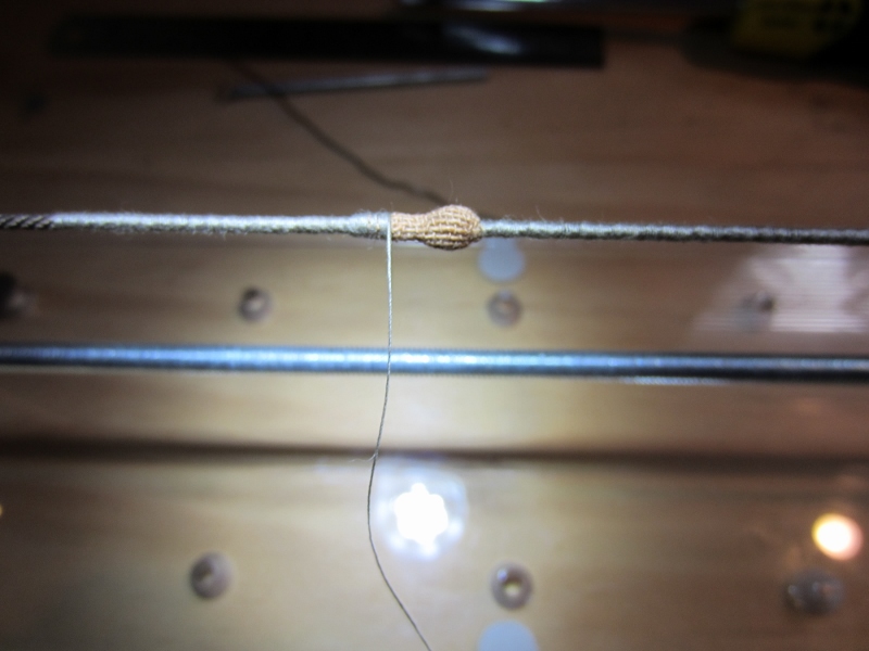
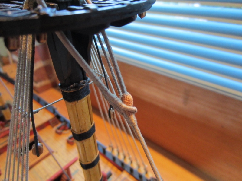
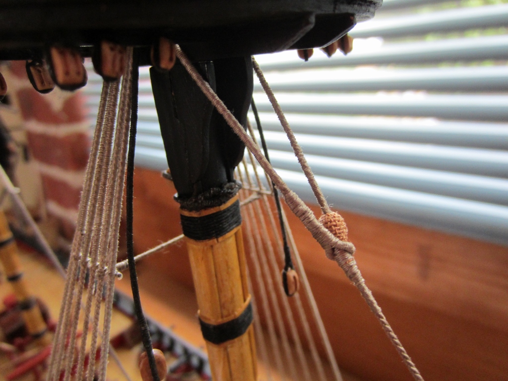
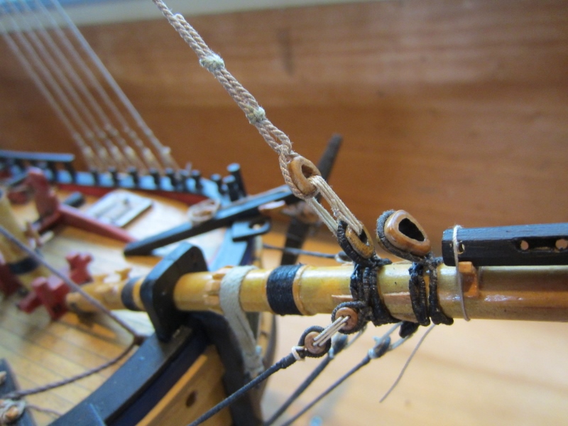
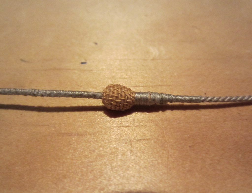
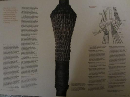
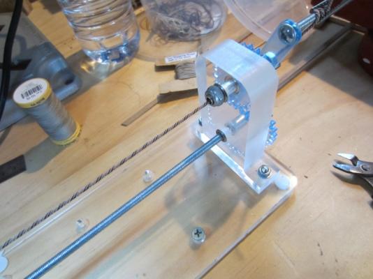
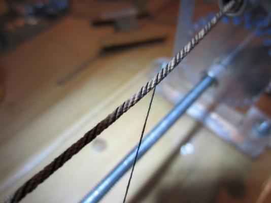
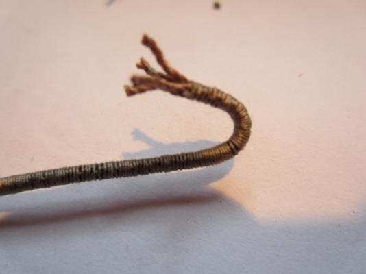
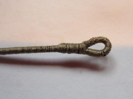
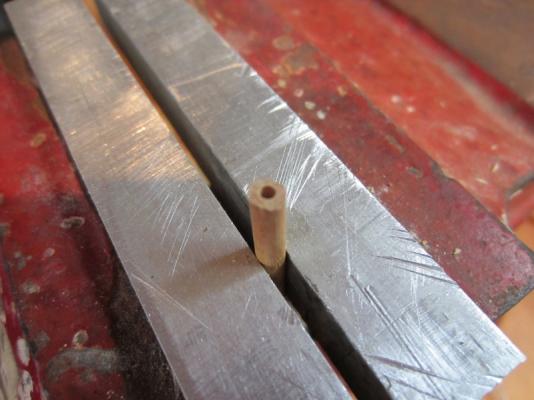
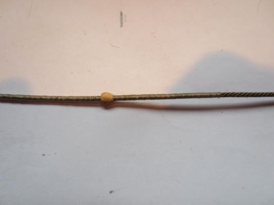
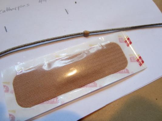
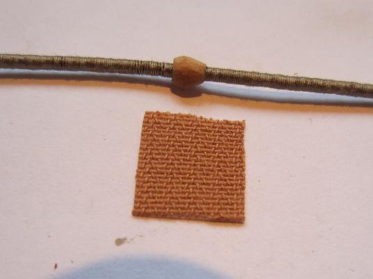
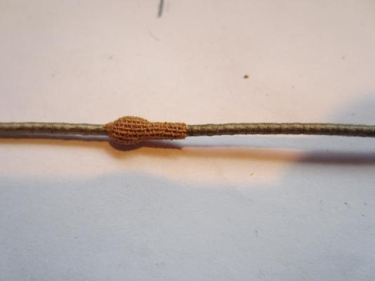
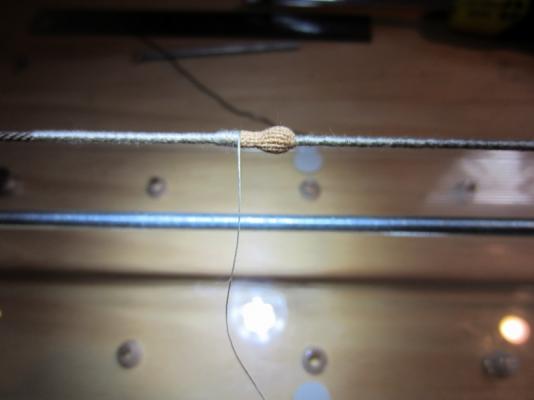
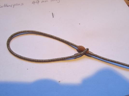
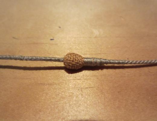
Hi everyone I stumbled apon this when trying to think of a way to make the mouse on the mast stays look realistic without having to weave the cover to get that knittled look. Here is a photo of the actual mouse for the Endeavour replica vessel I am using rope from Syren Model Ship Co for the stay, it is cable laid four strand rope. First I worm the rope on my Domanoff serving machine. I'm using black cotton so its easy to distinguish during the worming process, (the stays will be painted black later to simulate the tar) The rope is then served just beyond where the mouse will be The eye is formed by unpicking the ends of the rope, gluing them down to simulate a splice Then it is served over the splice The mouse is made by drilling a hole in a piece of dowel. The dowel is sanded to a cone shape on the end then cut off and sanded to shape and slipped onto the rope. The create the woven effect over the mouse I am using a flexible cloth wound dressing, its self adhesive so very easy to attach. The lower part is served. A little bit of PVA glue on the join will stop the self adhesive letting go in the future. The completed stay


- 11 replies
-
- 38
-

-

-
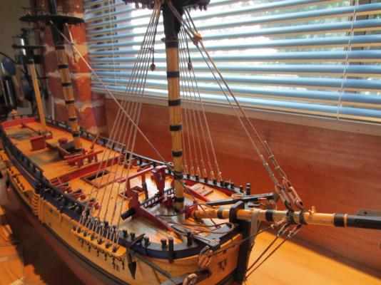
Harvey Wow, just discovered your build log. I built the Corel Victory a long time ago with a lot of mods to make it look more realistic. But you have done a fantastic job using the parts supplied, absolutely brilliant, well done Steve
-
Hi Dave Thanks for the info. Yes similar, I am basing the rope size on 7" rope for preventer and 10" forestay My Endeavour is 1:51 scale so the preventer should be: 7" circumference x 25.4 = 177.8mm divided by Pi (3.1416) = 56.6mm diam. divided by 51 = 1.11mm 10" circumference should be 1.58mm Cheers Steve
-
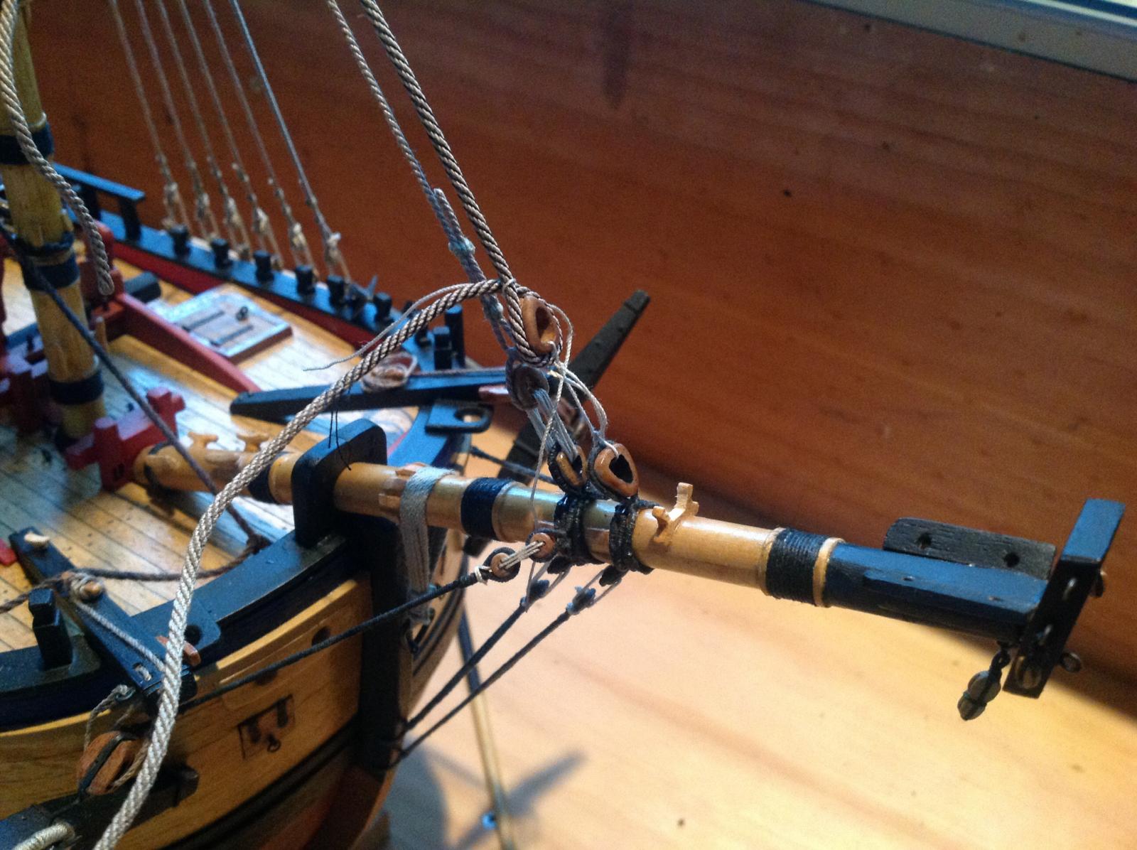
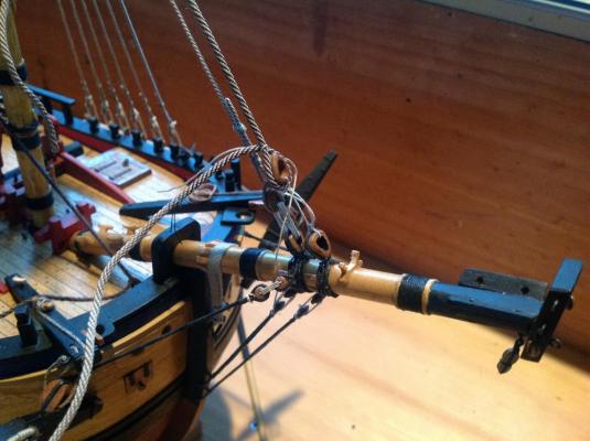
I started setting up the fore stay. I wormed the rope and temporarily rigged it in place to work out where the serving, mouse and eye will go. According to my sources a ship this size had a fore stay made of 10" rope, which equates to 1.58mm diameter at this scale. I am using 1.57 mm Syren rope, but when I measure it with a calliper its 1.90mm. It looks a little too thick. The preventer stay is okay, it's made from 1.14mm rope and when I measure it with the caliber it's about 1.1mm, so pretty right. I might have to order the next smaller size for the fore stay.
-
Hi Pat Yes I put a little bit of PVA on where the ends join and I will be painting it black so the paint will also help hold it permanently. No I wouldn't rely on the adhesive on the dressing to hold it forever. Steve
-
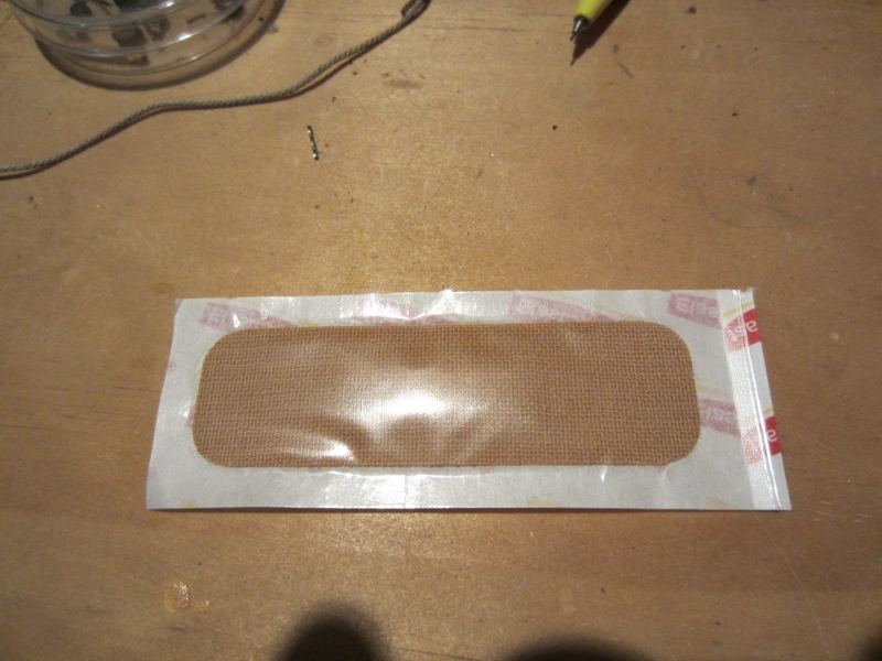
Thanks Mike Yeah it was one of those eureka moments. I was initially looking at gauze bandage in the supermarket then I saw the Elastoplast and thought yes that's it, texture was right, flexible to mould around the mouse and self adhesive so it would stay in place long enough until it's sealed permanently with glue or paint Cheers Steve
-
Hi Pat I used Elastoplast Heavy Fabric, there a few different ones available, depends on the texture you need for your scale. I got mine at Woolworths Cheers Steve
-
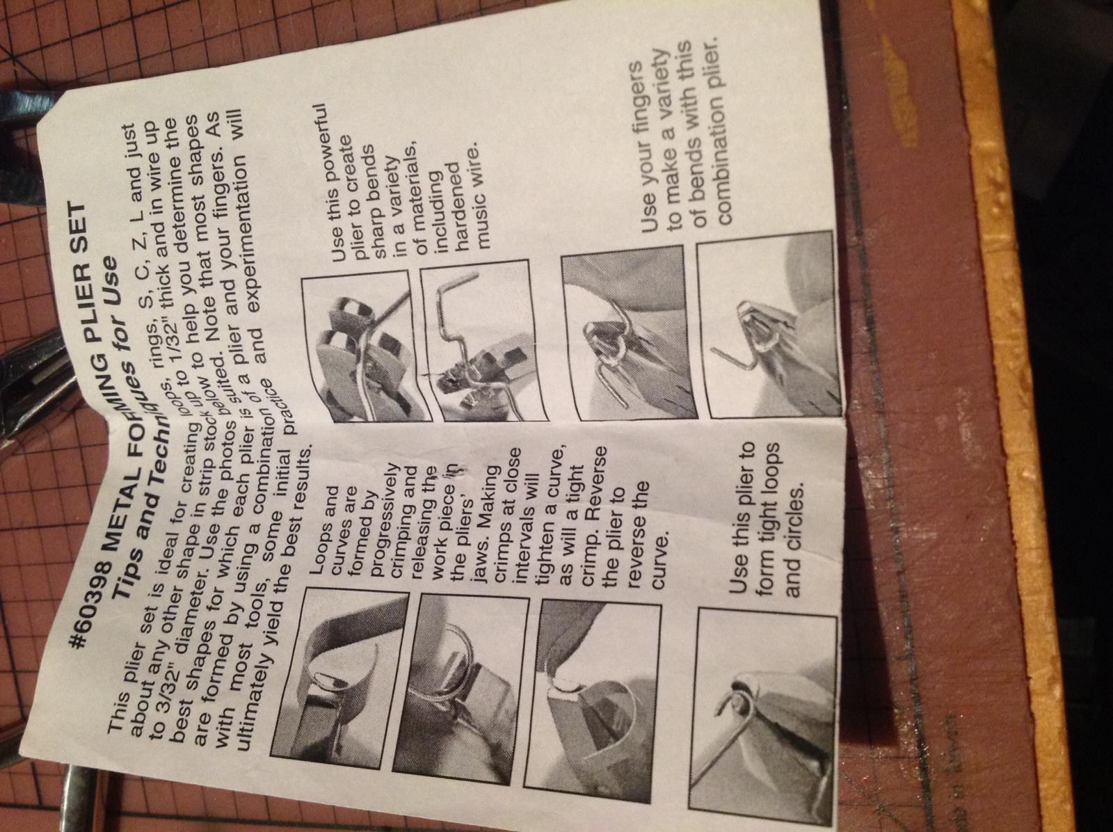
Slightly different Greg, Maybe Hobby Tools don't have them any more but yes Slog they are on the Micro Mark website

-
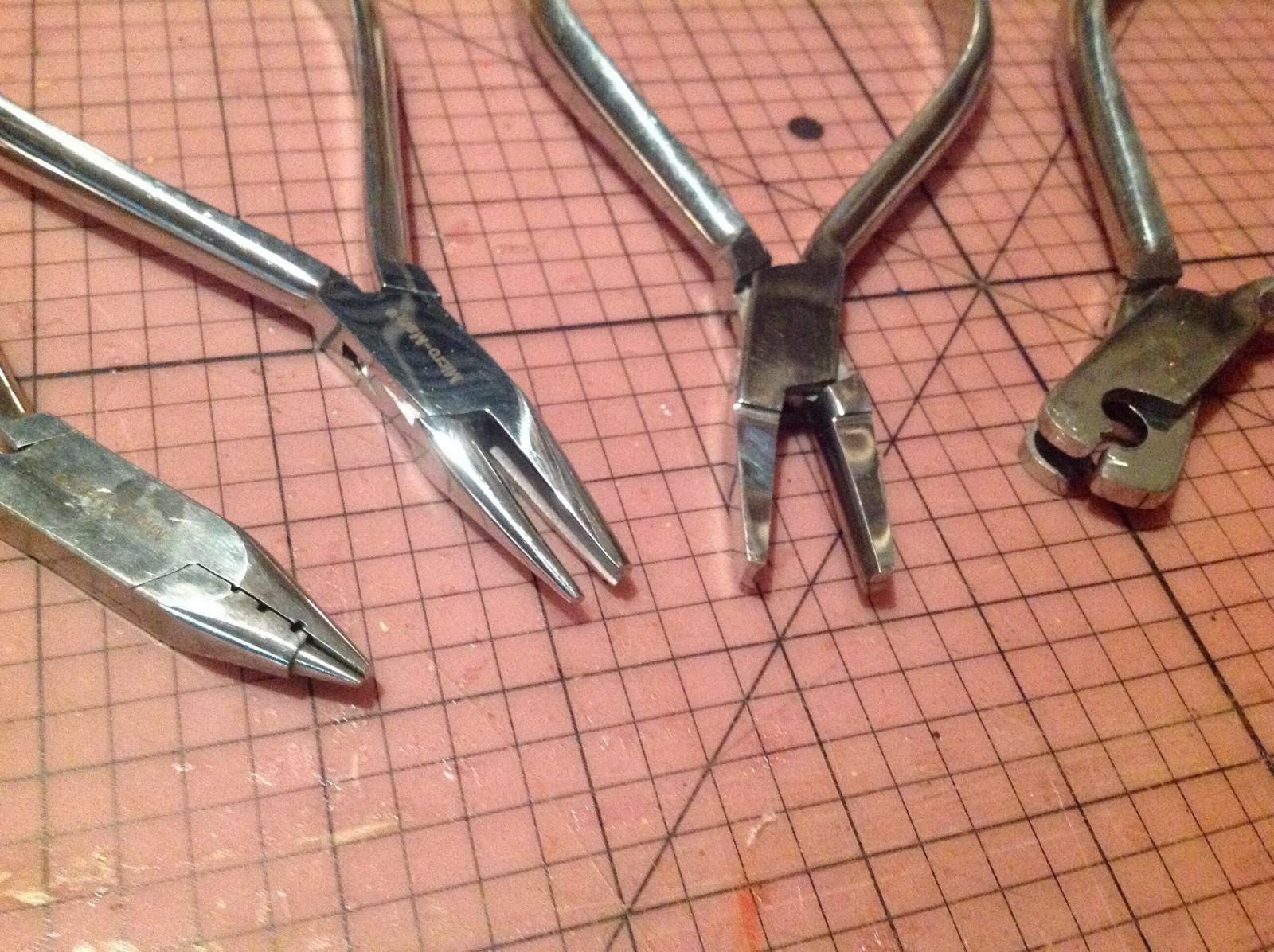
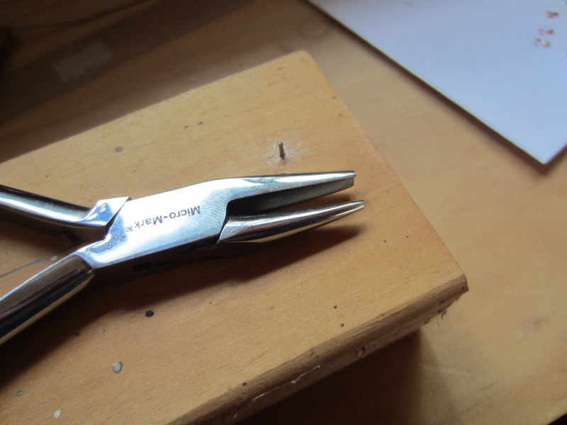
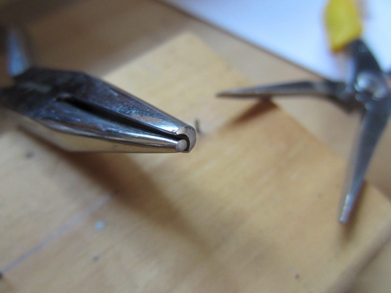
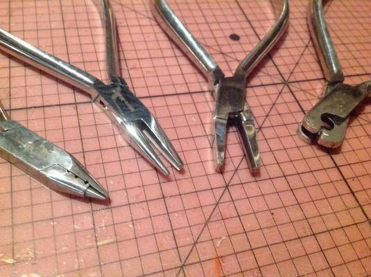
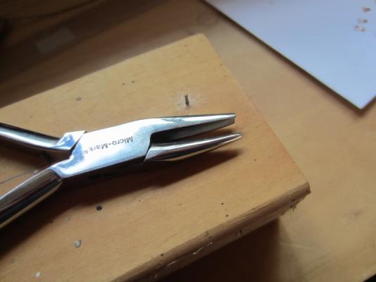
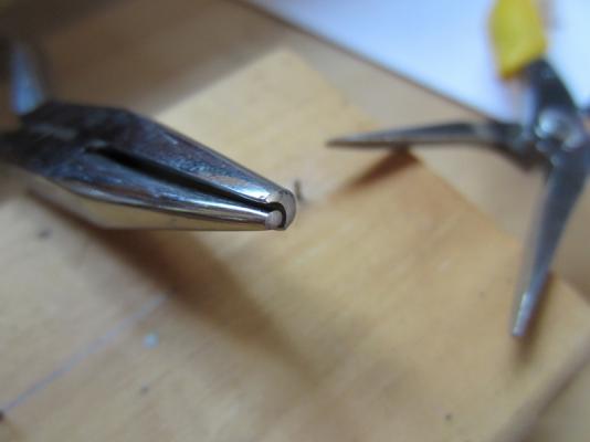
Thanks Slog Greg, I can't remember where I got those pliers they came in a set of four different ones, I think it was Hobby Tools Australia www.hobbytools.com.au I just had a look on their site but couldn't find the ones I have but they have lots of other good stuff
-
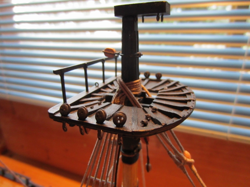
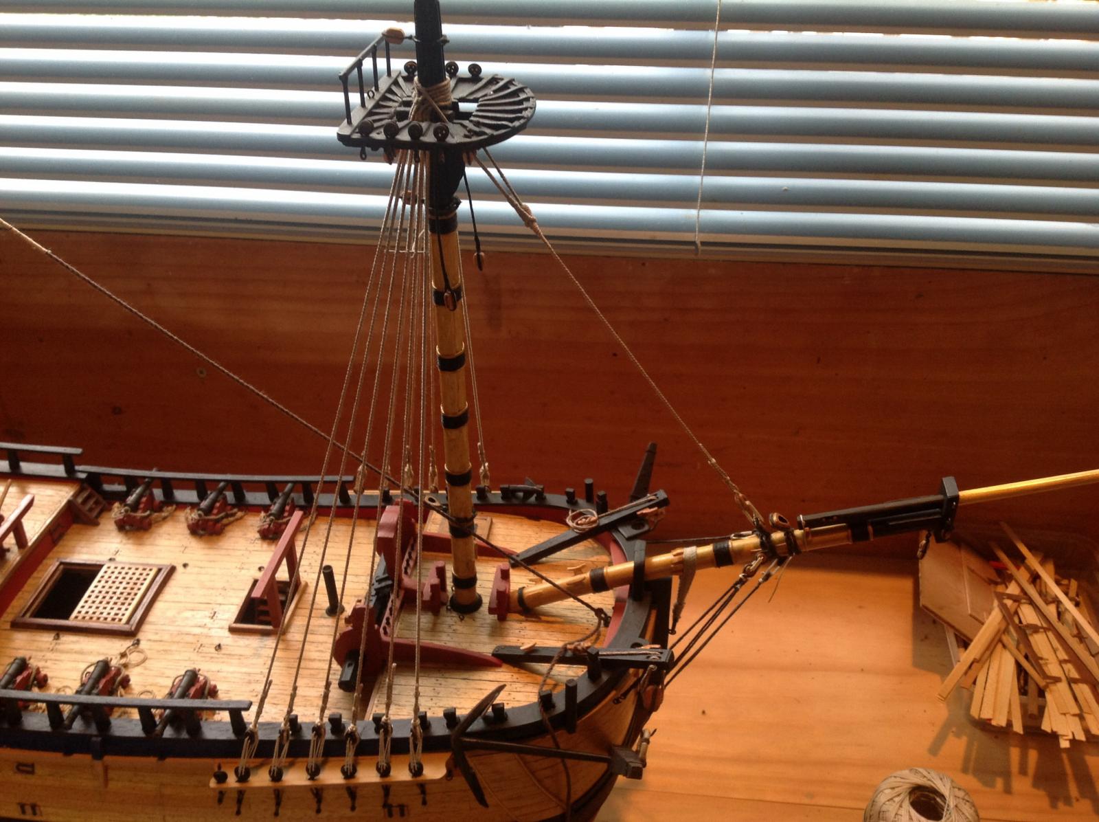
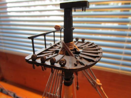
Hi Mike I had a look through all the reference books etc I have and couldn't find anything on crows feet. Theres photos of a 1:24 model of the endeavour in a NZ museum which show 14 holes in the top for the crows feet. I reckon your'e right, 18 might be too many, go with 14 or 15. Another error in AOTS I guess (there are lots, so I don't use it as the bible) I have 18 holes in my tops because I followed AOTS Keep up the good work Steve
-
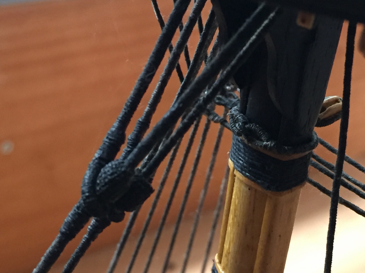
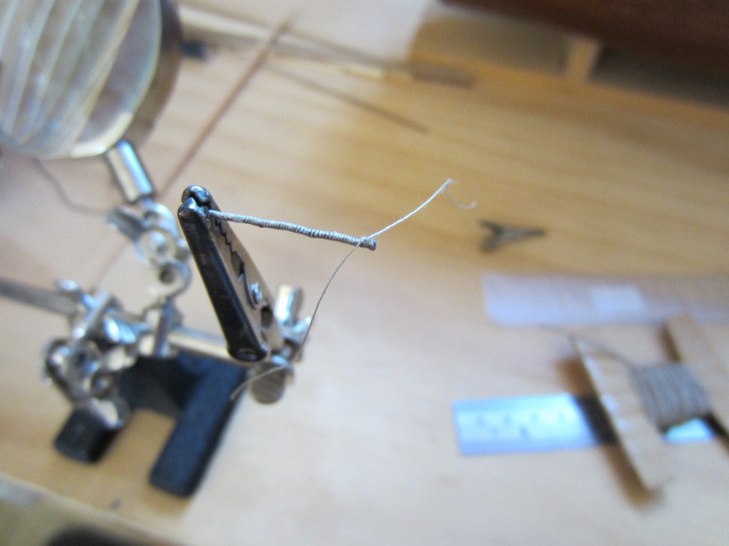
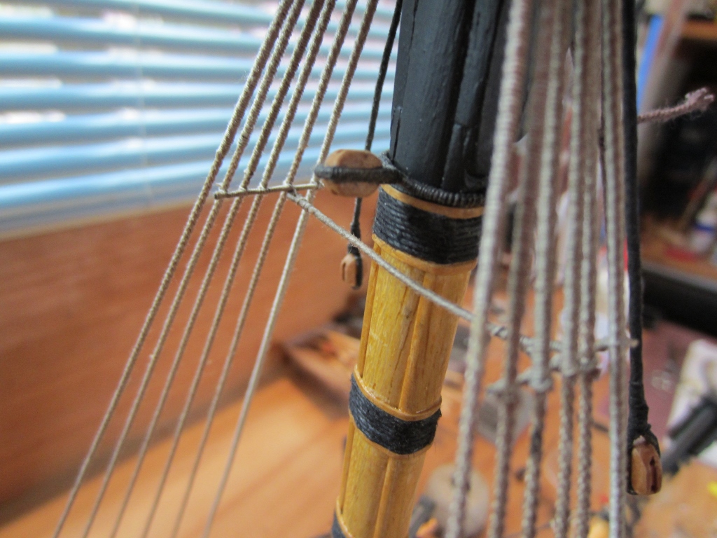
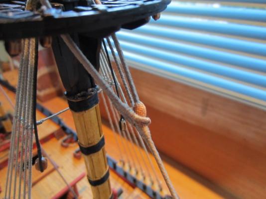
Some innovation I started making the lower stays and was thinking how I would make the mouse. I have seen other builders on this site weave the knittled cover using thread, and I thought, nup, not me. I came up with a better idea - can I use something that is already woven, like some sort of fabric? Then I thought what about wound dressing? I tried it and it worked brilliantly, its already adhesive and very flexible so it moulds around the mouse (made of wood). Once I blacken the stay with black paint and it will look pretty right I reckon. This one is the fore preventer stay which is smaller than the fore stay, the effect will probably be better on the bigger mouse of the fore stay. I knocked this one up pretty quick just to see how it would turn out so the serving is a bit rough. When I make the next one I will take some pics and create a separate post in the section on rigging. Cheers Steve

-
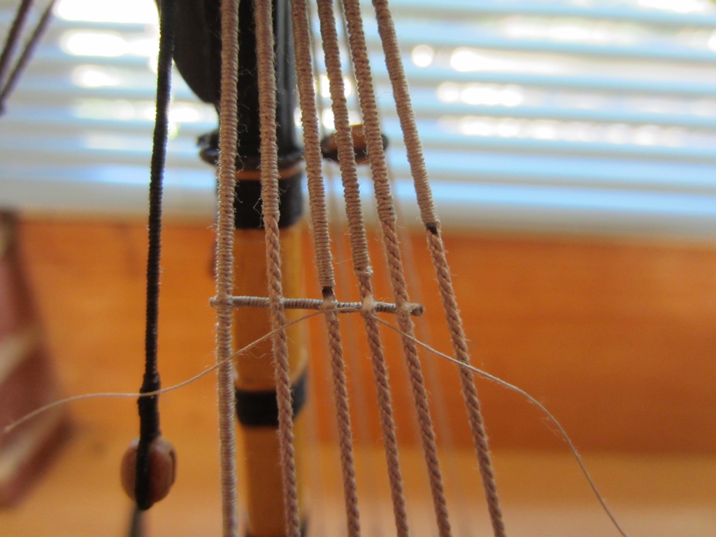
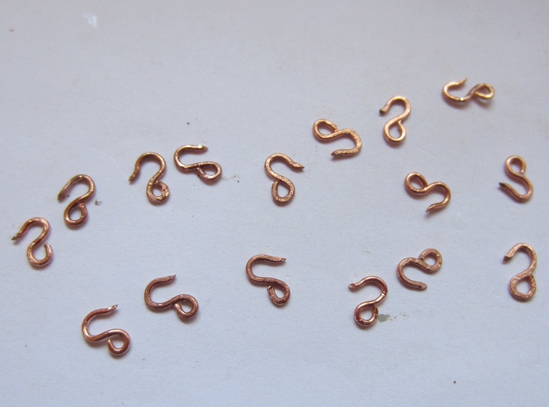
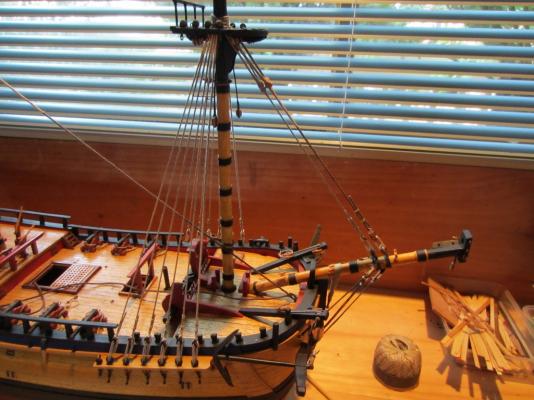
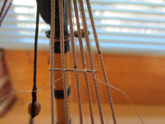
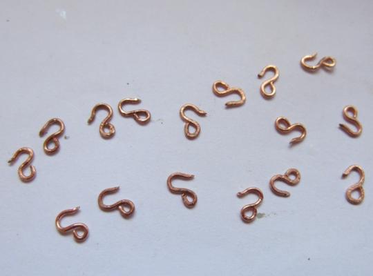
Hi Today I was busy making the futtock staves and catharpins on the foremast shrouds, I also made all the hooks for the futtock shrouds. These special pliers make the hook-making easier. The futtock staves are made of served thread, I thought they might be too flexible but they are fine. The futtock staves on real ships are served rope so i thought I would keep it authentic. The catharpins are also served, their length has to be perfect otherwise they pull the shrouds together or allow the shrouds to spread once the topmast shrouds are fitted. Cheers Steve


-
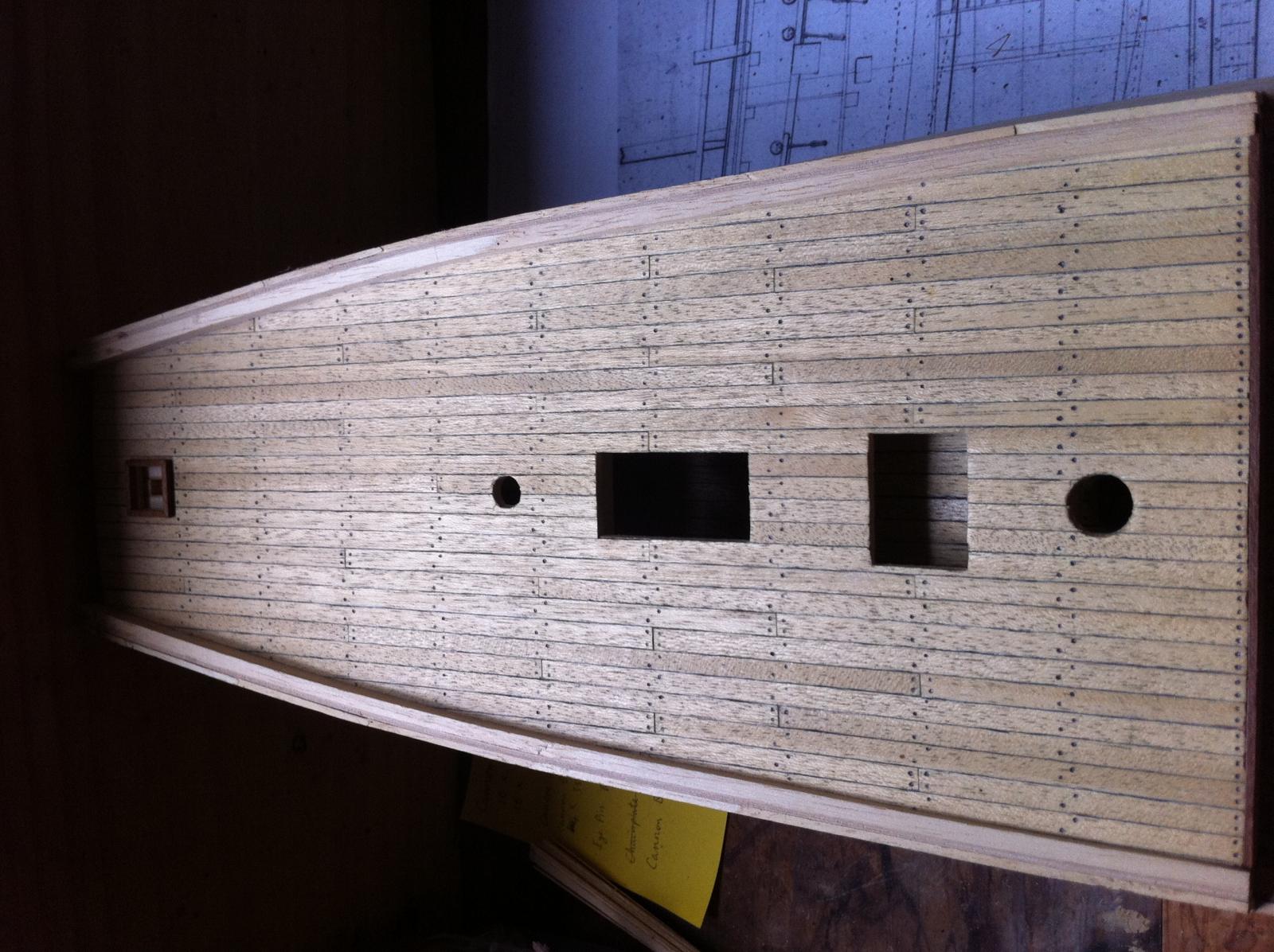
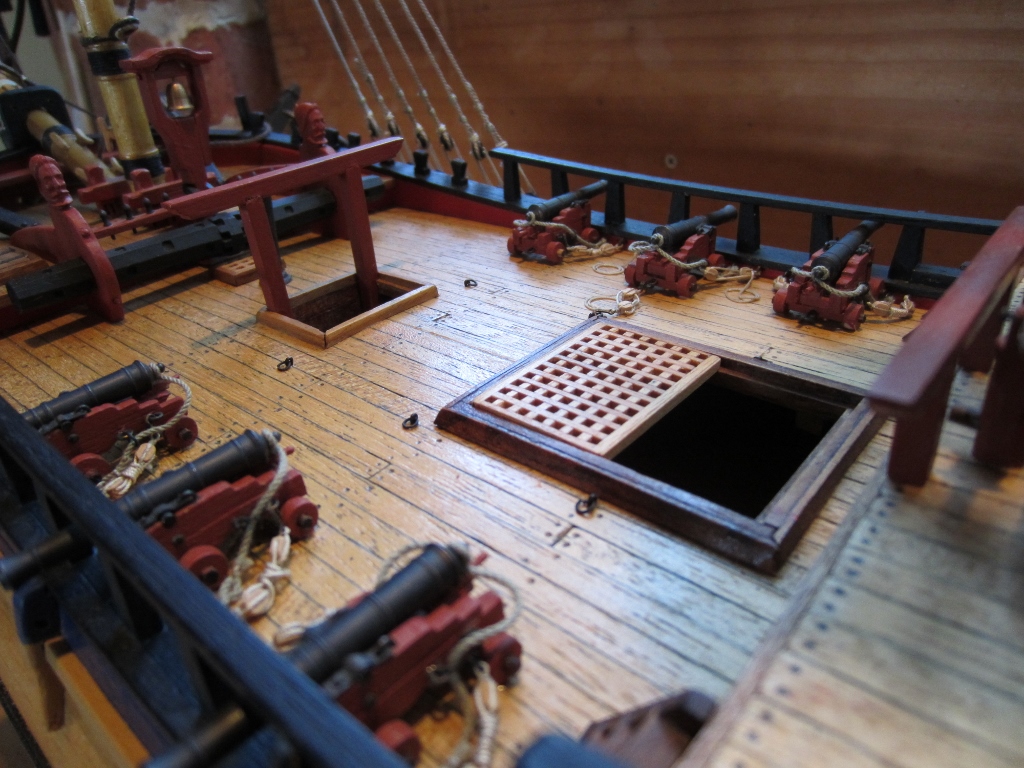
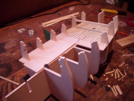
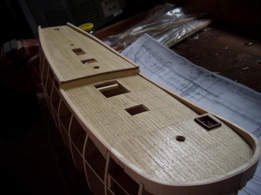
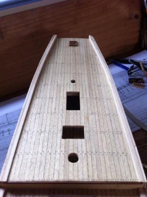
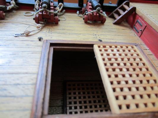
Hi VonHoldinghausen Thanks for the compliment. The decks are the planks provided with the kit, I blackened the edges with a soft pencil to simulate caulking and the nail holes are drawn on with a pencil. No special coating just two coats of sanding sealer. I don't have many pics of the actual laying of the deck Cheers Steve

-
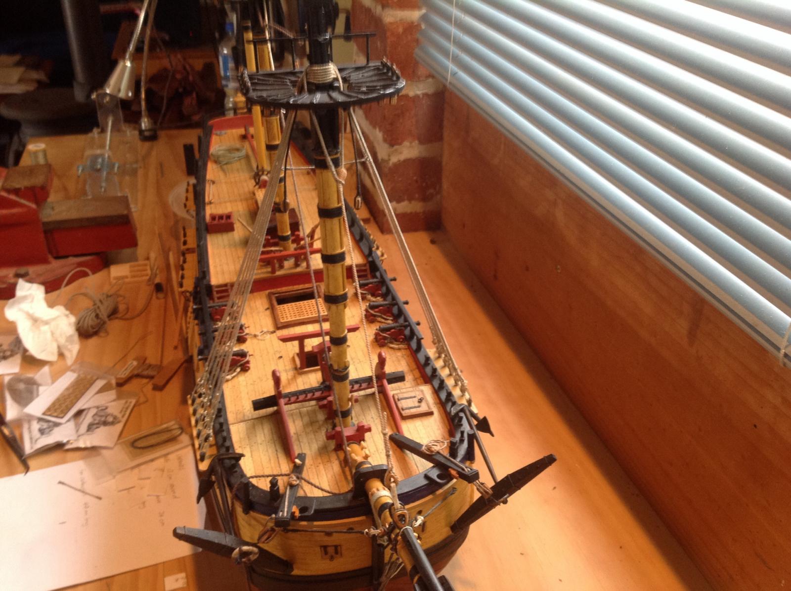
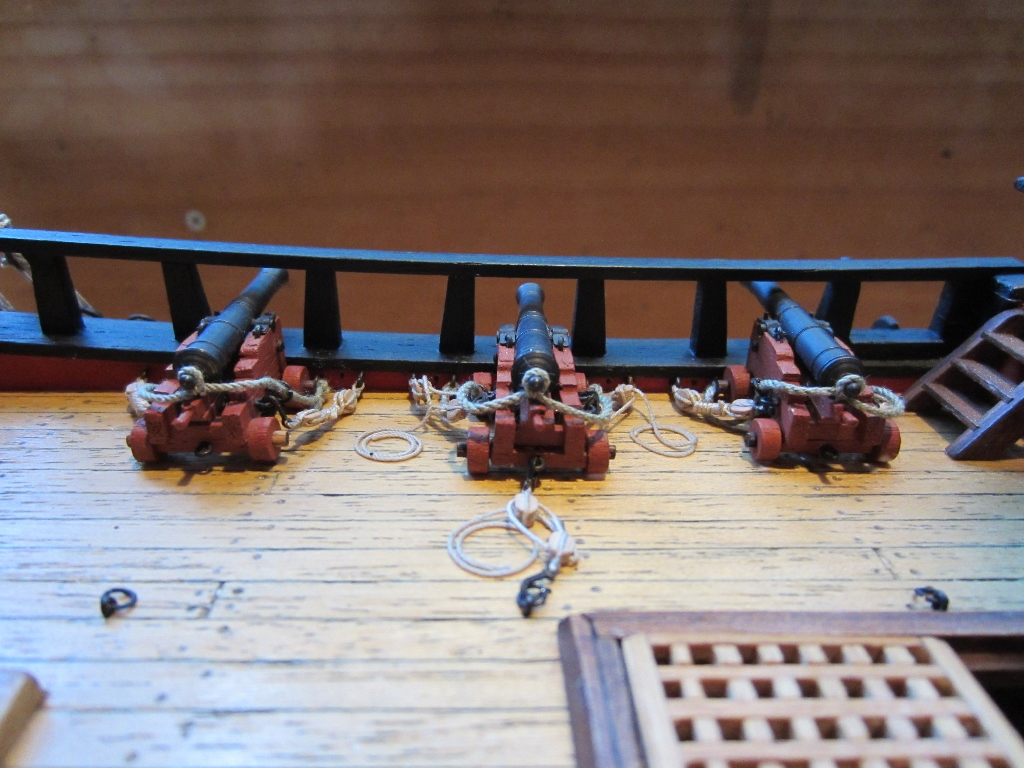
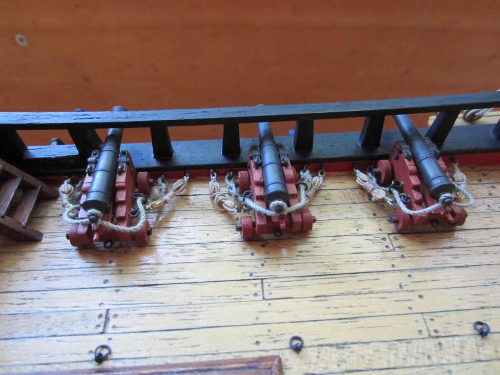
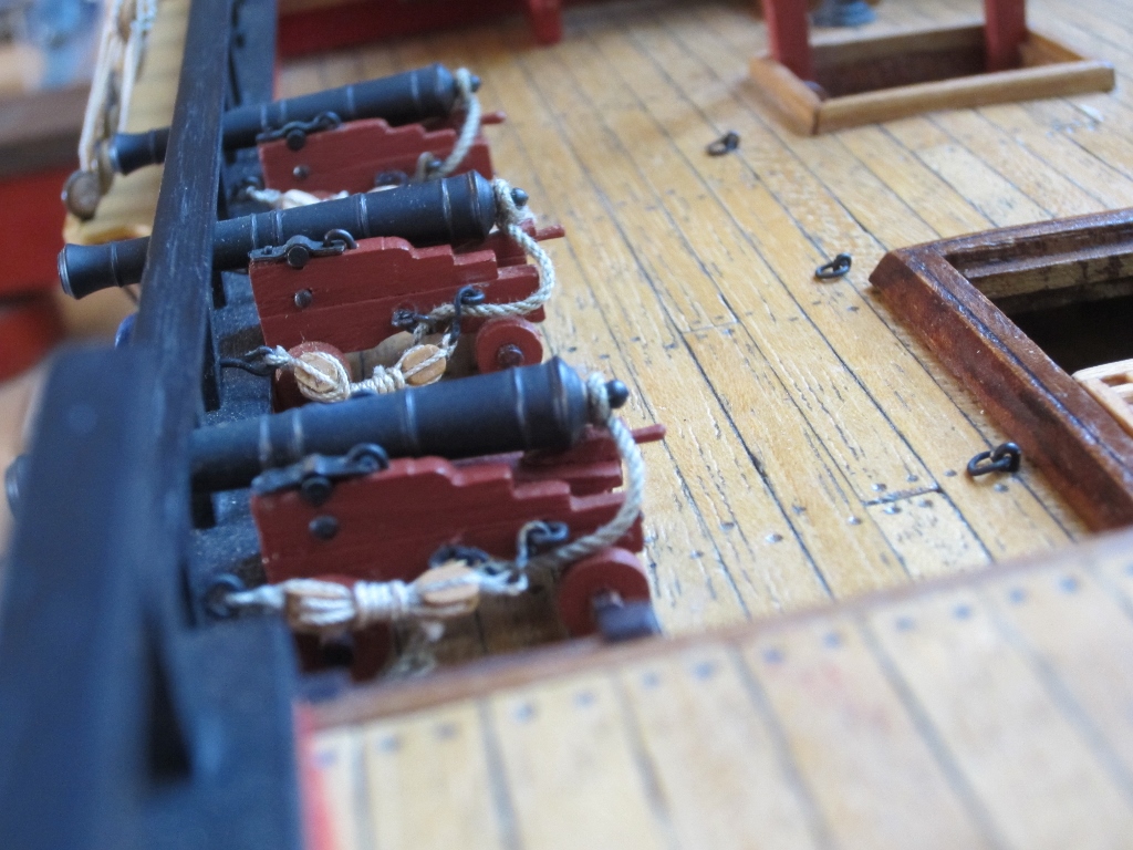
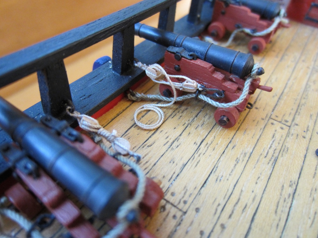
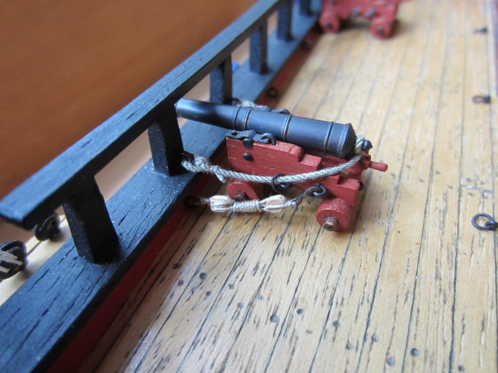
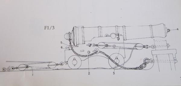
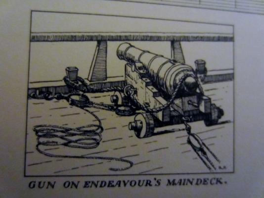
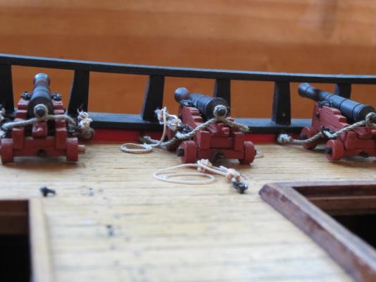
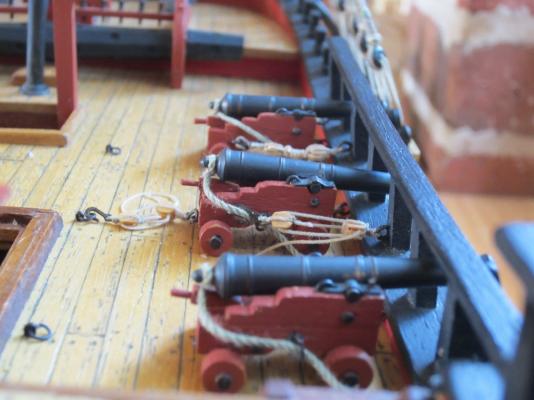
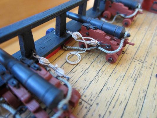
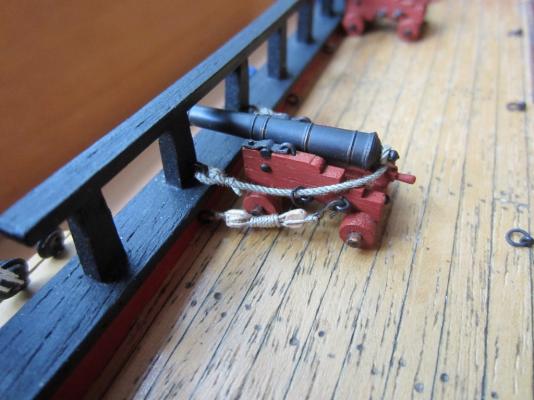
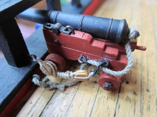
The question I raised with myself a few days ago about what might be the correct method of rigging the gun tackles has been bugging me. The diagram from Ray Parkin's book convinced me that the diagram I followed from the AOTS is wrong. Endeavour's guns did not have that third, higher, eyebolt on each side that are shown on the AOTS diagram so rigging the tackles to the rail posts doesn't work when the tackes are hooked to the lower eyebolt. The tackles would foul with the recoil ropes when the gun is fired. So I re-rigged all of the guns today to what I think is the correct configuration. Guns are finally finished, now I can go back to rigging the shrouds. Cheers

-
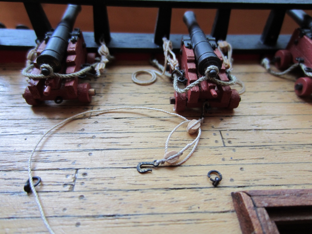
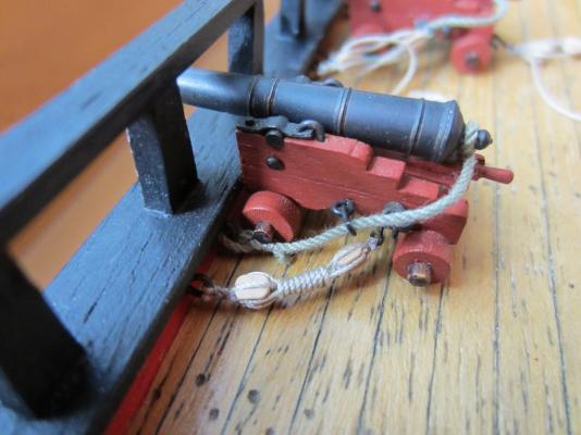
More work on the cannon. I am setting up just one of the guns with tackles appearing ready to use instead of the rope expended by wrapping around the rope between the blocks and also with the train tackle fitted


-
Today I was fitting the tackles and recoil ropes to the final two cannon (I kept putting it off because its so fiddly) and I had a thought about how the tackle and recoil rope should be rigged. I think it makes more sense to have the recoil rope above the tackle rope. I have already rigged all the other guns with the recoil rope under the tackle. If anyone has info on which is the correct configuration I would be grateful. Cheers Steve
-
Robin Yes I agree, the Endeavour might have had two binnacles, a small one either side of the skylight.