HOLIDAY DONATION DRIVE - SUPPORT MSW - DO YOUR PART TO KEEP THIS GREAT FORUM GOING! (Only 13 donations so far - C'mon guys!)
×

alross2
-
Posts
408 -
Joined
-
Last visited
Content Type
Profiles
Forums
Gallery
Events
Everything posted by alross2
-
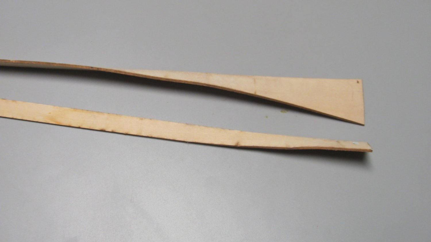
 Did a little experimenting. Photoetch is becoming increasingly expensive, so I'm seeking alternatives for items which do not require the strength of metal. Previously, small detail items that weren't feasible to make from 1/64 ply were photo-etched. Now that we're using laserboard, things are different. Here are some items cut today from .015" laserboard. The spreader is two pieces laminated together with thin CA and is amazingly strong. The other items are a window frame, a ladder, and the facia for a companion.
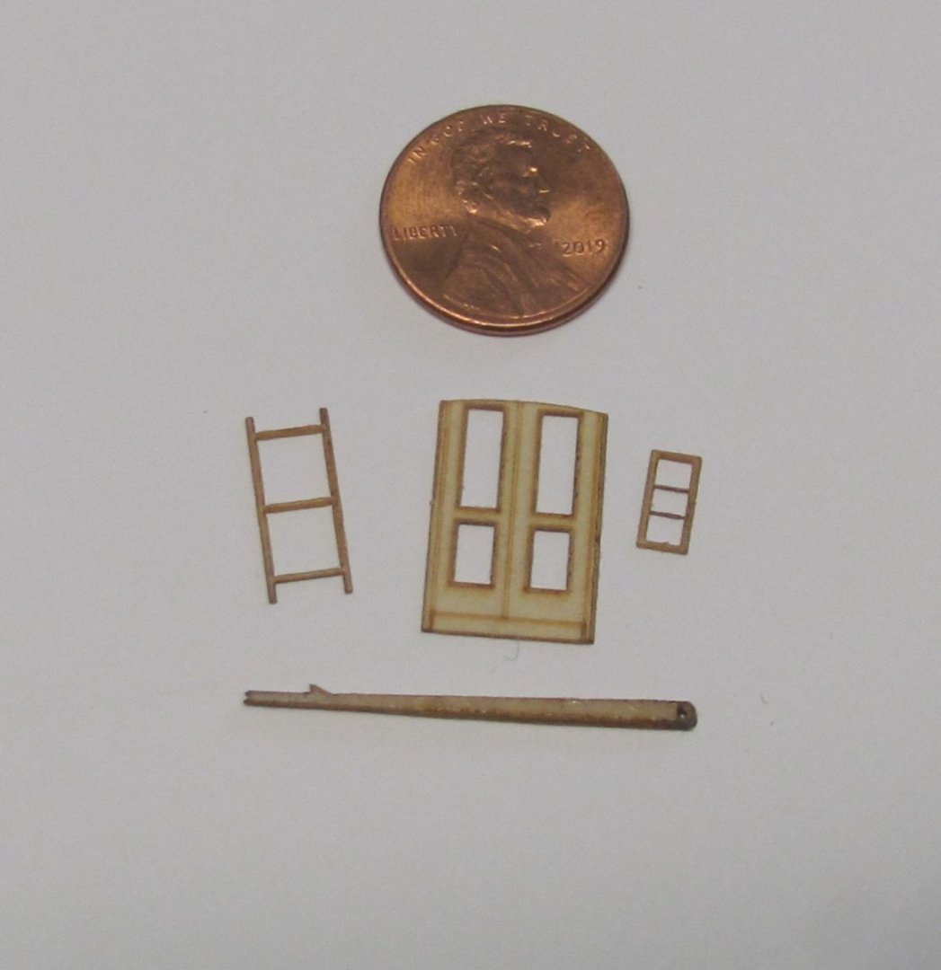
-
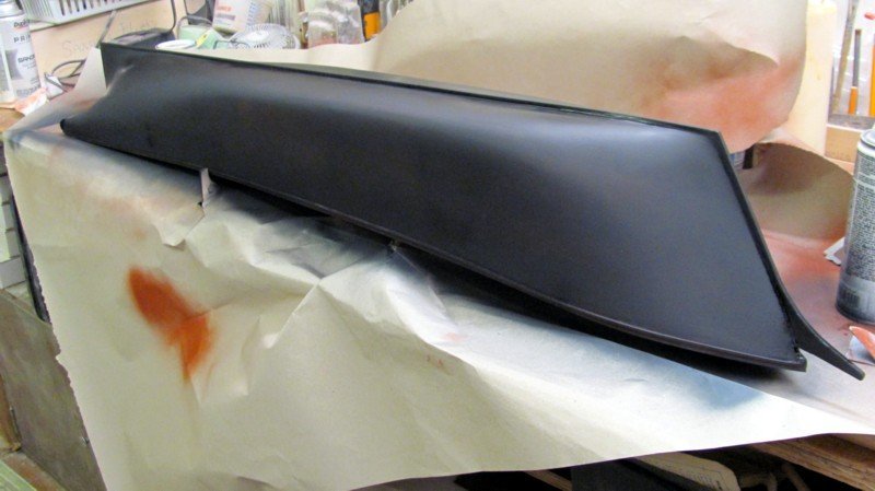
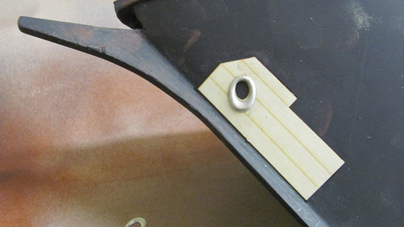
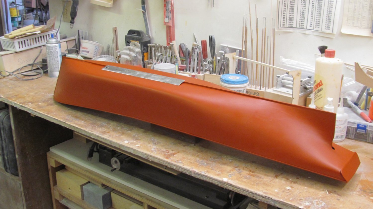
Black primer on this morning, along with the anchor chafing plate and hawse lip. Chafing plate is laser-cut .015". laser board
- 194 replies
-
- 11
-

-
This weekend, I was looking at the chock rail photos and something didn't look right. I finally figured out that I had put them too far inboard. Duh! I redrew them on Sunday and had Shane recut them this morning. It only took a couple minutes to strip off the old ones and install the new ones. Much happier now. 11 Seen by 8 Like Comment Share
- 194 replies
-
- 13
-
-
The chock rails are now glued down and I've added a spacer forward. It's 3/16" at the bow tapering to 1/8" about six inches aft. A few minutes with a block sander will fair it. The brass pins are just to align the holes.
- 194 replies
-
- 10
-
-
In a rare moment of weakness, I felt bad for the modeler having to drill 250 evenly-spaced holes in the chock rail for the stanchions. The chock rails are now four pieces of laser-cut 1/8" basswood with the holes already there. And, they actually fit the hull... Chock rails are not yet glued down.
- 194 replies
-
- 11
-
-

-
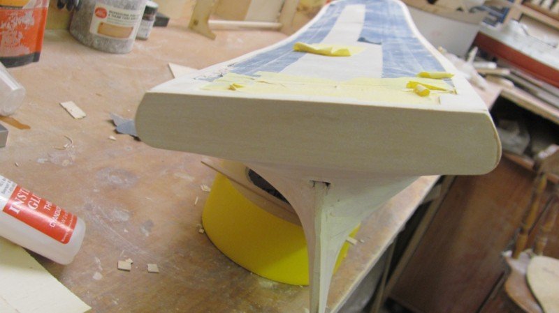
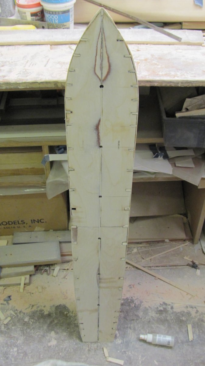
Hull is fully decked and has the waterways added. Transom is shaped with integral "fashion pieces", and the hull now has its third coat of primer. . Deck planking. I used about one hundred fifty 1/16" sq. x 24" basswood strips for the deck. Transom fitted. Deck planks inside the waterways are masked. Third coat of automotive rattle can primer. That's a 12" ruler on the hull bottom to give you an idea of scale.

- 194 replies
-
- 12
-
-
Finished planking the deck today. There are about one hundred fifty 16" square x 24" basswood planks, plus ten 1/16" x 3/32" x 24" basswood mast partners. If a modeler is ambitious and wants to do scale length planks (let's say 40' as one member suggested), it will take about 700 of them. I wiped on and steel-wooled a couple coats of shellac, then added the laser-cut waterways. Tomorrow, I'll finish fairing the hull and maybe put on the keel, stem, and rudder post. The waterways actually fit the hull with just a tiny bit of tweaking! After this photo was taken, the transom was shaped to match the curve of the waterway.
- 194 replies
-
- 11
-
-
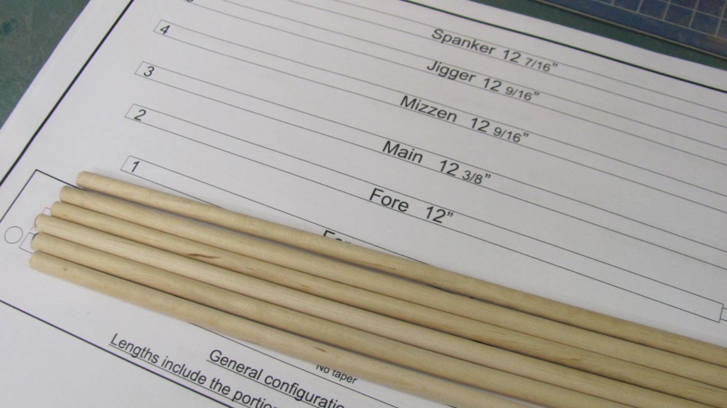
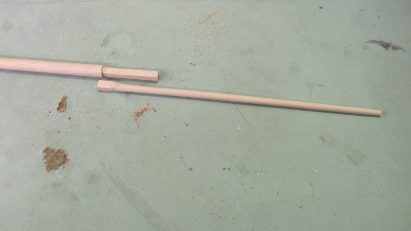
Cut the six lower masts to length and squared off their heads. Made the first topmast, as well. The latter is made from 3/16' square stock that has to be rounded and tapered. It will have a slot for the fid.
- 194 replies
-
- 12
-
-
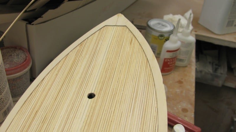
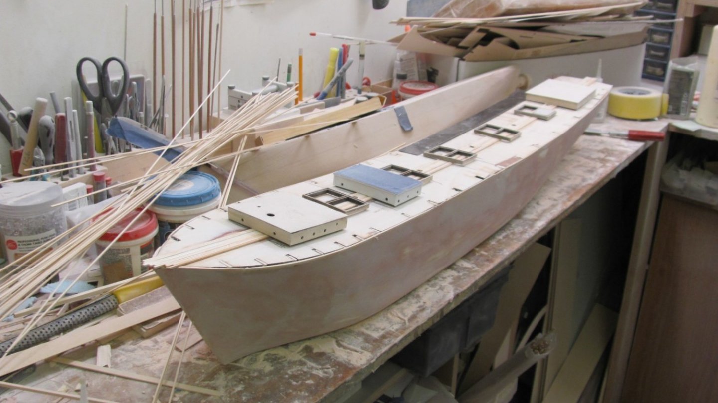
WYOMING hull is planked and broken free from the building board. I've laid the ten 1/16" x 3/32" mast partners and am now planking the rest of the deck with 1/16" square basswood. It'll take about 200 strips to plank the deck. The hull took about one hundred 3/32" x 1/4" strips. My bench is about 36" tall, so... This is just after I broke the hull away from the building board and sanded the subdeck and bulkhead extensions flush. Laying the first planks of the mast partner. They need to be absolutely straight along the centerline or the rest of the planks aren't going to come out right. Mast partners on and the deck houses and hatches just set in place so I can see where to end the plank strips.

.thumb.JPG.ddfb6b7262749adf5117d83b04260e60.JPG)
- 194 replies
-
- 10
-
-
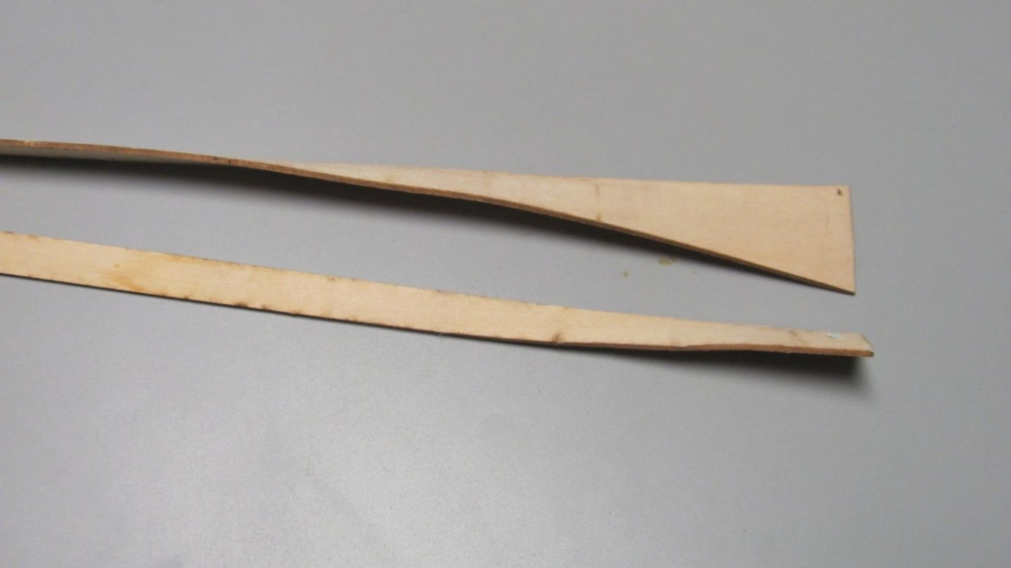
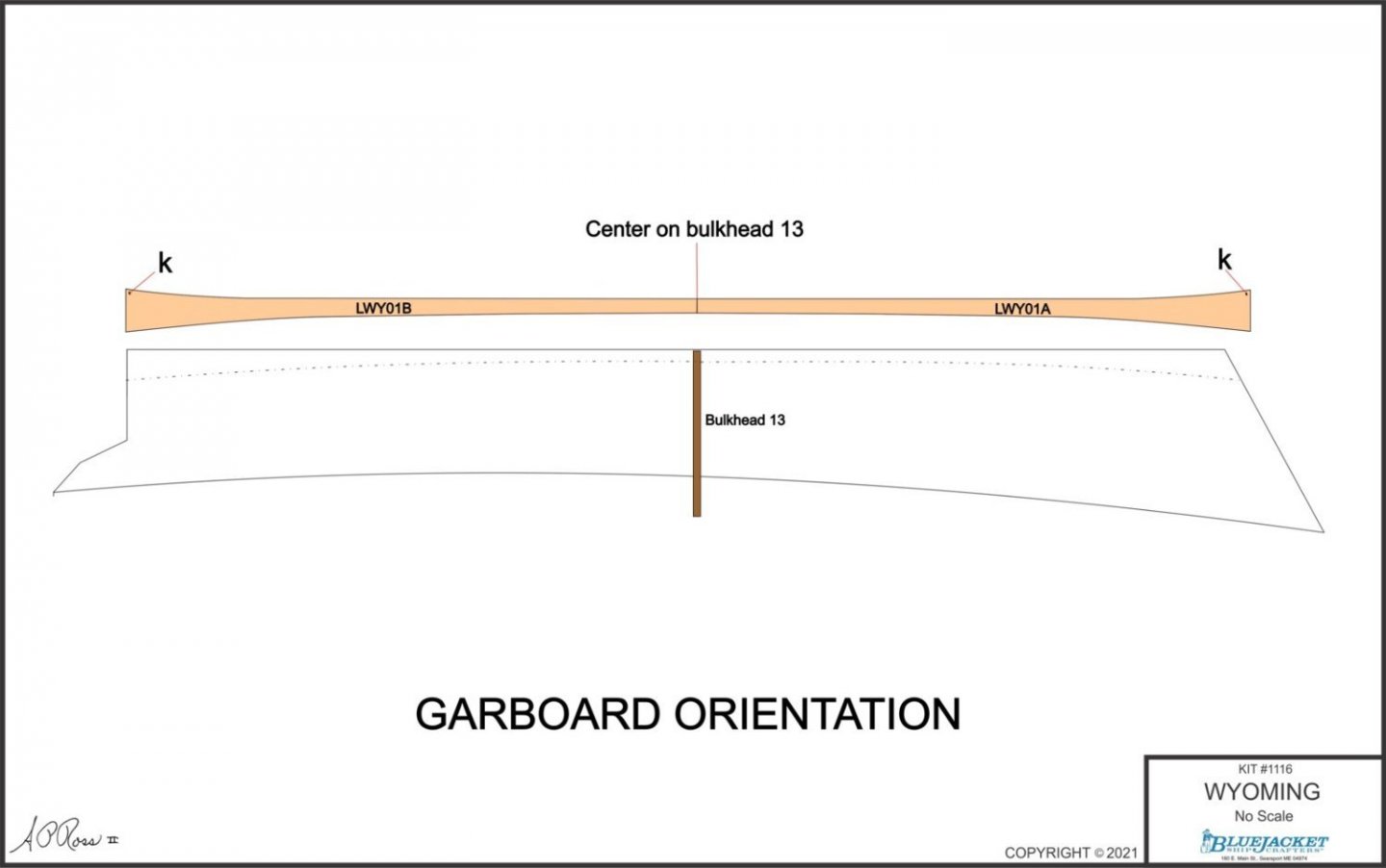
The garboards are two laser-cut pieces per side. The aft portion in particular takes quite a twist, so soaking and clamping is pretty much necessary. Because of the relative symmetry of the curved portions, each garboard has a small "k" lasered into the edge that meets the bottom of the keel.
- 194 replies
-
- 12
-
-
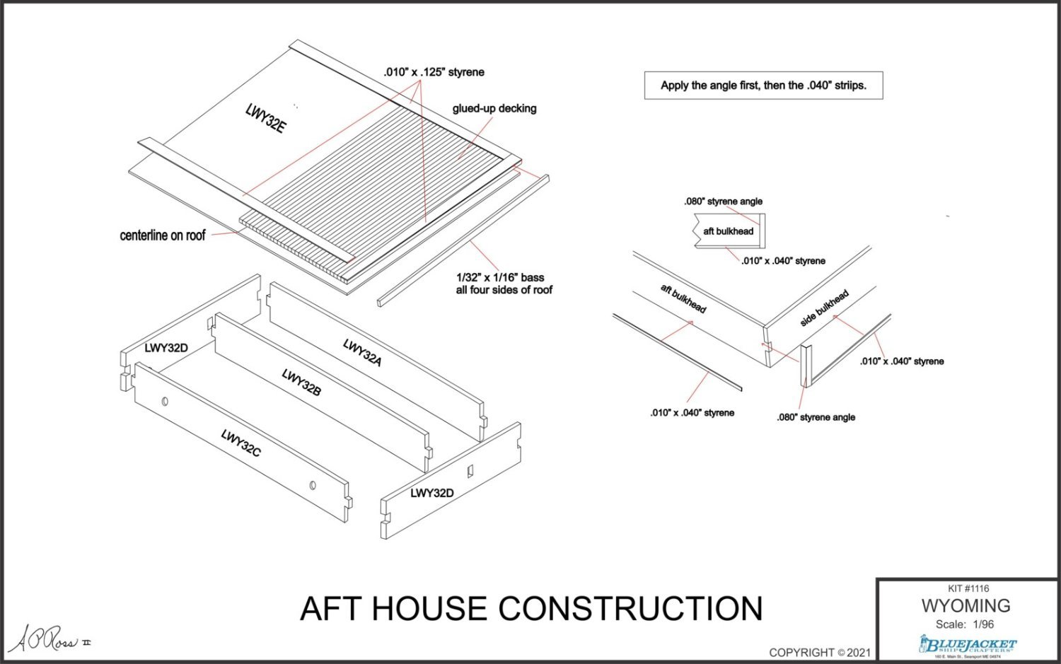
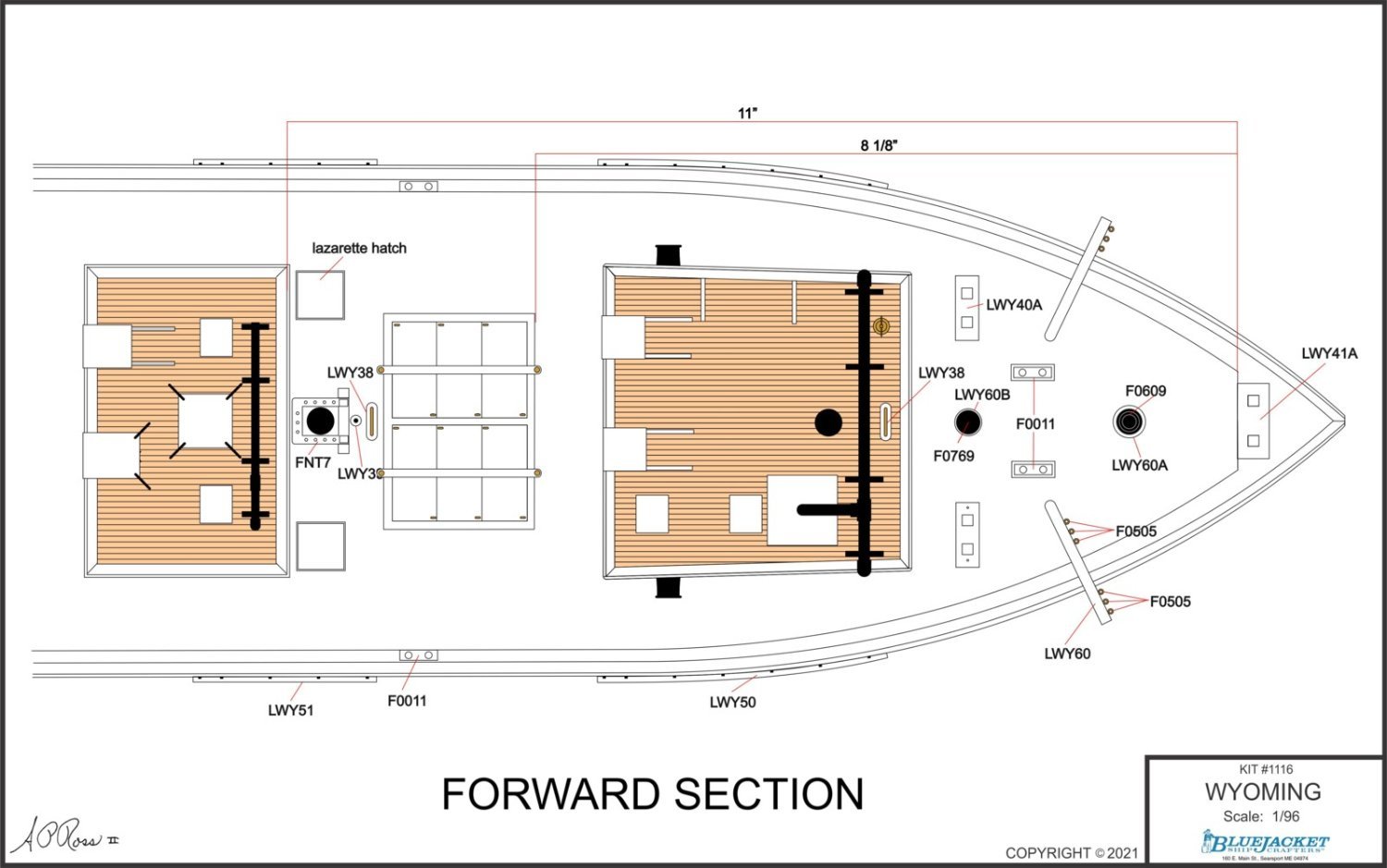
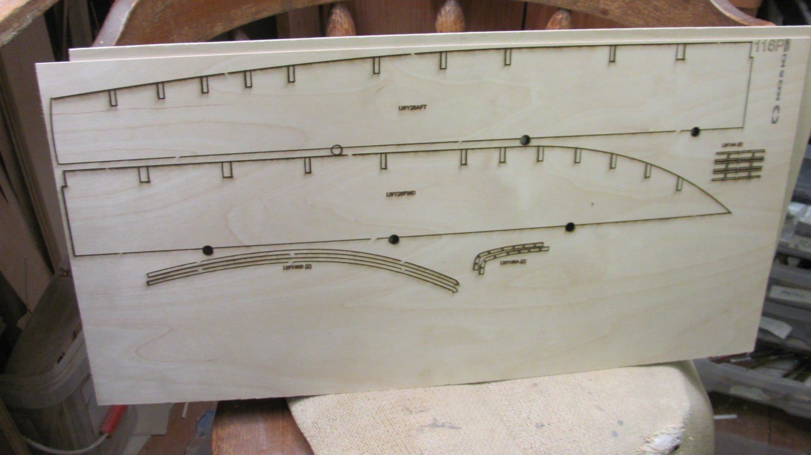
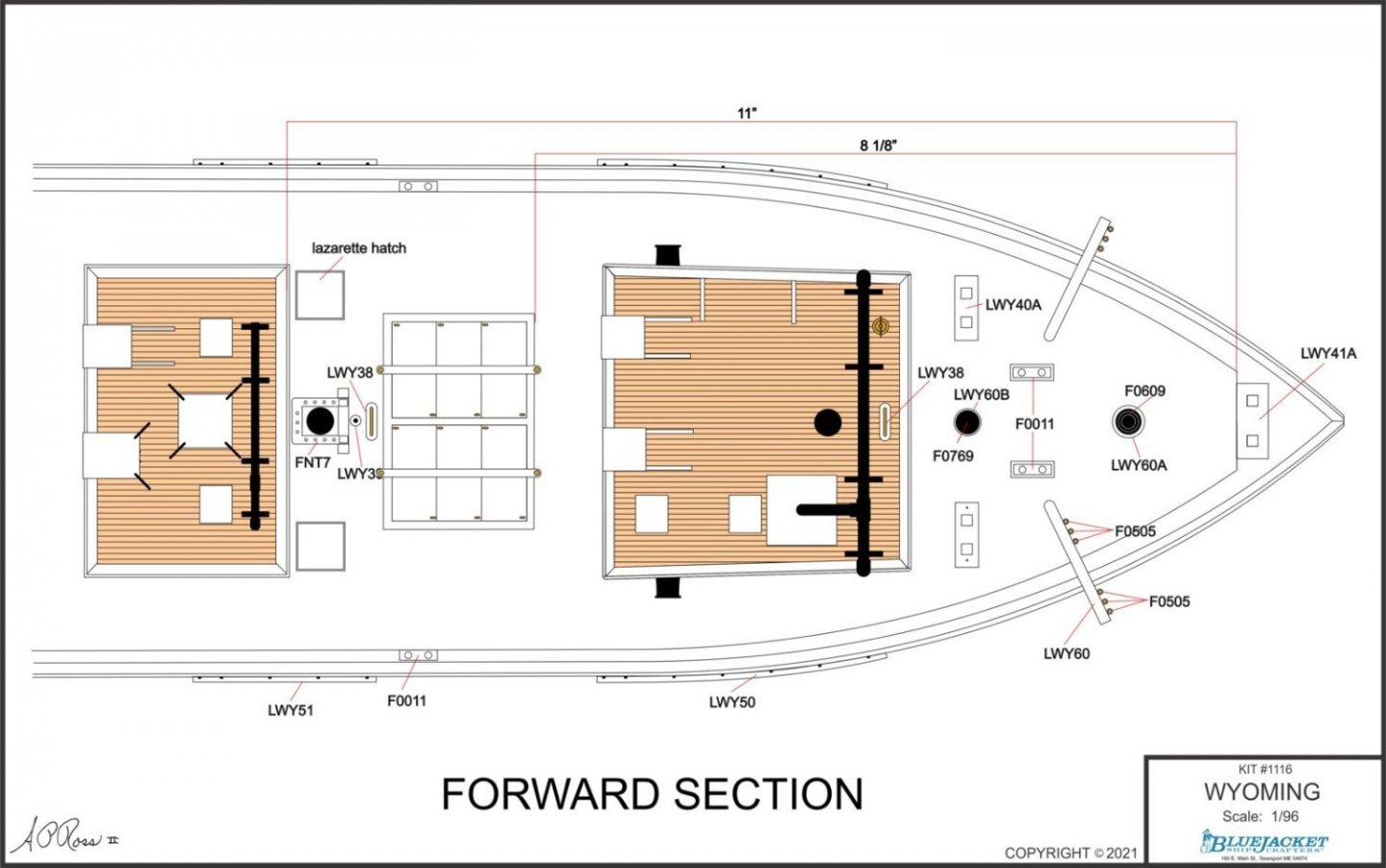
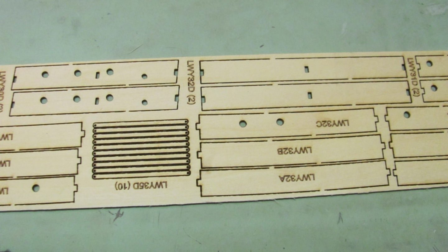
Work continues on the WYOMING kit. I finalized the shape of the laser-cut garboard planks today, soaked them, and clamped them in place to dry. Will start planking tomorrow. Here are a couple more of the 11 x 17 plan sheets for the plans booklet.
- 194 replies
-
- 10
-
-
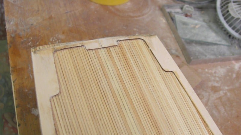
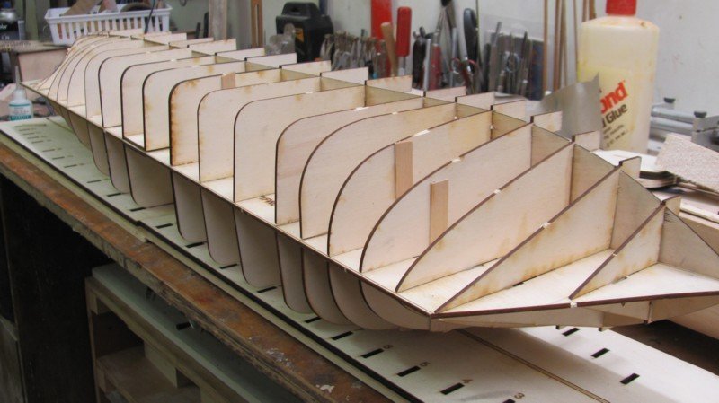
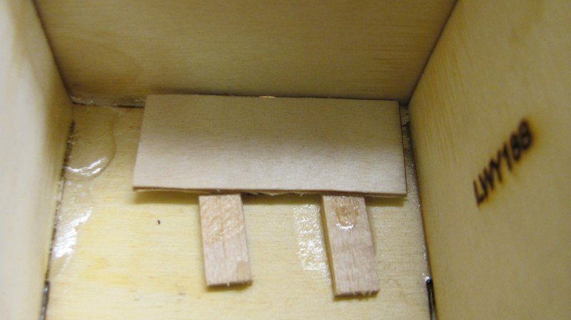
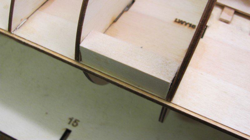
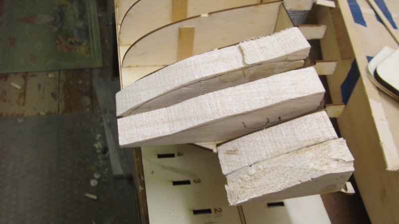
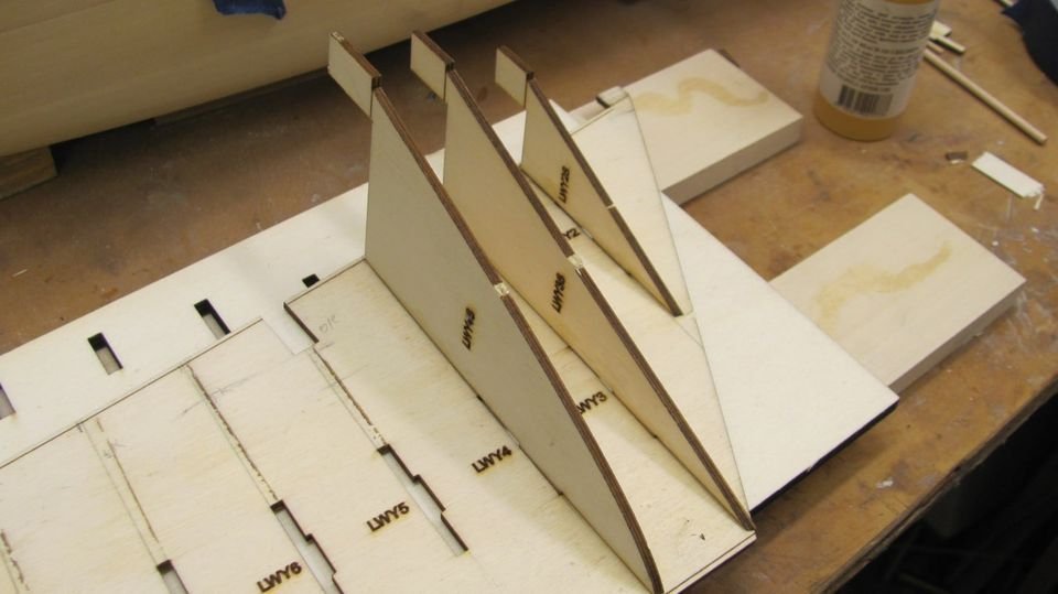
So far this morning, I've attached all of the bulkheads, subdecks, filler blocks at the bow, and the keel stiffeners for the pedestals. Bulkheads and subdecks in place. . Bow filler blocks glued in place. Stern will also have them. They will be faired with the bulkheads once the frame is glued to the building board. The mast slots are boxed in with 3/32" strips and scrap 1/16" plywood. This just prevents sideward movement of the masts once they are stepped. A mahogany cradle is included, but for those wanting to use pedestals, 1/2" square stiffener blocks will be glued to both sides of the profile at the desired position of the pedestals.
-
Plans - keep in mind that the original kit plans were drawn decades ago when customers were closer to being scratch-builders than assemblers. With today's kits having lots of preshaped laser parts, photo-etch, resin, etc., they much more assembly-oriented. Consequently, the plans have to reflect the many preshaped parts to help the modeler succeed. Photo sets - When building the display model of all our kits, I am also fitting the preshaped parts to validate them. Because many of us (me included) are visual learners, I found it useful to take photos of as many steps as possible to get a feeling for how things were working out. Making them available to the modeler seemed like a natural thing to do. Kit designer - My Dad was a naval officer and the first model kit he bought me back in the early 1950s was a ship model. Over the next few decades, I assembled a lot of plastic ship and aircraft kits and became very interested in how things were put together. That's when I started to draw them. Life happened and, like most of us, I had to work for a living to support a family. While working on my PhD in the late 1970s, I started drawing plans for small naval combatants (PTs, MTBs, MGBs, etc.) based on the actual yard drawings and selling them to modelers. After a number of years designing technical training for nuclear power and teaching technical writing in a college, I got tired of the corporate and academic worlds and started building custom ship models. BlueJacket was just down the road, so I was a frequent customer. I designed my first kit for them (80' ELCO PT) in the mid-1990s and soon was doing it on a regular basis. Eventually, I was doing it full time. So far, I've provided those services (as an independent contractor) to three different administrations (the Hammers, the Margers, and the Damucks) and plan on doing so until I am physically unable or have croaked...
-
Boucher became BlueJacket in the 1970s. We still have that plan in the drawers out back. When I developed the existing kit of PERRY, I looked at it and compared it to Chappelle's drawings and some other references. The old kit's armament wasn't consistent with my references, so that was changed, as was most everything else in the original kit.
-
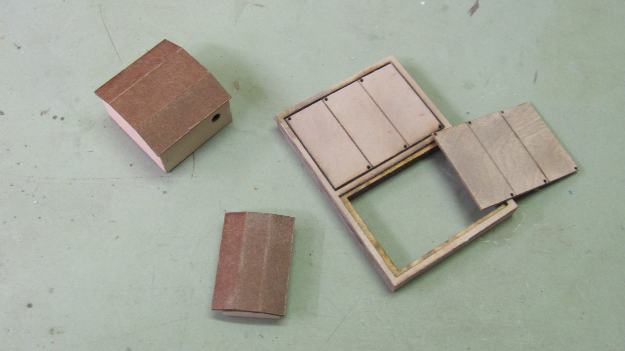
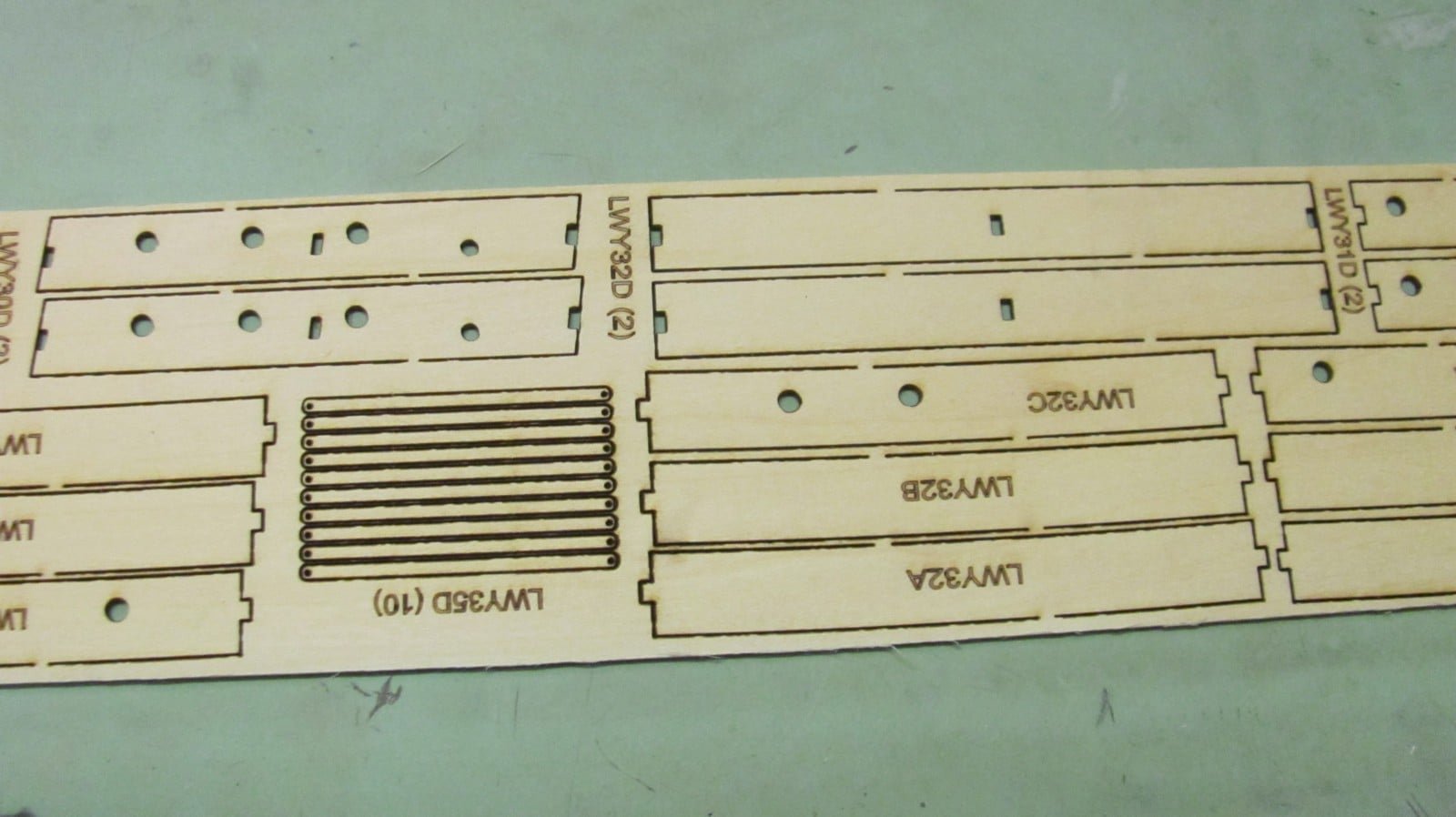
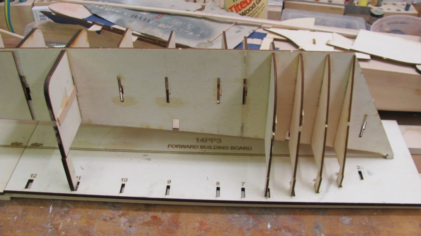
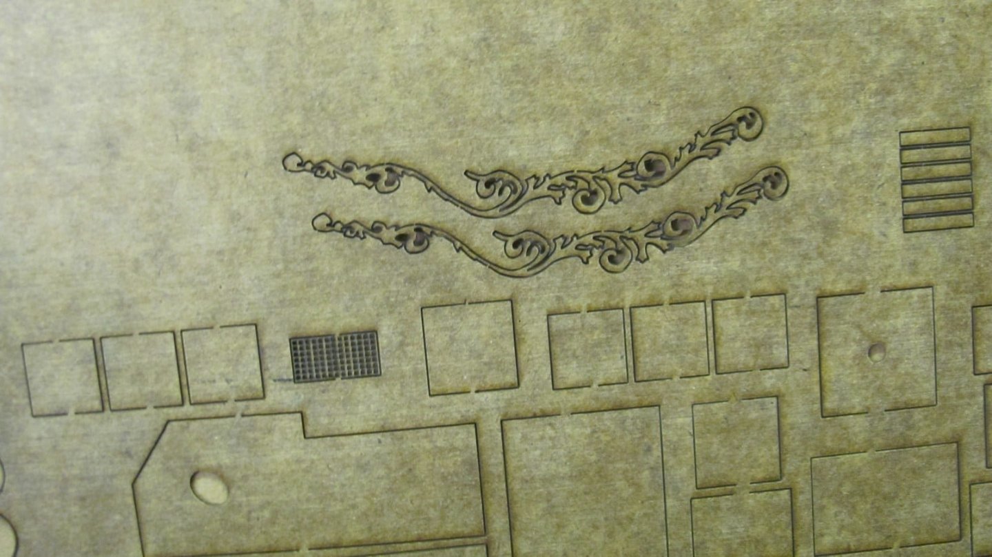
OK, back on the WYOMING kit development after a long hiatus. I've added a laser-cut building board to it and am currently assembling the bulkheads to the profile. Am making adjustments to the bulkhead shapes as they are assembled and revising their laser drawings - 1/32" here, 1/64" there, etc. The building board. It will be used after the bulkheads are assembled to the profile and will provide a stable base for planking the hull. Laserboard scroll work. First few bulkheads in place. . One side of the sub deck(s). Some deck house components. The long bars are hatch battens.

- 194 replies
-
- 12
-
-
Schooner plank length
alross2 replied to alross2's topic in Building, Framing, Planking and plating a ships hull and deck
WYOMING, Percy & Small, 6 master. -
At the turn of the 20th Century, were deck planks generally cut to standardized lengths or did the yards use random lengths to get the most use out of the lumber? Al Ross
-
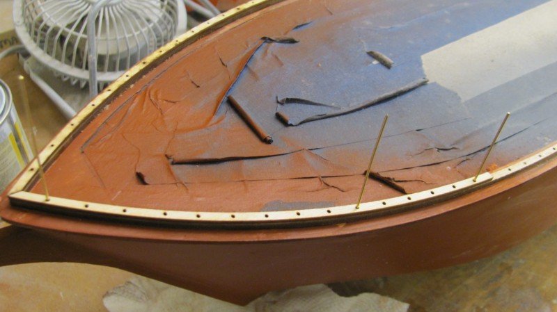
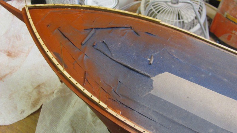
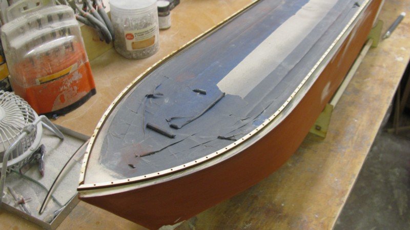
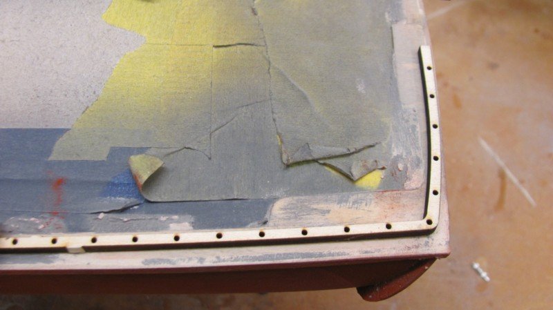
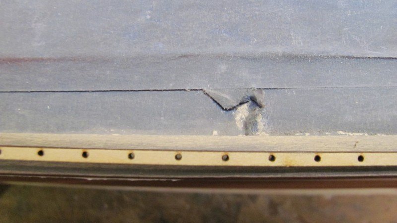
I think the angle of the photo makes it look worse than it actually is. Here's a similar photo of this area of the display model for the kit, but from a shallower angle. I would agree that filling the outside a bit and doing some light shaving on the inner side would resolve your concern. Al Ross
.JPG.17fb4c19824c415053c57d9ecfe8316a.JPG)
-
"Cheating" with alternative materials?
alross2 replied to Brewerpaul's topic in Wood ship model kits
I don't remember the source BJ uses offhand, but can find out for you. Essentially, it is resin-infused paper. When used with a properly set laser, it can produce extremely fine detail without burnout. The thinnest I've seen so far is .011". I normally use .015", .025", and .035", but think you can get it up to .060". This is the pilot house for OREGON. It is two layers of .015" laserboard bent around a former that will be included in the kit. When I tried it in 1/64" ply, many of the vertical pieces of the lower panels simply burned out. With the laserboard, there's hardly even any scorching on the back side.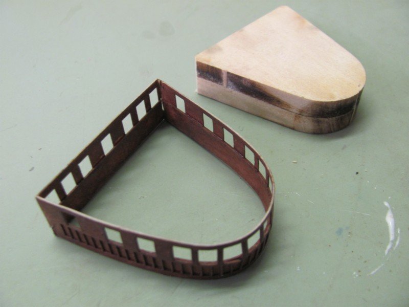
-
"Cheating" with alternative materials?
alross2 replied to Brewerpaul's topic in Wood ship model kits
If it works, use it! In the kits I develop for BlueJacket, I've gone to laser board for many applications where I used to use 1/64 and 1/32 ply. It bends easily, has no grain, and produces very delicate parts with sharp edges. -
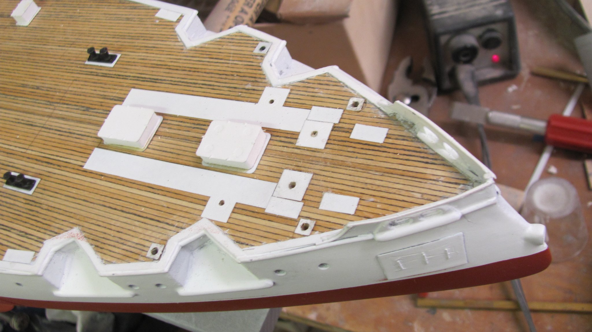
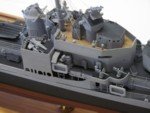
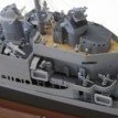
Bow section with most of the bases for the various bits and pieces.

-
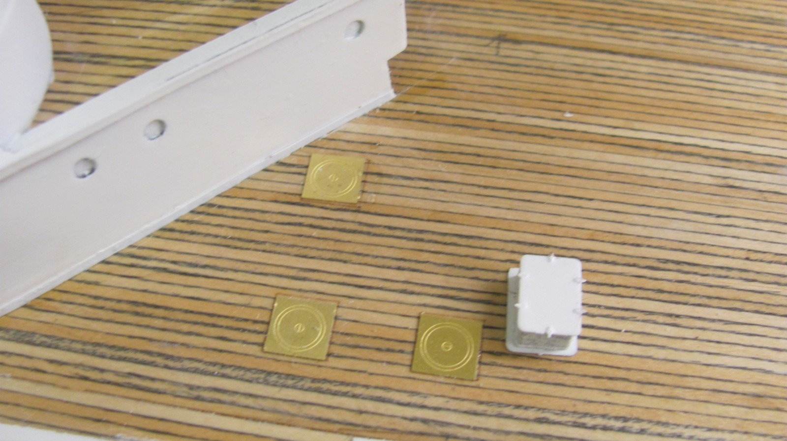
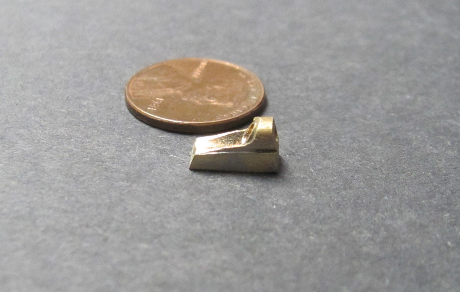
It never fails. We have two nice chain stops in the fittings - neither one fits OREGON. So, I made up a brass master this AM from brass tube, brass channel, and solder. There will be four per kit.

-
The best way to remove it is not to get it... I don't get it very often because I double or triple mask, first with pin striping tape (1/16' or 1/8"), then an overlap of 1/4" tape, then another overlap with low tack painter's tape (and paper if it's a large surface. Still, stuff happens sometimes. The underbleed I normally get is between the hull and a bright finished deck. In most cases, I use a very sharp #11 blade and cut alongside any objects against which the underbleed rests. This gives a nice sharp edge to end against when scraping. Then, depending on the size of the area around the paint, I scrape with the grain towards the sharp edge using a variety of chisel blades and a razor blade. You need a gentle touch and to keep the blade vertical. If it's paint on paint, now you have a definite problem. If it's gloss paint and the base coat is well cured, you can use a Q tip dipped in a mild thinner and lightly swab aqay the underbled color. Sometimes you can use automotive polishing compound and a soft cloth on some paints, as well. In all probability, with a paint on paint problem, you're probably going to have to remask and repaint. FAIR WARNING: I seldom brush paint any large surface. Generally, I use an airbrush and sometimes a rattle can. Consequently, I'm not sure how well this would work with a brushed surface.
- 47 replies
-
- 11
-
-


.JPG.48ff00dd44c0479dc5b407ddf3afe111.JPG)