Stuntflyer
-
Posts
1,198 -
Joined
-
Last visited
Content Type
Profiles
Forums
Gallery
Events
Everything posted by Stuntflyer
-
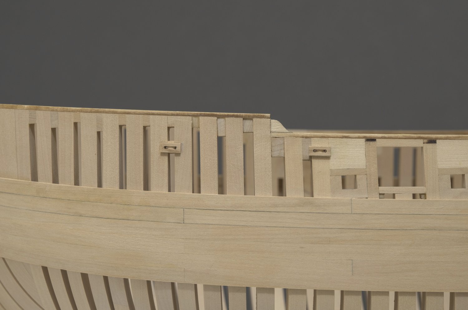
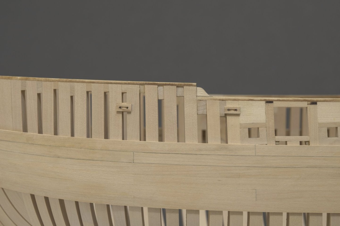
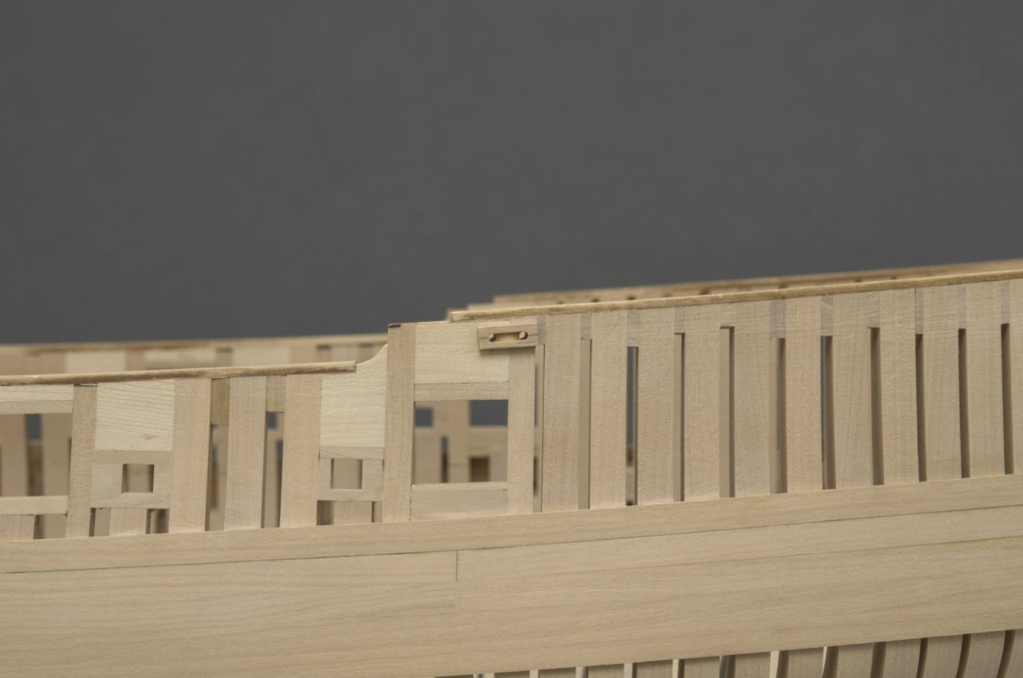
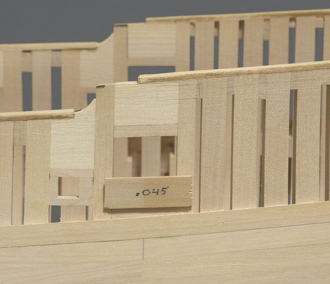
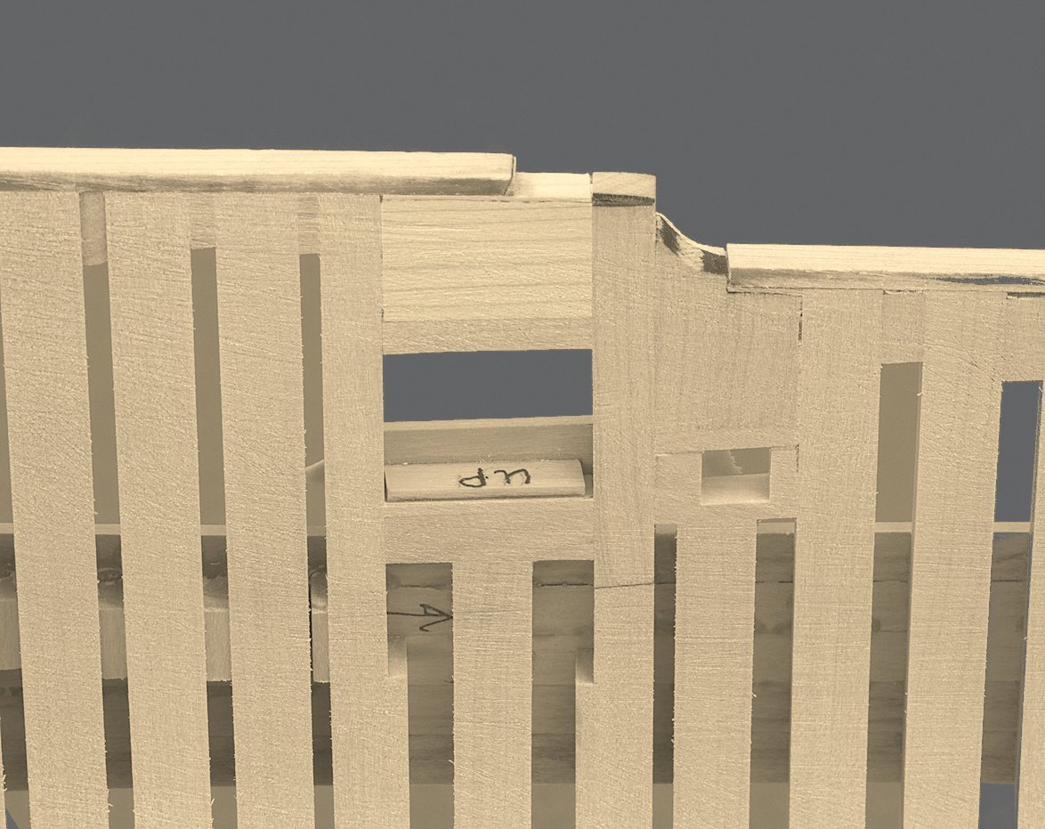
 Fixed blocks This weekend seemed to be a good time to get started on the fixed blocks. Six are on the ship with the two really small ones near the transom completed, but off the ship. I'm not sure if I will add them before or after planking that area. I decided to scratch them, using the mill to make the slot between the two holes. When I originally drew in the upper wale location with the hull template, I also marked the location of the blocks. I could have gone with that and it would have been fine. However, since I started the build I've tried to measure off the plan sheet whenever possible. So, here again, that's what I did. I only needed to measure and drill the position of one of the two hole locations for each block. Then it was just a matter of establishing the distance for the second hole while aligning the top of the block parallel to the shear. Here is how I made the tiny rounded shape representing the sheave. It's only .020" deep. Mike
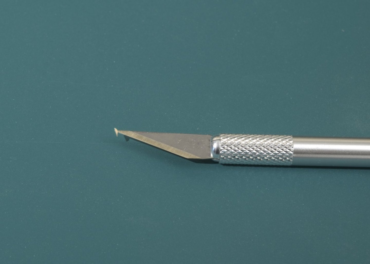
-
Very nice! That's pretty much how I imagined it would be done. You mentioned that you didnt want to go with shiny metallic copper paint. I wonder how metallic paint would look with Dullcote on top.
-
Chuck, you've got some really nice detail going on here.
-
Rusty, Chuck, Thank you! Keelson I've been working on the keelson for a while. A little bit here a little bit there while fairing the frames. I went with boxwood as usual and milled scarph joints. I used 30lb (.023) black mono for the bolts. I noticed that the keelson would slip and slide a bit on the frames so I pinned it in two locations. This enabled me to center it port and starboard while saving a lot of eyeballing when gluing it down. Mike
-
Looking very nice, Erik.
-
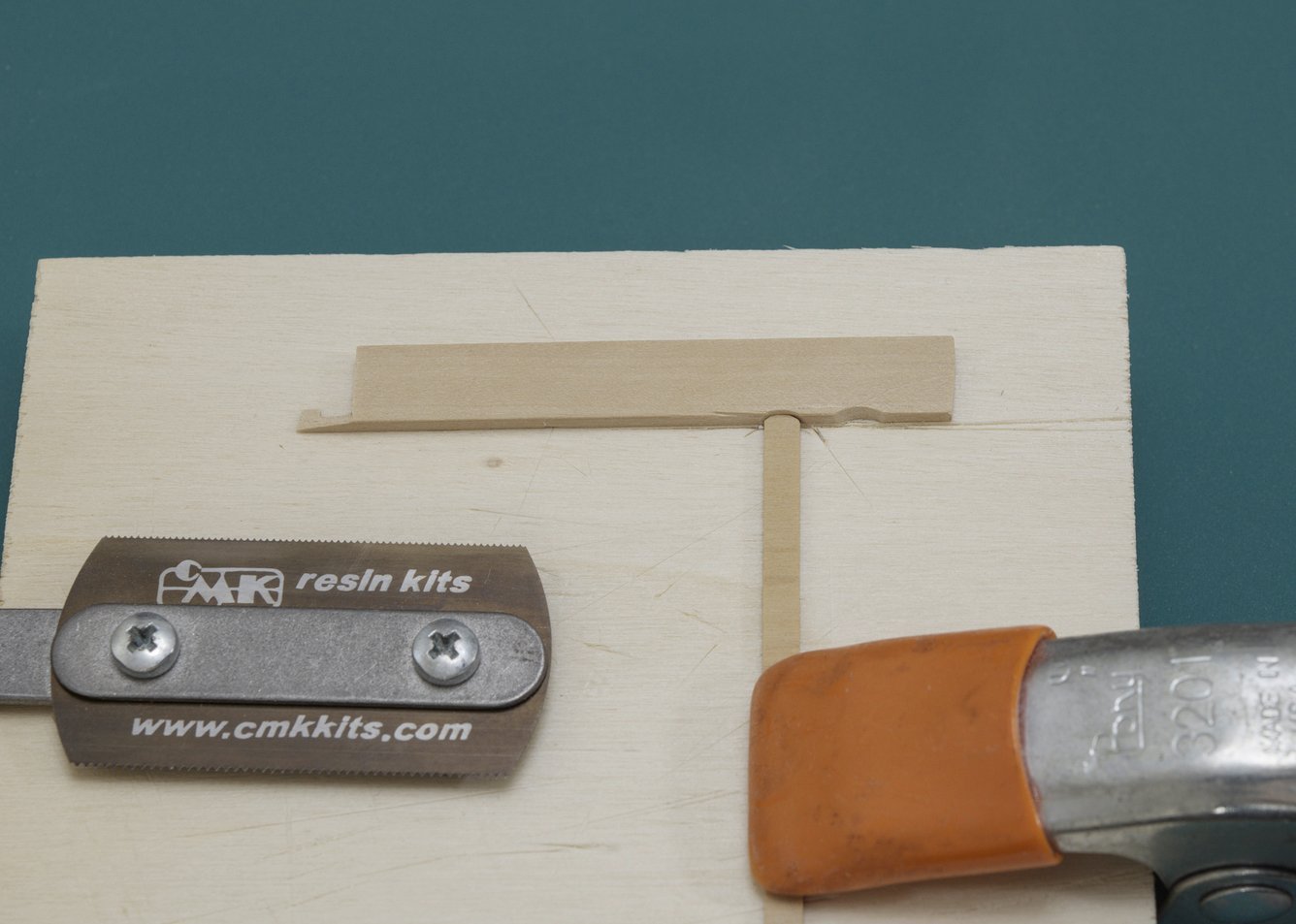
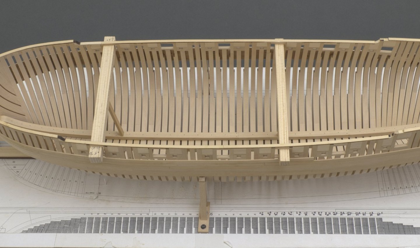
Hull planking Fairing the outer hull was fairly straight forward. There is plenty of extra meat on the frames which gave me lots of wiggle room. The fairing cap edge should remain untouched, if at all possible. Easier said than done! Final sanding was done with 400 grit. Btw; I totally forgot to take some photos of the outer hull after the fairing was completed. Sorry! Once everything looked good I added the first strake (the upper wale). This was done with three planks. I did my best to eyeball the run as I added each plank and not to strictly rely on the drawn line which I made from Chuck's hull template. From there on it was just a matter of adding the two remaining wale strakes and a few more strakes above the upper wale. I also added the small filler piece which goes between the lower wale and the square tuck. With the added support given by these strakes, I decided to fair the inner hull. This ended up being more time consuming than I thought it would be. It took me several days to complete the work. Working the bow timbers, even with a Dremel or 80 grit, was slow. Once I was close I switched to a miniature curved scraper to smooth out the work. You can see just how thick the wood was in places. When fairing the area around the lower gun port sills, I found that a simple depth gauge came in handy. Including the 3/64" outer hull planking, the width of the sill should be 3/16” or maybe a hair less. I made this simple “T” shaped jig that I could place against the frames and then mark the width of the sill from inside the hull. Ready for the keelson Mike

-
Chuck, very nice! Quick question. Is that bulkhead removable so that it will go in after the deck is laid?
-
Drawing center lines
Stuntflyer replied to Stuntflyer's topic in Modeling tools and Workshop Equipment
My apologies for not at first seeing Bob Cleek's post above and only those below his. My objective was to find the tool that would pencil mark the center at any width and be able to draw a center line over the length of wood. It appears that the Lee valley one, although not auto centering, would be the type I was looking for. It has the ability to mark and draw a center line even if the wood has a curve to it. -
Drawing center lines
Stuntflyer replied to Stuntflyer's topic in Modeling tools and Workshop Equipment
Gregory, I like the tool. I'm also wondering if the smallest one would work. I'll wait a bit to see if there is a smaller version out there. -
Drawing center lines
Stuntflyer replied to Stuntflyer's topic in Modeling tools and Workshop Equipment
Thanks, Kauz. I've seen that before. I was just wondering if there was a manufactured center line marker available online. -
Rather than using a compass, is there a small tool which can be purchased online to draw a center line down the length on 1/4"-1/2" wood strip? Thanks, Mike
-
Looking so nice, Chuck. A whole new look for Speedwell.
-
Beautiful work as always! It's seems to be coming together so quickly.
-
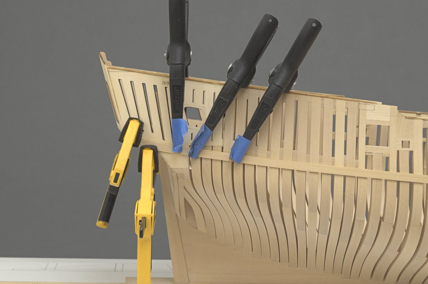
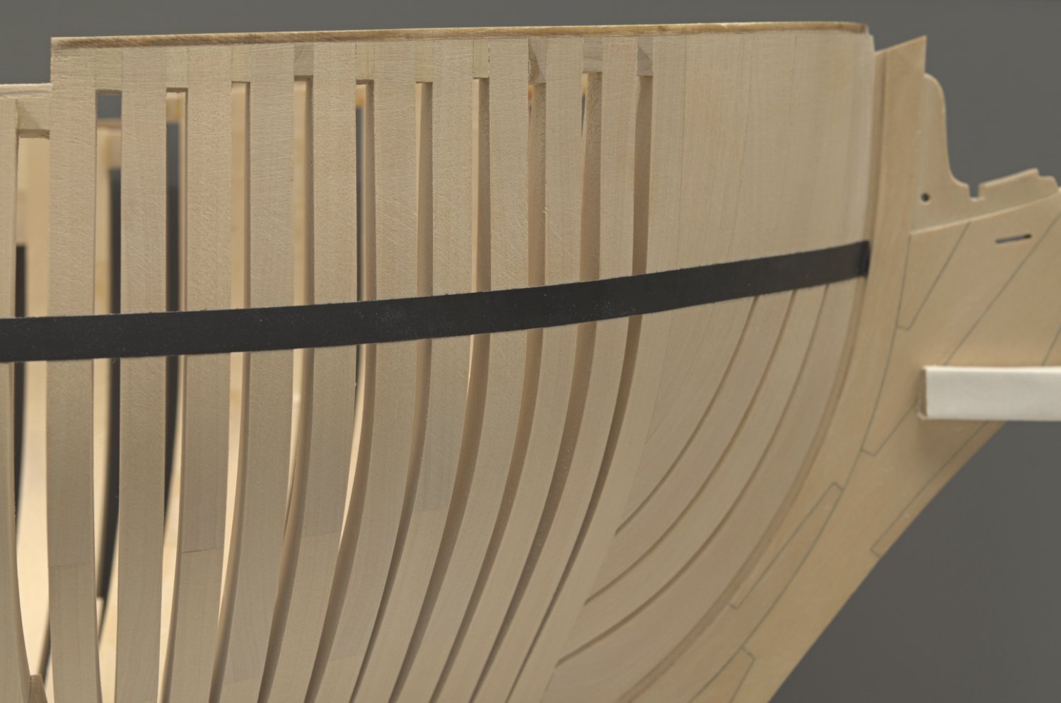
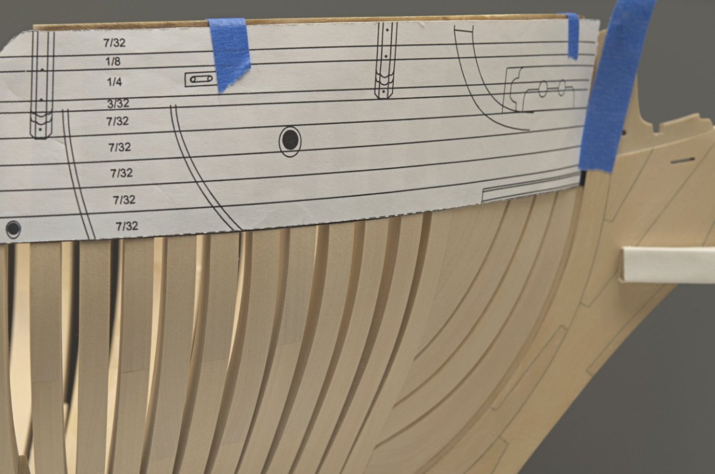
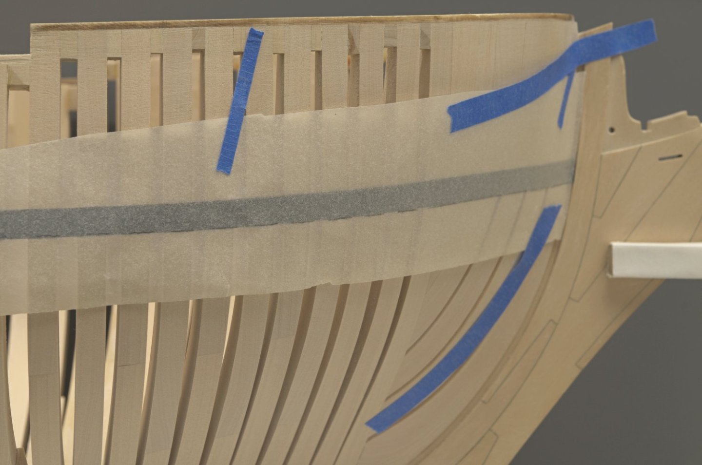
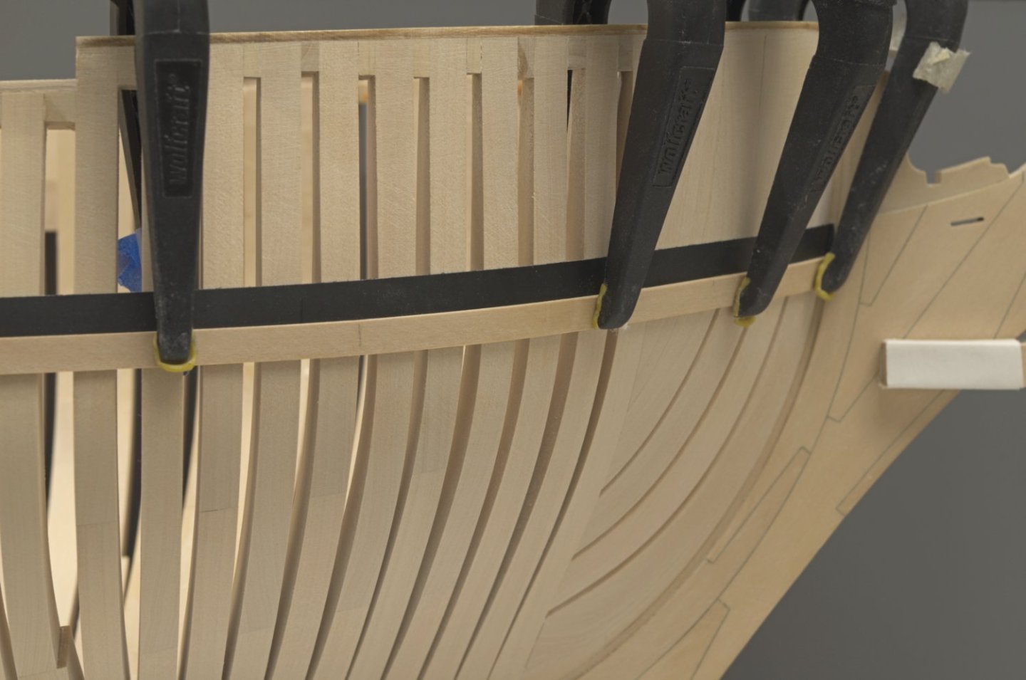
Hull planking (prep) One of the things I've been wanting to do was to see whether or not I could get away without having to spile the hull planks from 3/64" sheet. I was hoping that I could just edge bend boxwood planks to match a spiled shape. With that in mind I ran a test to see if indeed it could be done. The sequence is a little off since I thought of taking the photos after some of the steps were completed. I retraced the steps as best I could. For better viewing I have focused in on a smaller area of the hull. The first thing I did was to attach the hull template to my hull. I ran some 1/4" striping tape along the lower edge of the template and then back masked the upper edge of the tape. After that the original layer of tape was removed. You can see a bit of the back masking at the stem. I could have just drawn a line along the bottom of the template instead of using tape. Being a test of only one plank, I didn't want to do that. Hey, that's just me complicating things. Here is the back masking (original taping removed) where the lower edge will line up with the upper edge of the plank. I traced the lower edge of the tape (the shape for the upper edge of the plank). This gives me the shape needed for spiling or hopefully just some edge bending. You should be able to see the pencil marks across each frame. The resulting shape resembles a gentle "S" curve. Something like this. I was able to edge bend the boxwood to match the spiled shape without any difficulty. Clamping the test plank to the hull was done without having to do any twisting or bending. Mission accomplished! Mike


-
Totally, it looks so real. Your artistry is very apparent. Mike
-
Really nice! Doesn't look too difficult to make at all. Mike
-
Thanks, Chuck! I think it's going to be a while before I'm anywhere near where you're at. I still haven't finished up fairing the hull. Now that the fairing cap is on I will work on getting that done. After that I want to start painting the ports. Are there any other options that would work nicely with the friezes other than crimson red?
-
Absolutely, Erik. You should be👍
-
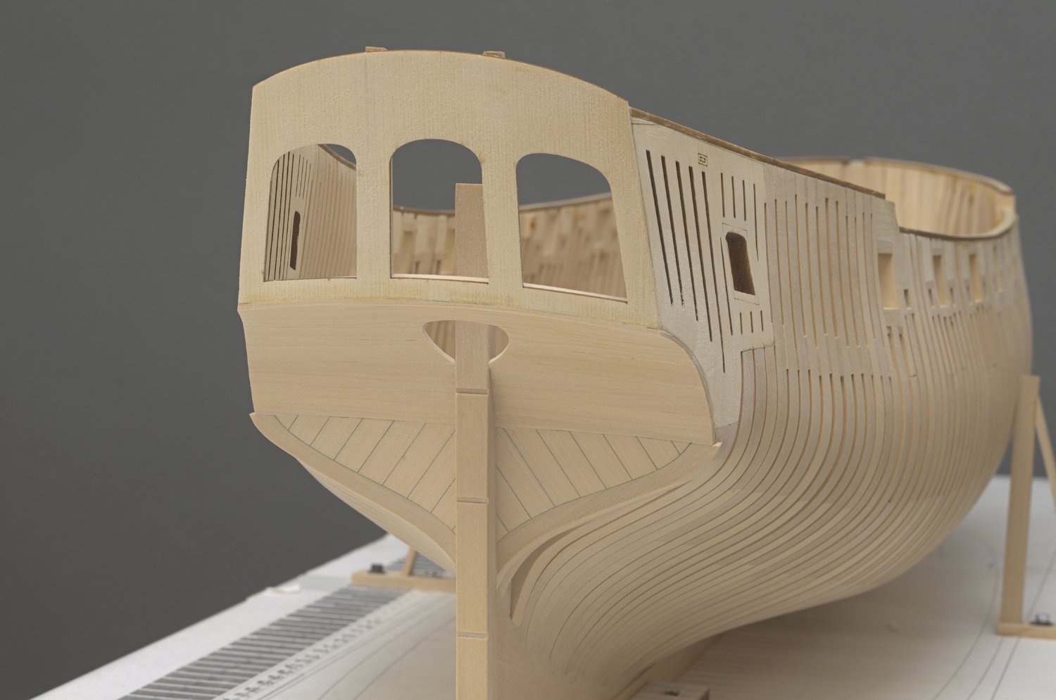
Lower counter I gave a lot of thought towards doing the lower counter in AYC. Unfortunately, I didn't have any sheets on the shelf. I know it all seems pretty straight forward, just a simple planking job. That wasn't the case at least for me. It would have been easier to do this in AYC being that the wood is much more flexible than boxwood when doing this kind of work. After the planks were in I faired a nice rounding into the wood with some miniature scrapers. https://www.amazon.com/Lynx-Mini-Scraper-Set-4pc/dp/B00ICISC2U There were a few areas where the cedar quarter panel was slightly over faired (rounded off) on the lower edge which I compensated for when I faired the outer edge of the lower counter. Mike

-
Great idea, Chuck! as long as the shear is good, then all should work out nicely. I’m gonna take a look at what Greg did on his build. It should be an interesting comparison.
-
I'm happy to see that your back at it again. Looking nice! Mike
-
Thanks guys! Your kind words are very much appreciated, as always. I'm looking forward to getting those first planks on the ship. Something different! Chuck, thanks for the heads up. I added the first counter planks and there was no issue getting the lower edge of counter flush with the square tuck Mike
-
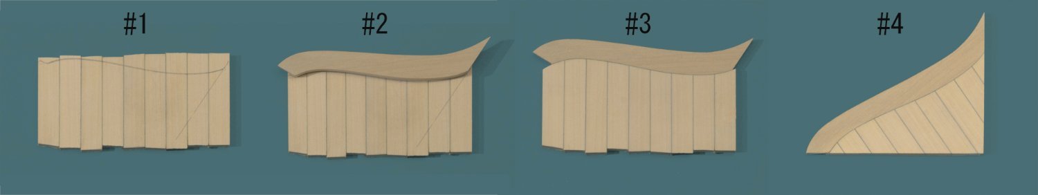
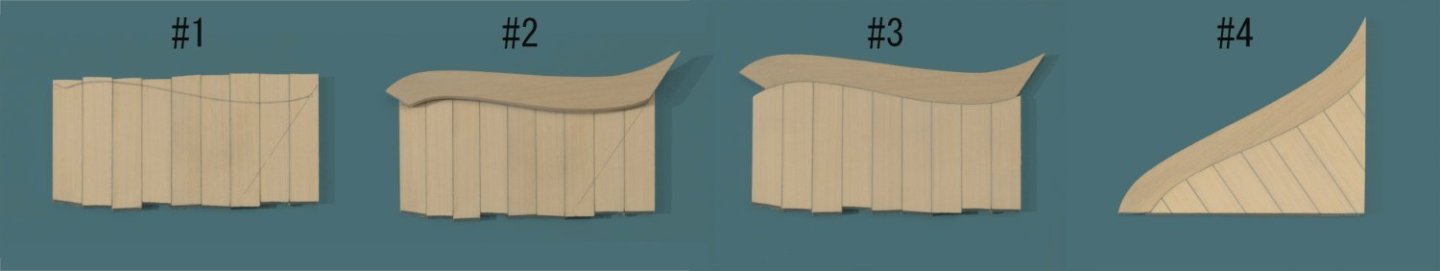
Square tuck I wanted to give this a try at least once before making use of the laser cut versions. #1. I copied the angle from the laser cut piece onto the joined strips. #2. The frame was made and set parallel with the angled line. #3. The curves were done with the spindle sander and disc sander along with a bit of hand work. #4. Almost ready to place on the ship. I Still needed to taper the frame. The most difficult part was trying to get symmetry between the two sides. It's not perfect, but certainly close enough. I was kicking myself when I noticed that the top of the port side square tuck is 1/64" lower at the stern post compared to the other one. Of course this won't be seen once the moulding is on. I left the outer area of the frames without any tapering. There is a tiny filler plank that goes between the tuck and the first strake. I will wait until that's on the ship, so I can sand that area all at the same time. Anyway only one shot at it for this result. Mike
-
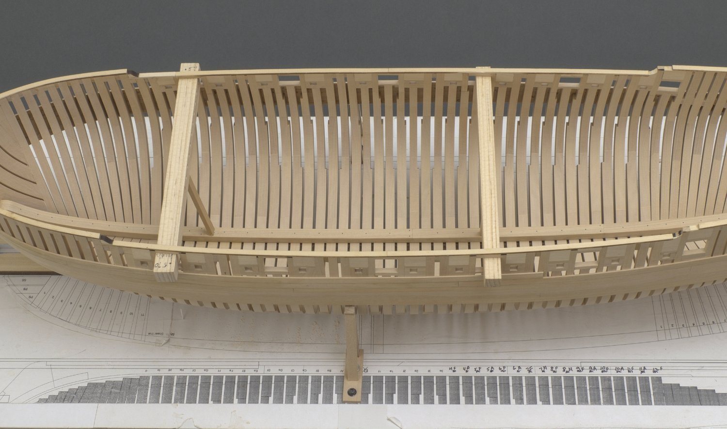
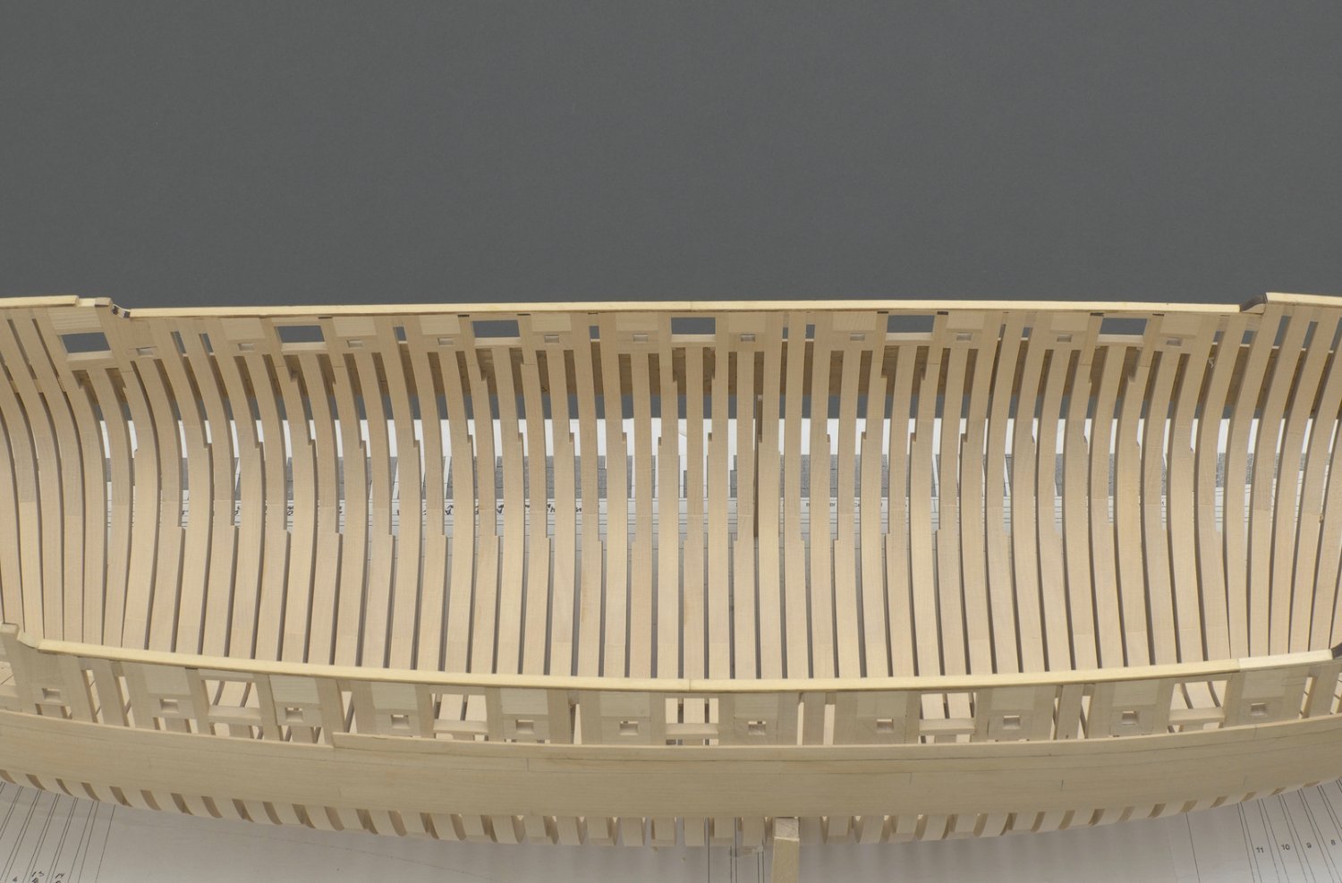
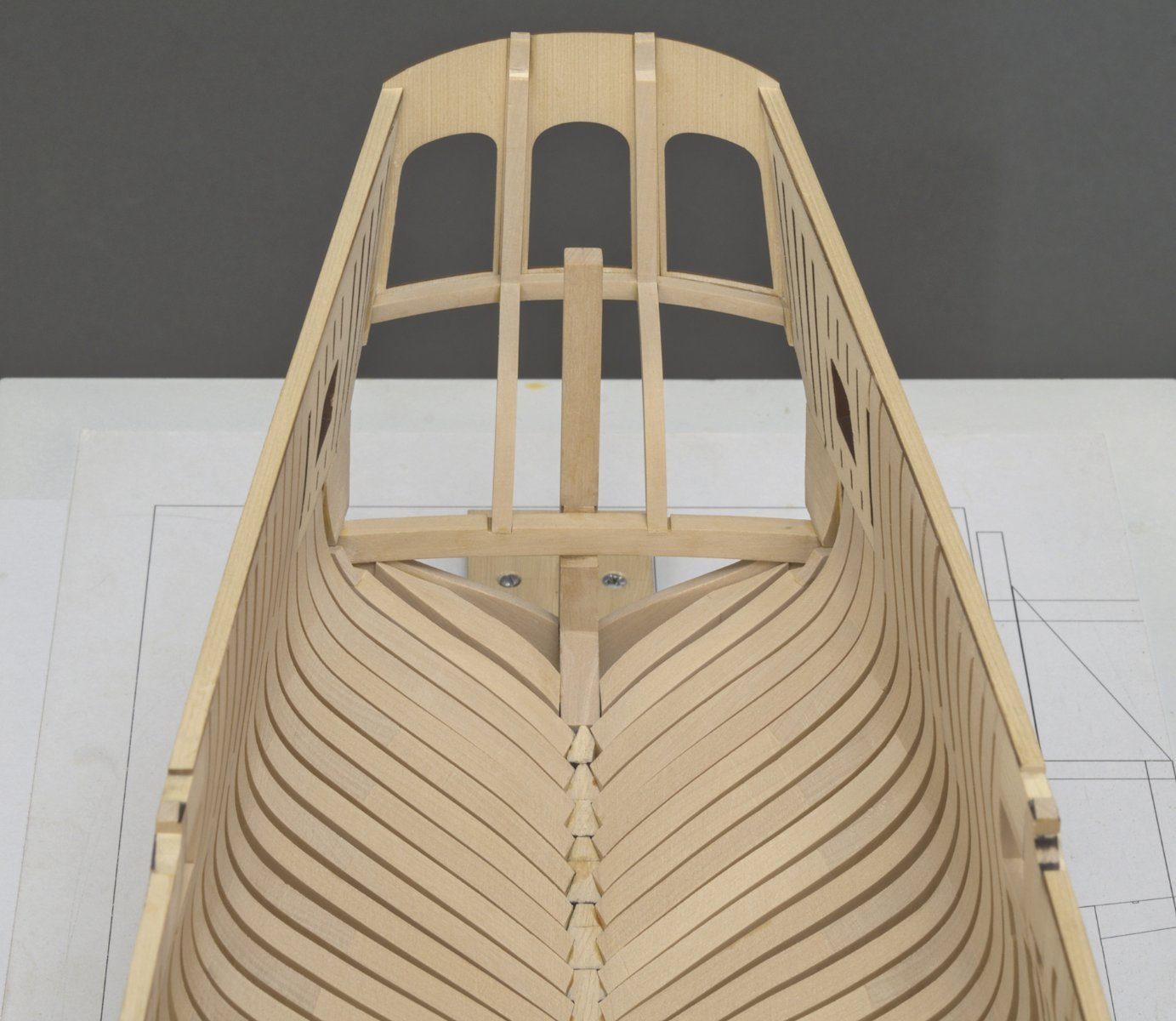
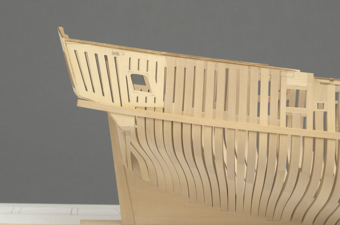
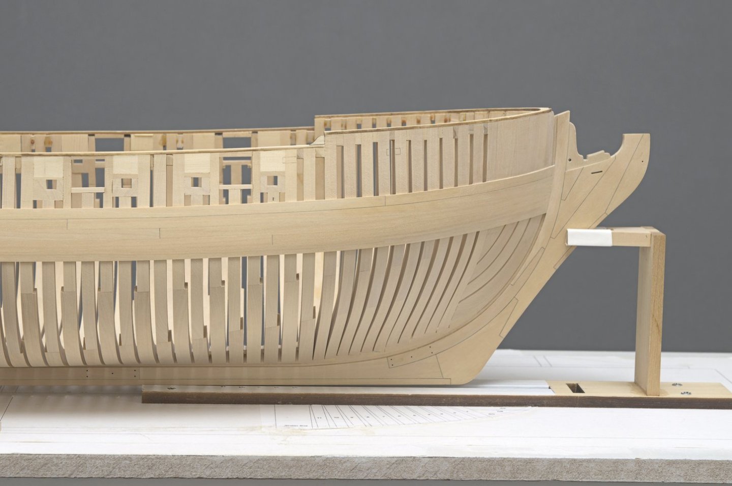
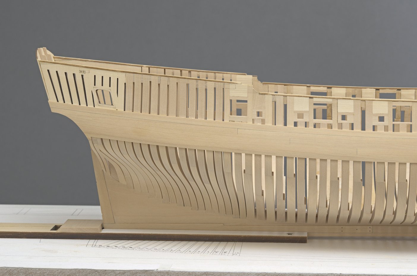
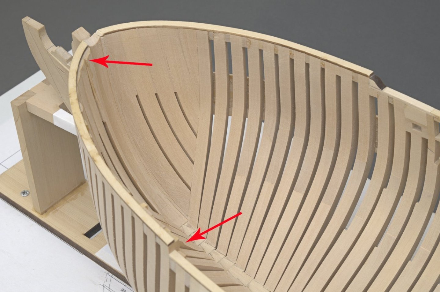
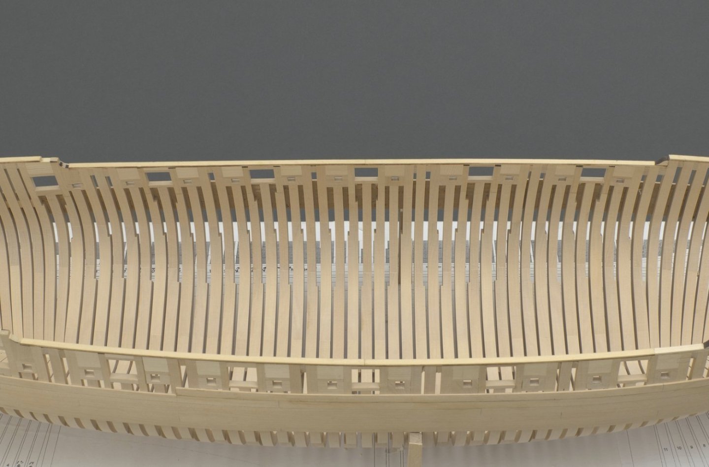
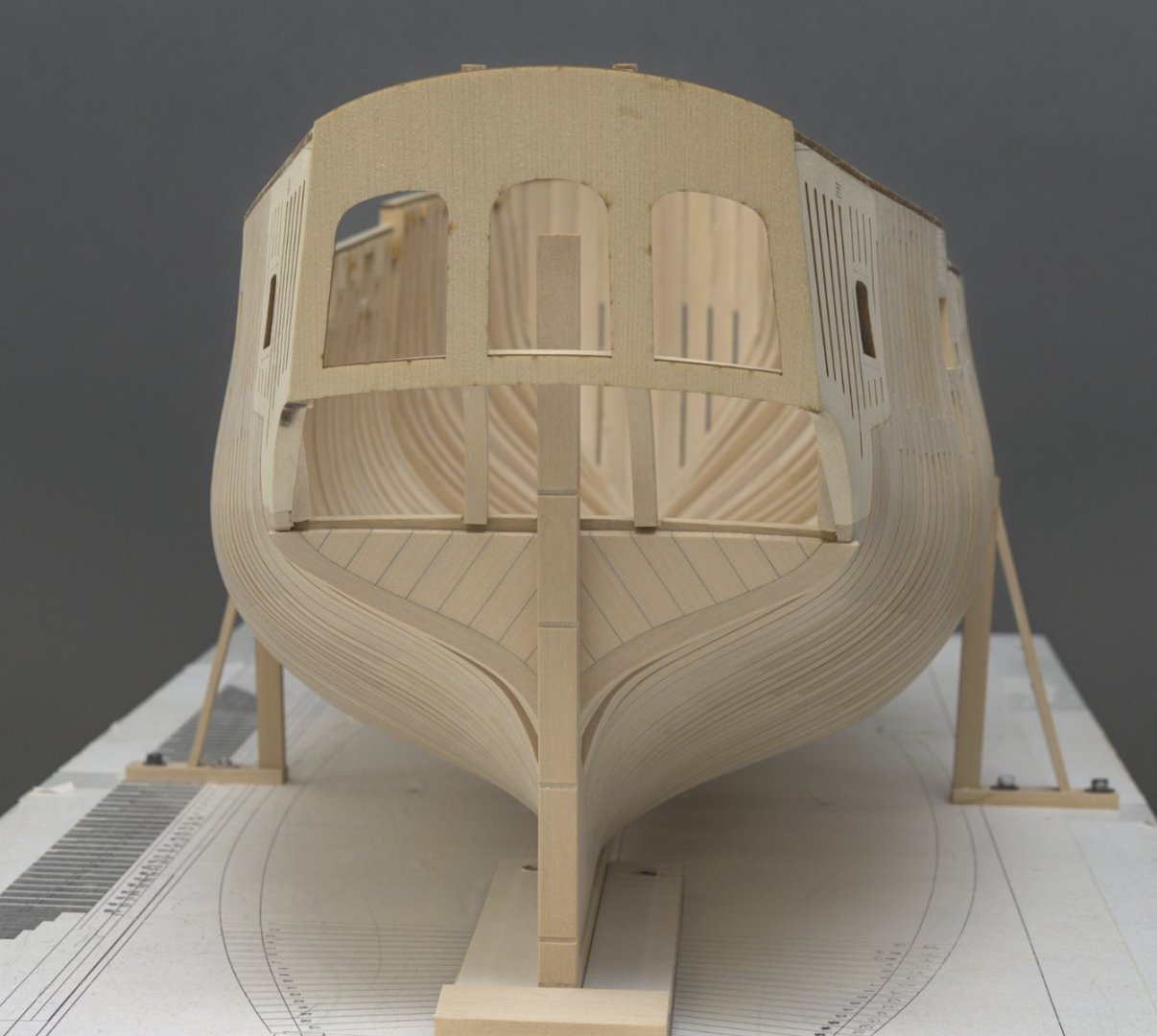
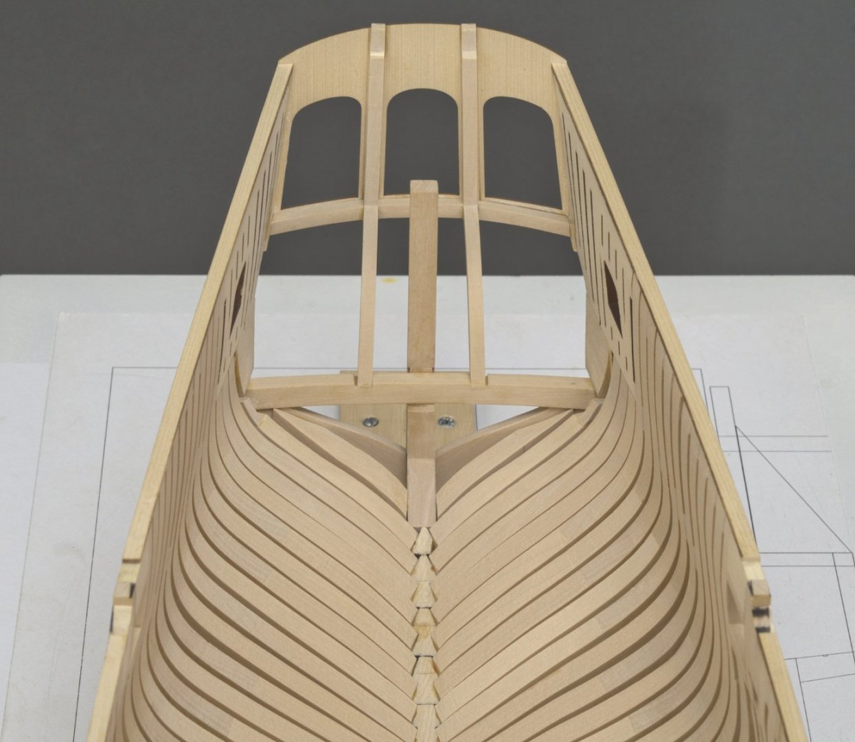
As you know, Chuck faired the hull with the top jigs in place. After supporting the hull with some planking, he was able to remove the jigs and add the fairing caps for both shape and support. Through hands on experience he knows that this approach will work out nicely. I wasn't so sure that it would work out the same for me. I was concerned that after removing the top timber jigs, I would find myself having to fair the hull a lot more. This would be quite difficult with the planking already on the hull. With that in mind, I decided to take a different approach. I added a chock between each frame where they would be covered by planking. Adding the chocks meant that I could pull the laser cut top timber jigs (before doing any planking) while maintaining support for the frames. After adding the fairing caps, I could fair the hull more accurately at the shear. Generally this turned out to be true at least for me. There were some areas at the shear that needed more work, but an inch or so below the shear the fairing work was good. Yes, a few hours of extra work that turned out well in the end. Notice that there is still enough room for the .025" cap rail to sit just below the top of the transom. There was an enormous amount of work needed to fair these aft cants. It took me the better part of three days. Remember this is boxwood, not AYC. Anyway that's done now.😁 Mike
-
Well done!