Stuntflyer
-
Posts
1,198 -
Joined
-
Last visited
Content Type
Profiles
Forums
Gallery
Events
Everything posted by Stuntflyer
-
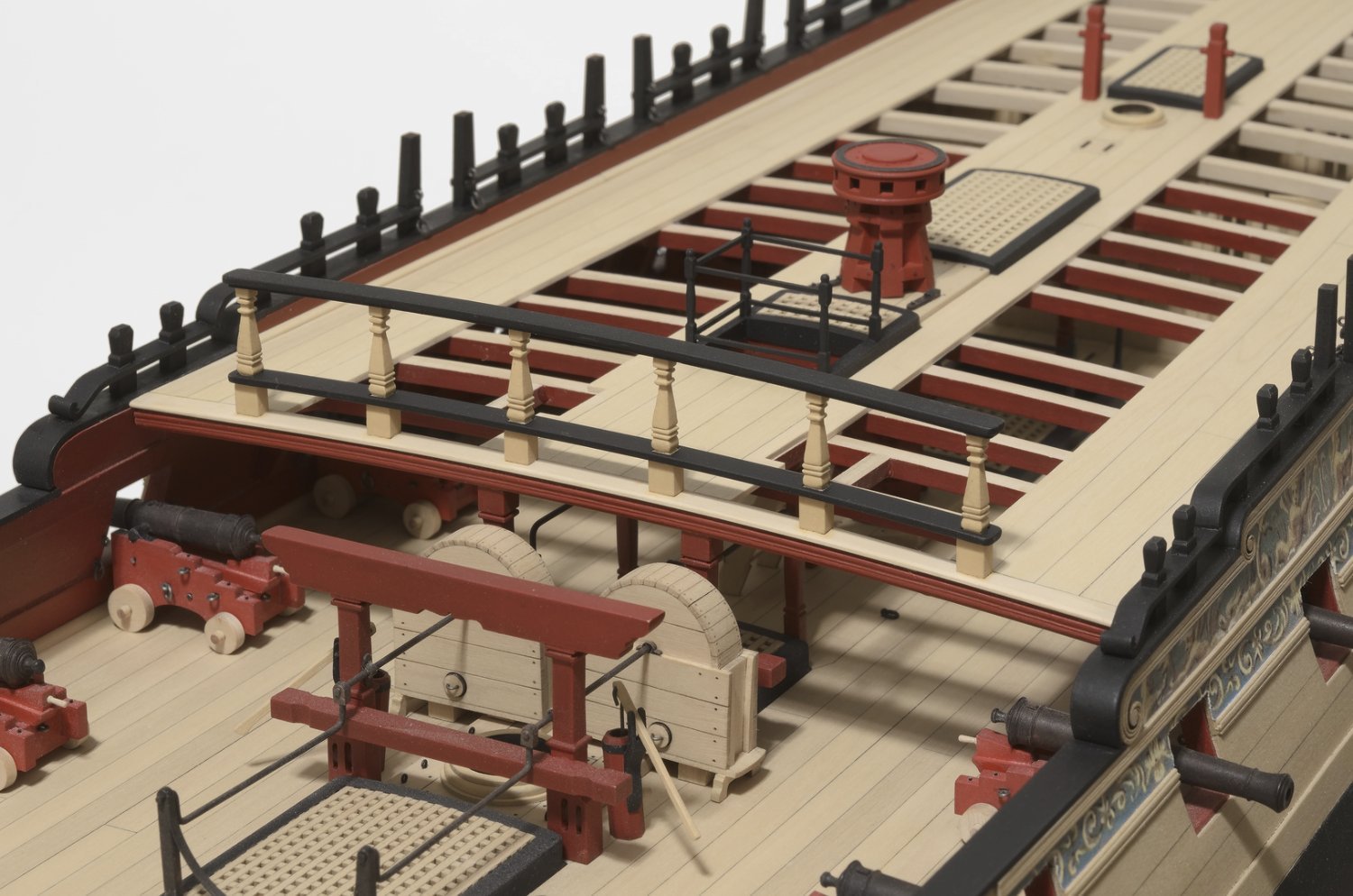
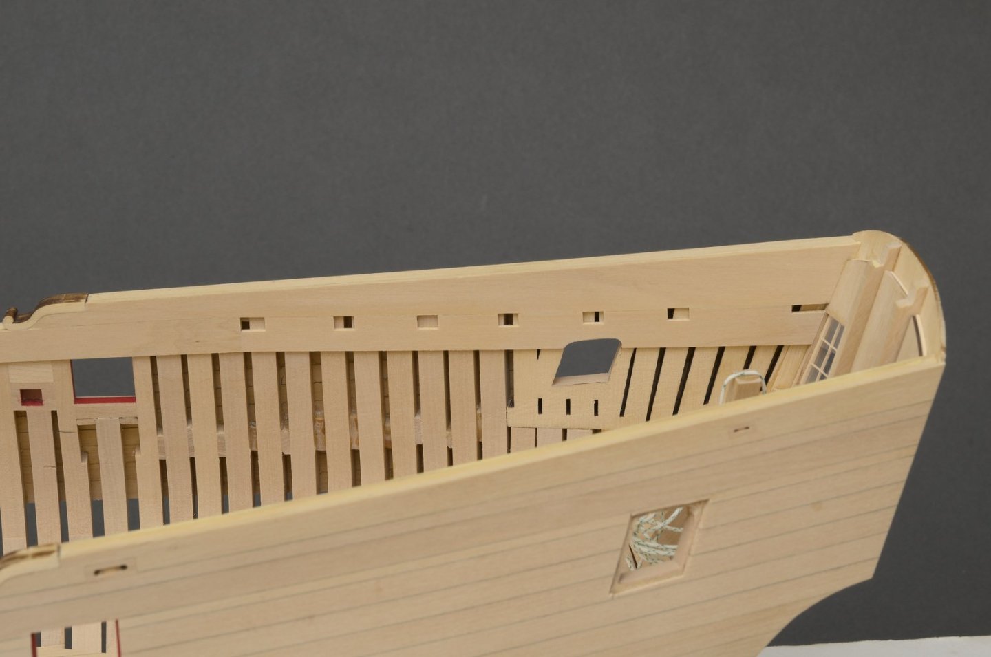
 Quarterdeck beams I finished the quarterdeck beams using the ones from Chuck. Other than having to enlarge a few bulwark cutouts, it went smoothly. I scratched the transom beam which is made in two layers. It was adjusted in thickness in order to get a smooth run of planks. To do that I made the top 1/32" thick rather than 1/16". None of the beams are glued in except for the transom beam. The deck has a curved sweep. When I push down on the plank it sits flush with all the beams. Mike

-
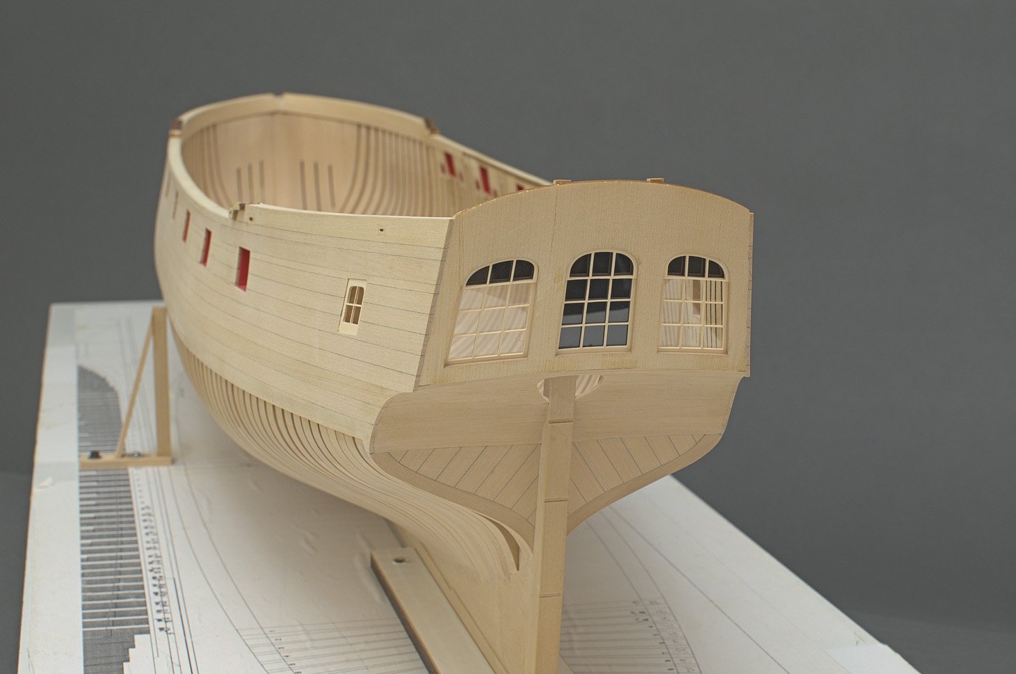
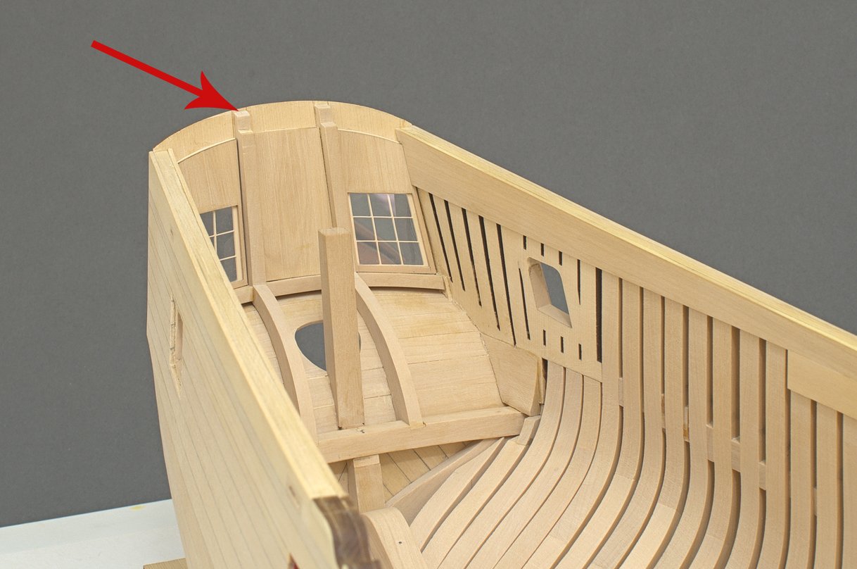
Planking the inboard sides of the cabin took more time than expected. It's wasn't as simple as just cutting tapered planks and placing them onto the hull. The curvature of the hull and twisting of the planks changes the way these all fit together. This is especially true of the lower three strakes. Some additional shaping was necessary in order to get good butt joints. I think I will paint the inside of the window framing to even out the colors a bit. Otherwise, I think I'm good to go. Mike

-
It's what I used on my breastrail columns. It won't remove all of the char, but it does lighten it a lot. https://modelshipworld.com/uploads/monthly_2022_04/Winchelsea_0307.jpg.aa662ef15d9a1ee626312ecf2e6de5aa.jpg I added some thinned wood colored paint and W-O-P afterwards for a final cleanup. Mike

- 399 replies
-
- 4
-

-
- winchelsea
- Syren Ship Model Company
- (and 1 more)
-
The great cabin planking I started with the deck clamps. I made them identical by sandwiching two wide 3/64" strips together and then milling the notches. There is some tapering needed where the clamp meets the window which changes the length slightly. So, once the first one was installed I was able to measure off of that one in order to insure that the second one mirrored it. The bottom of the aft most notch is slightly higher than the top of the window. Mike
-
Those look really nice. Have you ever tried using Gojo with a toothbrush?
- 399 replies
-
- 1
-
-
- winchelsea
- Syren Ship Model Company
- (and 1 more)
-
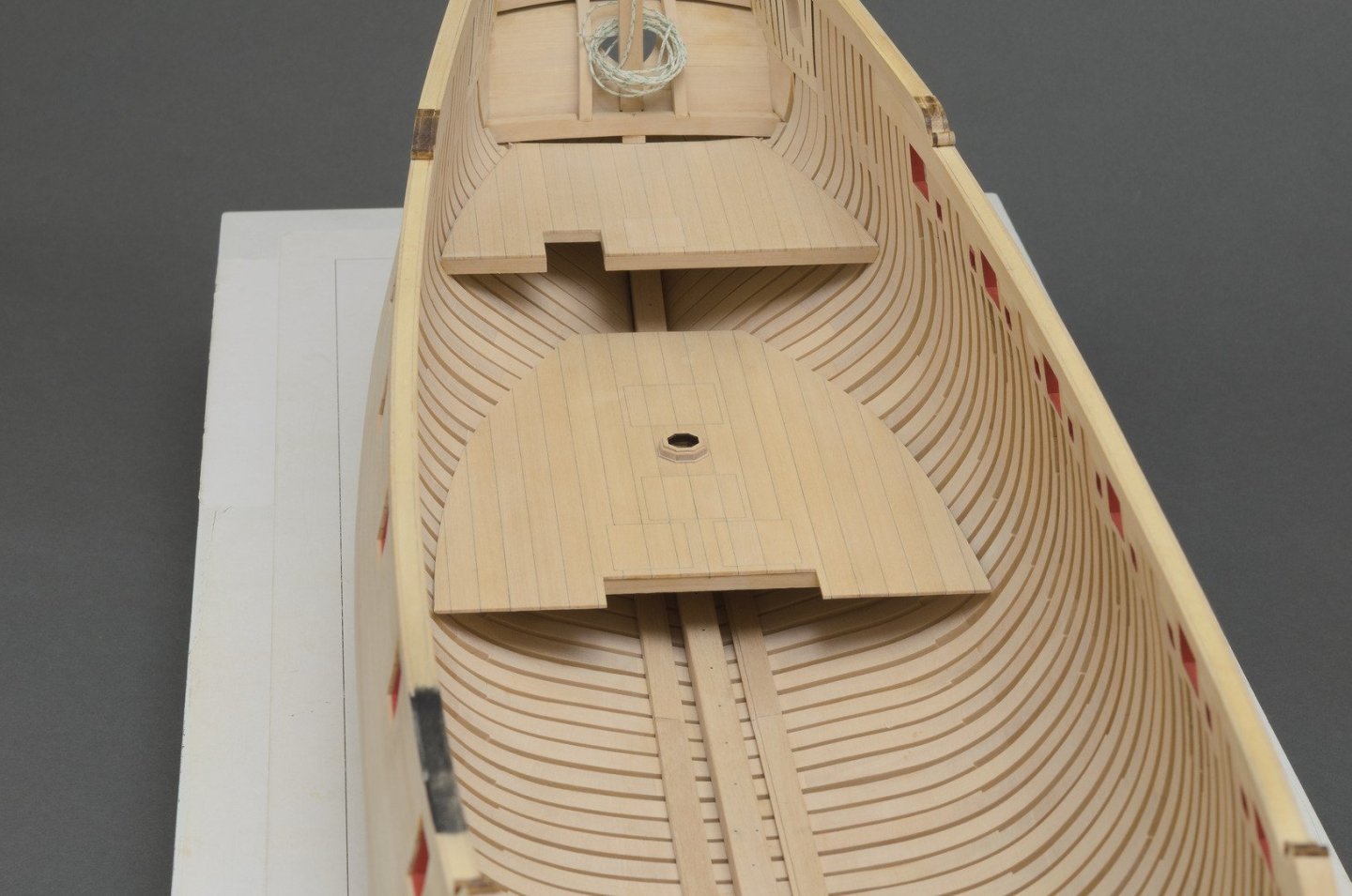
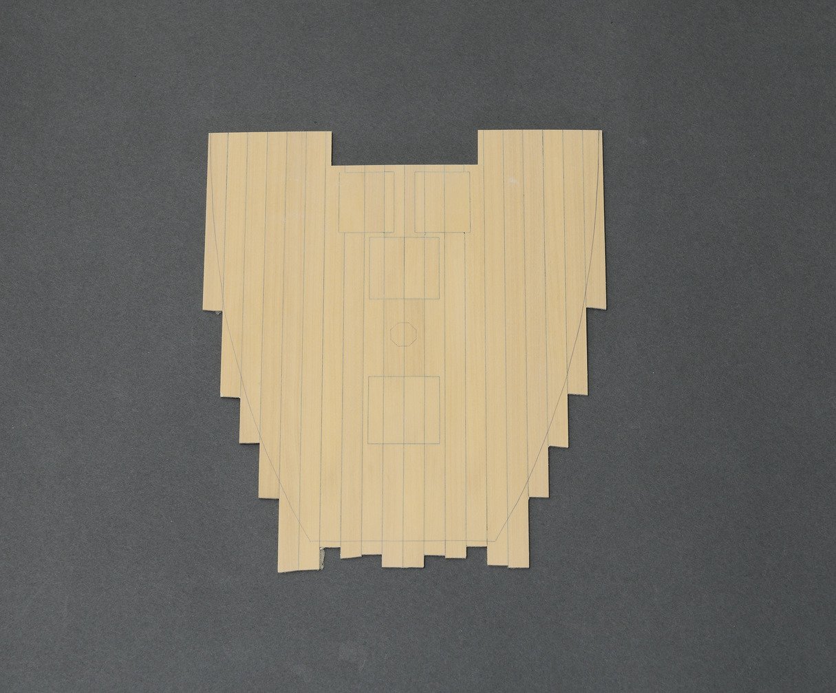
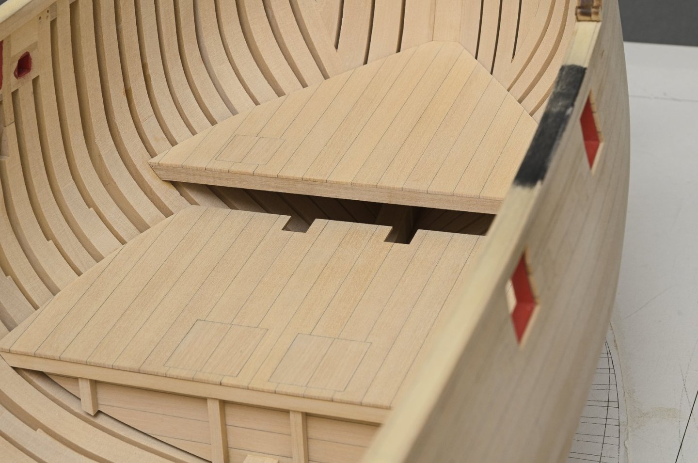
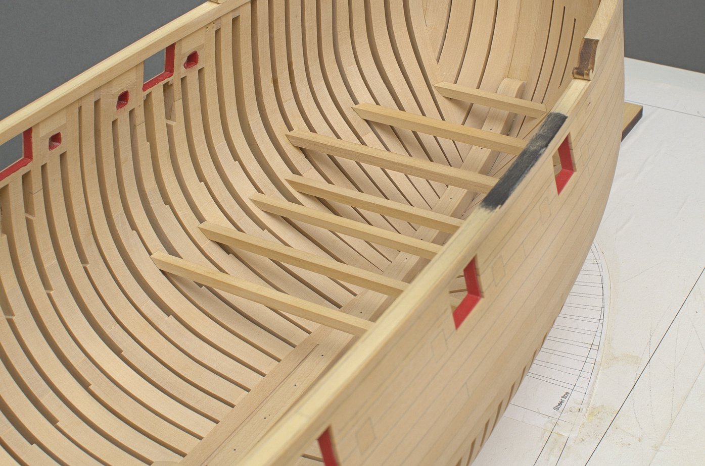
Lower platforms (aft) I've been held up a bit in getting these completed due to some mohs surgery on my neck and face. Thankfully, the doctors got it all and it's healing quickly. I did these platforms the same way as the fore platforms. The angles of the beams are a bit trickier, especially the ones further aft. As usual I used spacers between the carlings which were removed after the carlings were glued in. All of this will be covered by the platforms, but if they showed I would definitely mortise them. Making the foremost aft platform proved to be an interesting project. This was done in sections moving from the center out. Tricky but lots of fun to make. I ended up using Chuck's laser cut mast coat rather than doing it from scratch. Just wasn't in the mood for the inevitable re-dos. Mike
-
Yup! That's what I did on the Winnie only with Rusty Red instead. Nice work!
-
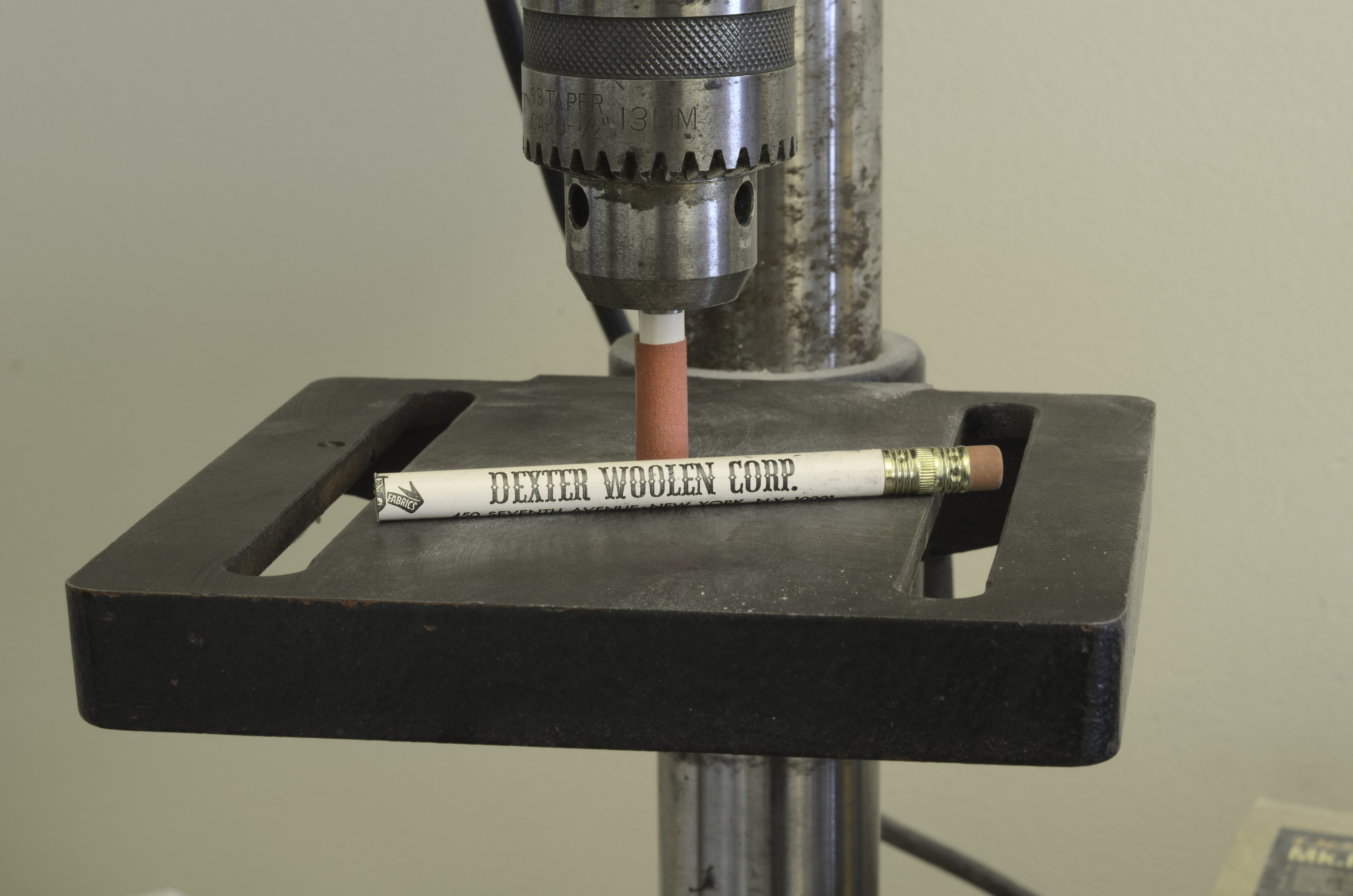
Riding bitts Making these turned out to be an interesting project. The basic shape for the pins and cross piece was taken from the plan drawings. The bevel on the ends of each piece was made by hand turning the disc sander set at 45°. Instead of using a file to shape the thin step beyond the bevel I simply added 1/64" caps made from strip wood. To shape the round offs for these pieces I wrapped some 180 grit sticky backed sandpaper around a pencil which was then turned in the drill press for shaping. Mike


-
One gorgeous ship, Mark! Can you tell me what name of the poly is? Thanks, Mike
-
Hamilton, thank you for the compliment! I think the most important thing you can do in order to build a clean ship is to work slowly and methodically. Use the right tools and treat each part as a project in itself. Do-overs are part of the hobby and there is so much to learn when doing them. So, don't settle for mediocrity. Try to get neat and tight fits when adding parts to the ship. Keep the work surface and hands clean. Think about how you want to approach each project before you start and you will get a much better result. Mike
-
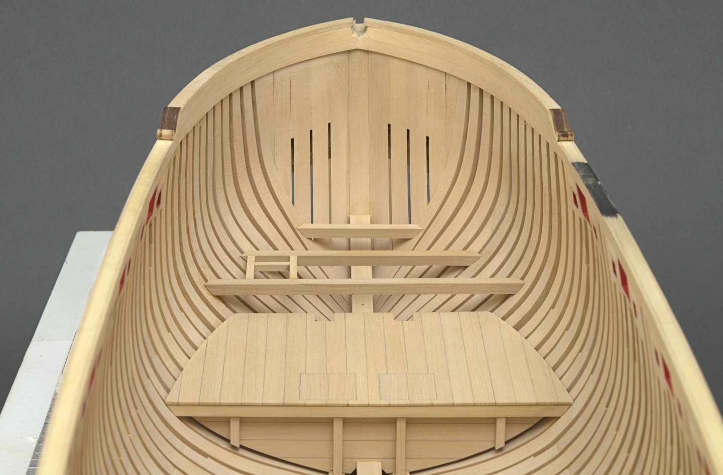
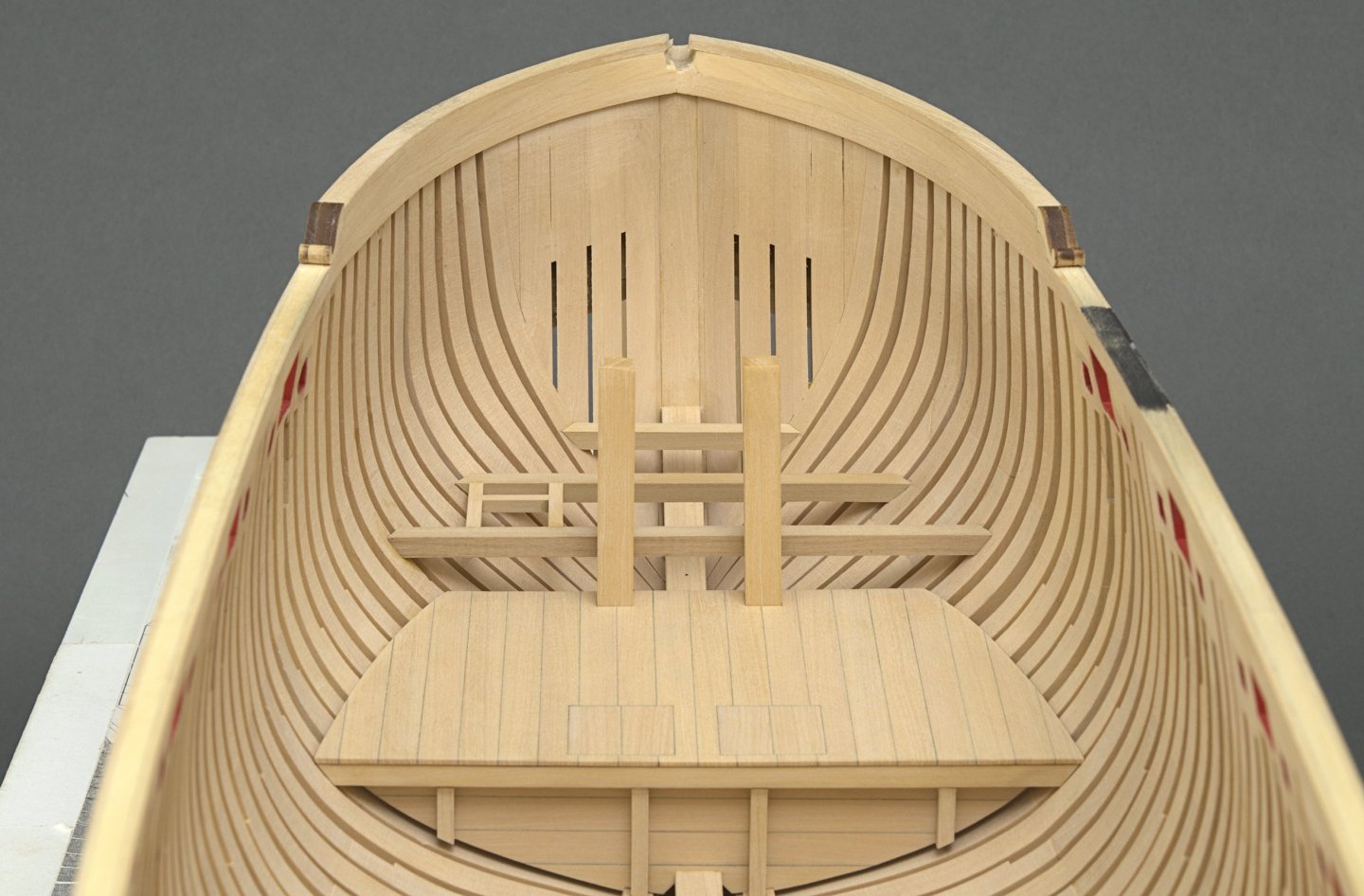
So, the riding bitts are on hold while I wait for the delivery of a 1/2" half round needle file. Meanwhile. . Breast hooks I decided to make each one these in one piece. Most of the work was done with the disc sander. Being able to set the angle for the outer edges of the hooks was a real time saver. I always try to use whatever helping hands I can when gluing parts in place. Here I used two short 7/32" strips as spacers between the deck and lower edge of the hook. Then I added a 5/8" balsa spacer which helped tremendously when positioning the middle hook. Some blue tape was added to show where the glue area will be. Mike


-
Just wanted to get this small update in before starting on the riding bitts. The lower fore decks are now completed. Mike
-
Nice, Glenn! Just goes to show what can be done with a Syren kit when it's done right. Mike
- 840 replies
-
- 2
-
-
- winchelsea
- Syren Ship Model Company
- (and 1 more)
-
Thanks! Greg>The thing is, it's so easy to not think far enough ahead. I think that we should all take time to at least try and think things through. Not only scratch builders, but kit builders as well. Rusty> That was kind of you to say. Envious is exactly how I feel when I see Chuck's Speedwell, really!.
-
Looking really nice!
-
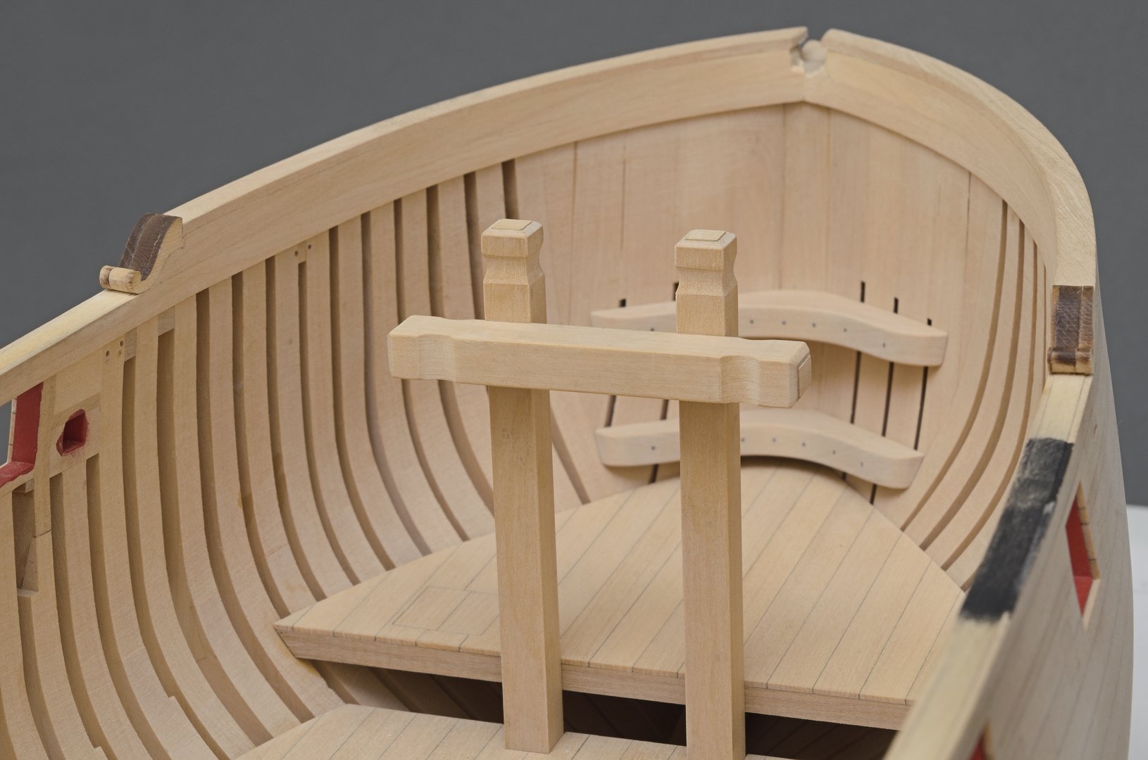
It took me a few days, but I managed to get the lower deck installed. The deck was assembled off the ship. When adding planks there was a tendency for the edge to curve slightly. That required some additional sanding before the next plank could be added. Due to the slight overall narrowing in width I ended up adding an extra plank to each side. These simulated riding bitt pins give an idea of the fit. According to the plan, when viewed from the side, the angle should be perpendicular to the keel. I used much taller pins in order to check the angle with a machinist square. The pins were leaning aft which meant that the forward most deck beam was too far forward or the one in front of it was sitting too far aft. I ended up shifting the forward most deck beam back, just over 1/64". Mike
-
Thanks, Brian!
-
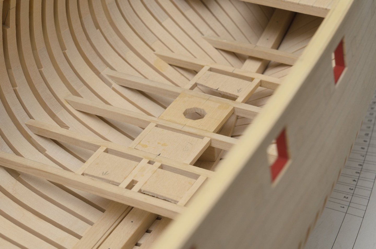
With the beams in place I went ahead and made the bulkhead for the lower platform. I ripped some 3/64" x 5/16" strip for the planks and 1/8" square strips for the vertical support beams. I used a cardboard template in order to get the approximate shape needed for the outer edge of the bulkhead. Then I added the carlings and ledges for the scuttle lids. I prefer to assemble these off the ship if at all possible. Then it's just a matter of shortening the length of the carlings to fit between the beams. Also, the ends of the carlings were angled slightly to match the angle of the deck. As you can see in the fore most scuttle lid, I used an extra ledge just to aid in squaring the parts. I will remove it later. Mike
-
Thanks, guys!
-
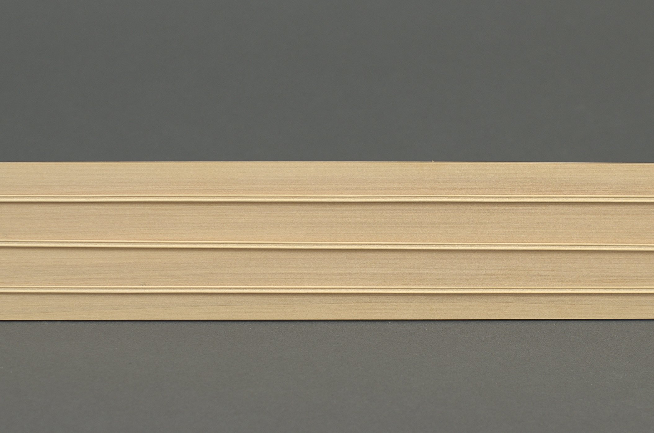
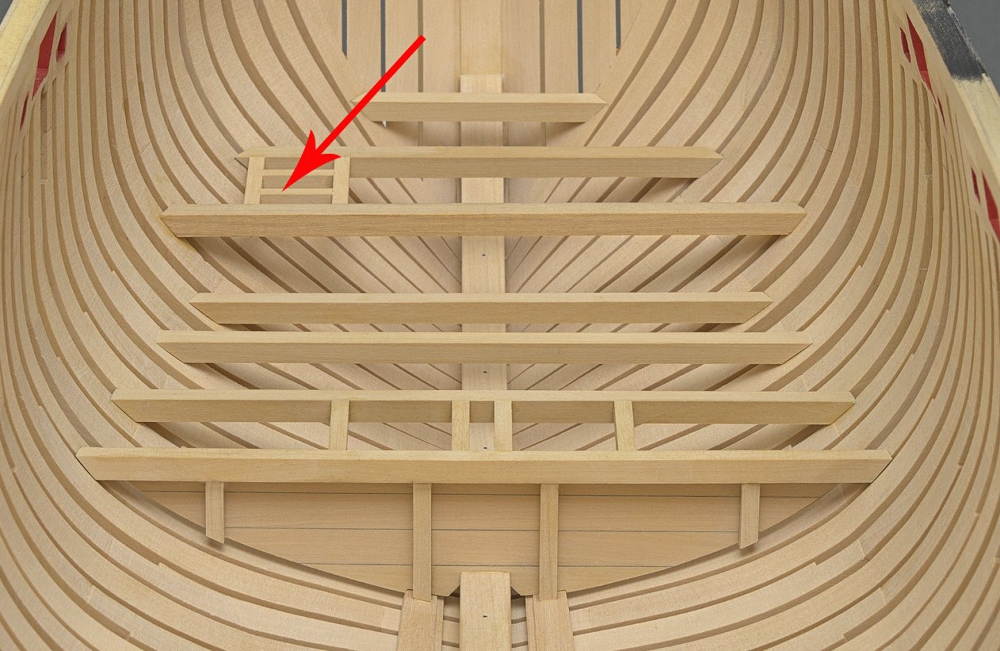
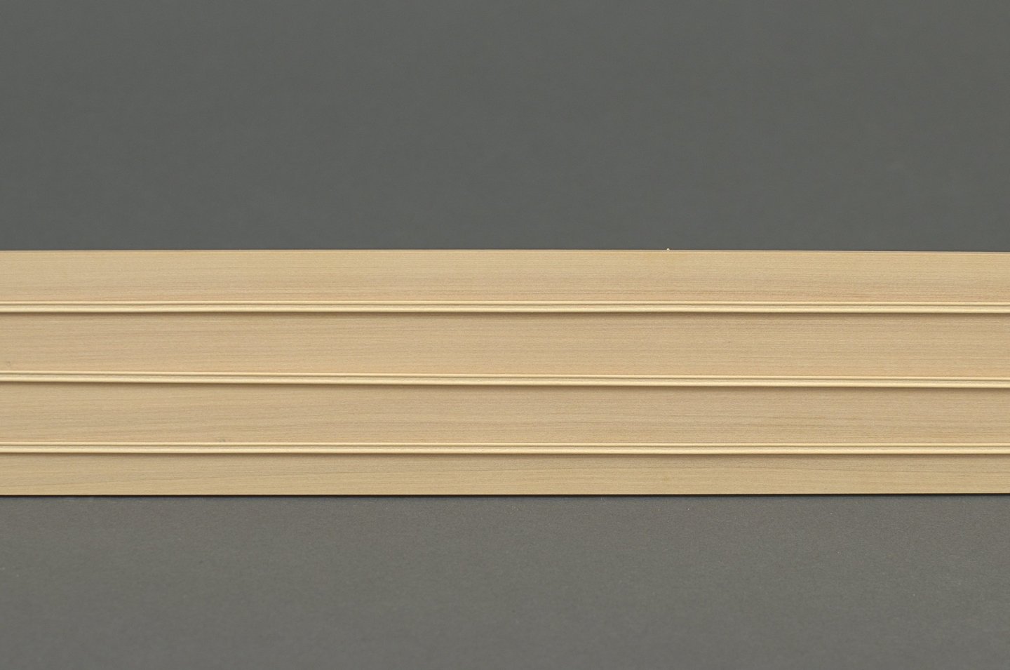
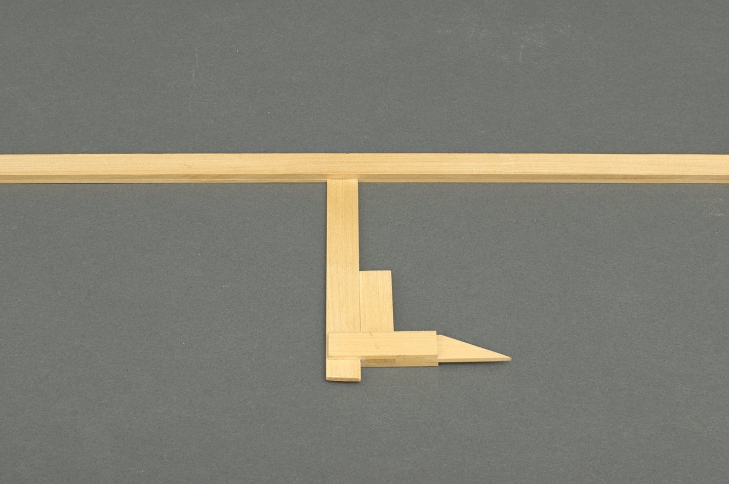
I've been working on a number of things lately. . The two inner stern frames where in need of some shortening as they were well above the top edge of the transom. I used a fine saw to make the cuts. I believe it's called a JLC razor Saw. Then I added the 3/32" cap rail to the bow section. Actually, these were taken down with the thickness sander slightly thinner than 3/32". I did this so the top edge of the scroll molding would align with the cap rail in a smooth contour along the shear. Then I scraped the 1/32" x 3/32" fancy molding for the outer hull. I went with a simple shape here. Lower platforms (fore) I went with Chuck's design for the Gauge which is needed when setting the depth of the beams inside the hull. What can I say other than it was easy to make and it worked perfectly. The disc sander really comes in handy when making these beams, especially since they are boxwood. To establish the angles for each beam, I used a slightly shorter one than needed from scrap wood. Being shorter, I could hold it against one side of the hull and approximate the angles needed. Adjustments were made to the disc sander until I was sure that the final beam would work. For the most part things went smoothly with only a few throwaways. keep in mind that the beams should not only sit nicely against the frames, but also the tops should lay flat to one another for the planking. Mike

-
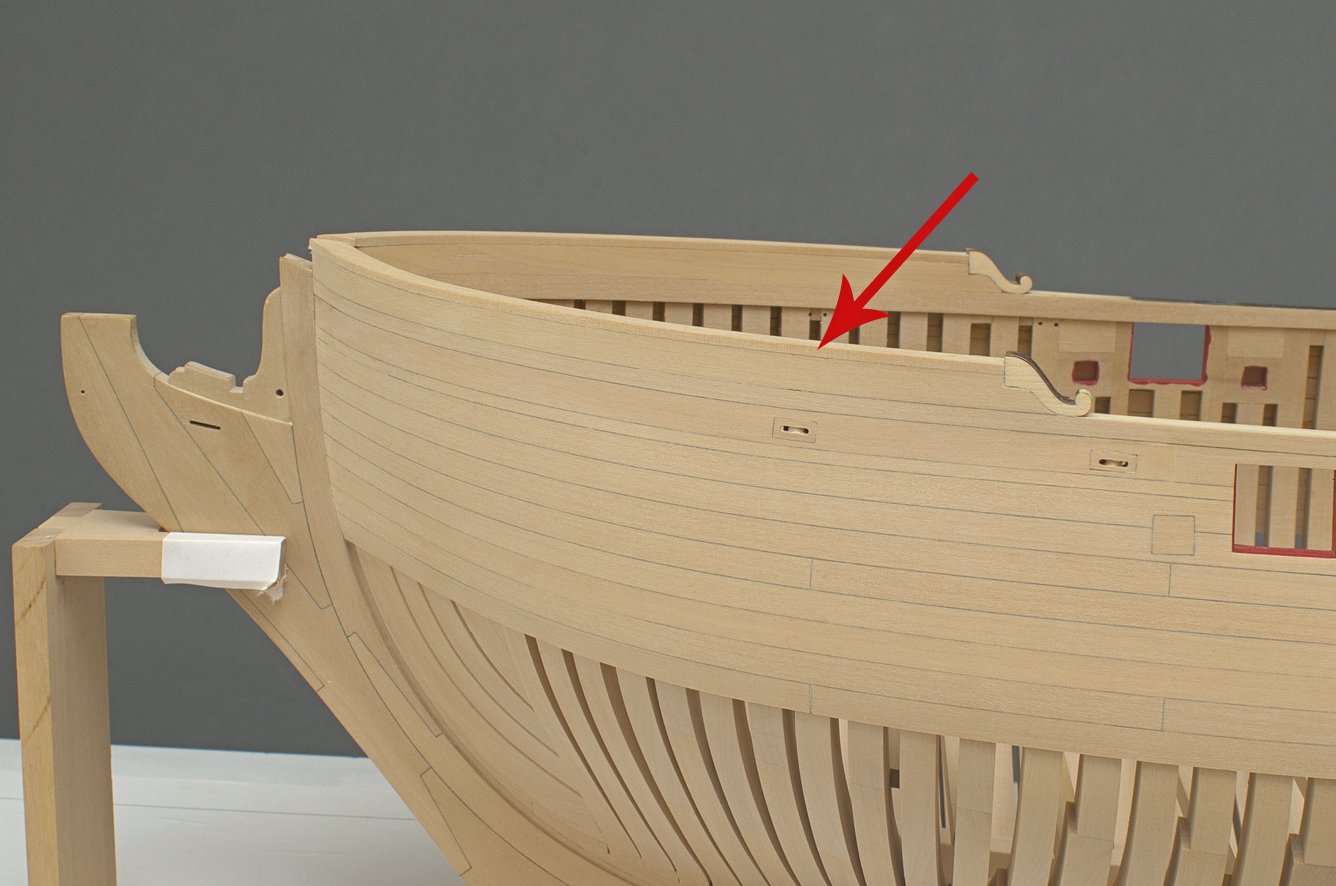
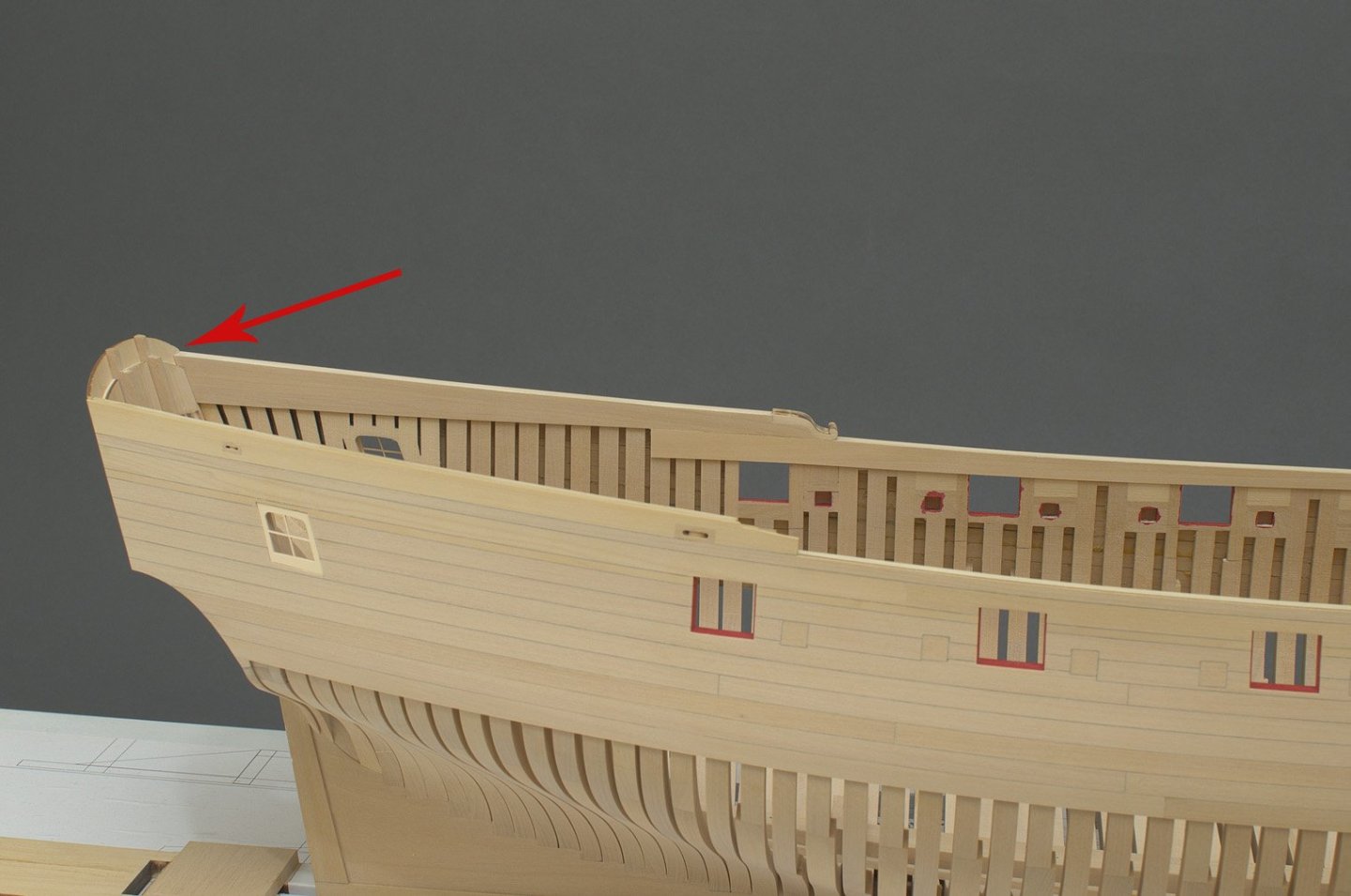
I had to add the two outer stern lights before doing anymore work on the upper bulwark strakes. They are much stronger than the laser cut wooden ones that were on the Winnie. Before installing them I wanted to remove the char color from the inside edges of transom template. Sanding was not an option, so I mixed up some paint with what seemed to be a reasonable color. Notice the reflection off the build board on the center light. I have the upper port side strakes completed. Cut from a long 3/64" sheet, I was able to combine strakes #3 and #5 together which made things easier for me when adding it to the hull. I was happy to see that the strake edge ran smoothly along the gun ports. It's hard to see, but there is a 1/64" space between the shear and the top of the transom. This allows for the cap rail to sit even with or slightly below the top of the transom, rather than above it. I planned for this in advance which might be something that you would consider doing. I sandwiched Three of those laser cut scroll pieces together rather than two which gives me more leeway as I add them to the hull. Mike

-
An 1/8" 2-flute end mill for plastics will do the job nicely. I have a source if you don't already have one. Support the outside of the cut with a piece of scrap wood to prevent splintering as the mill exits the work. Which side gets supported depends on the rotation of the mill as it exits the work.
-
Thanks, Rusty!