Stuntflyer
-
Posts
1,198 -
Joined
-
Last visited
Content Type
Profiles
Forums
Gallery
Events
Everything posted by Stuntflyer
-
 Thanks, Ken! It's always nice to hear that.
 -
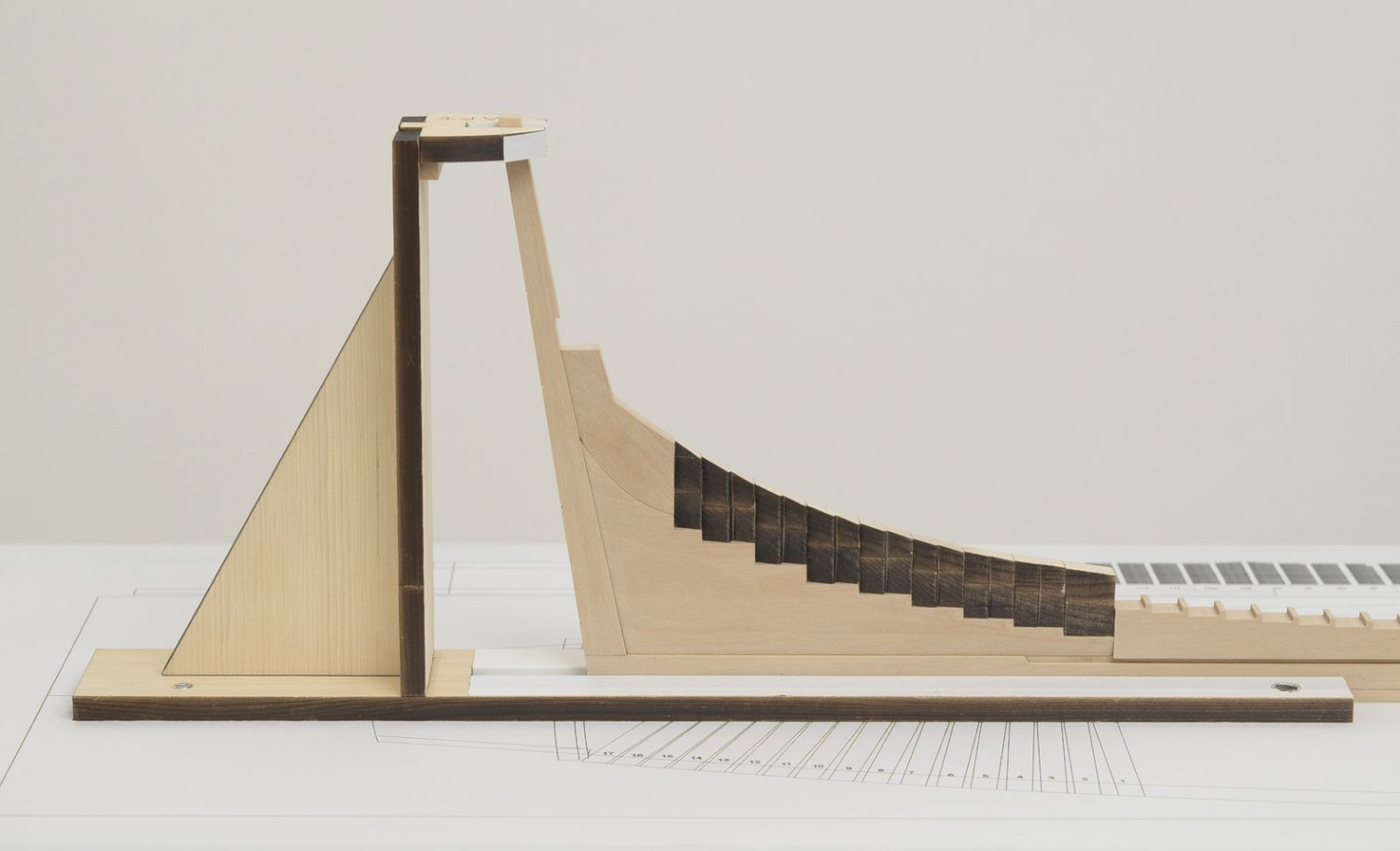
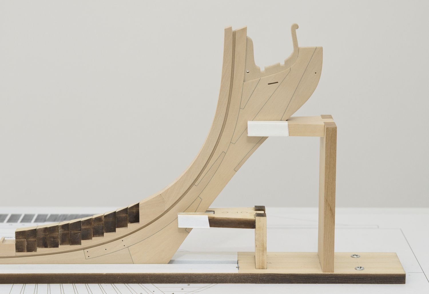
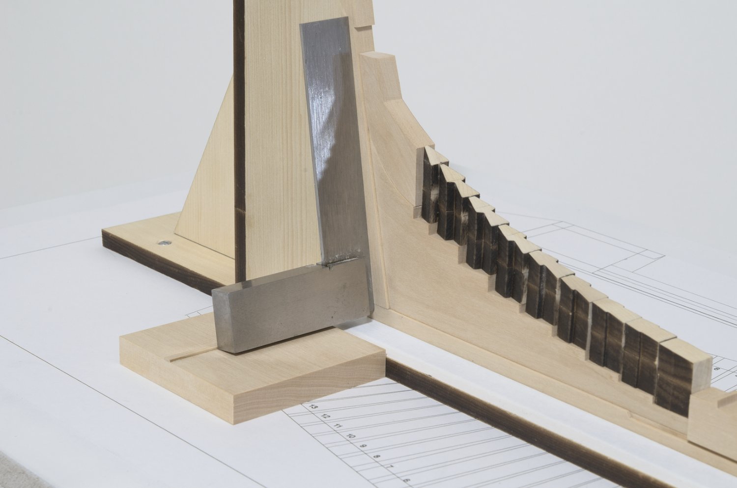
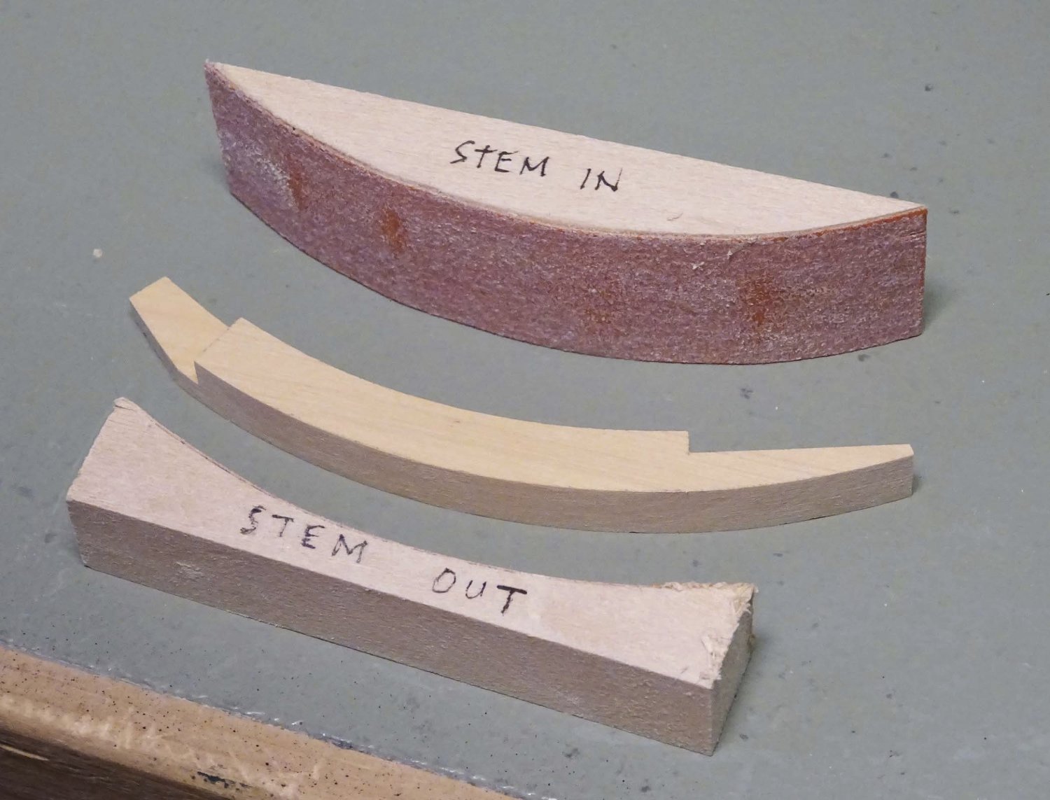
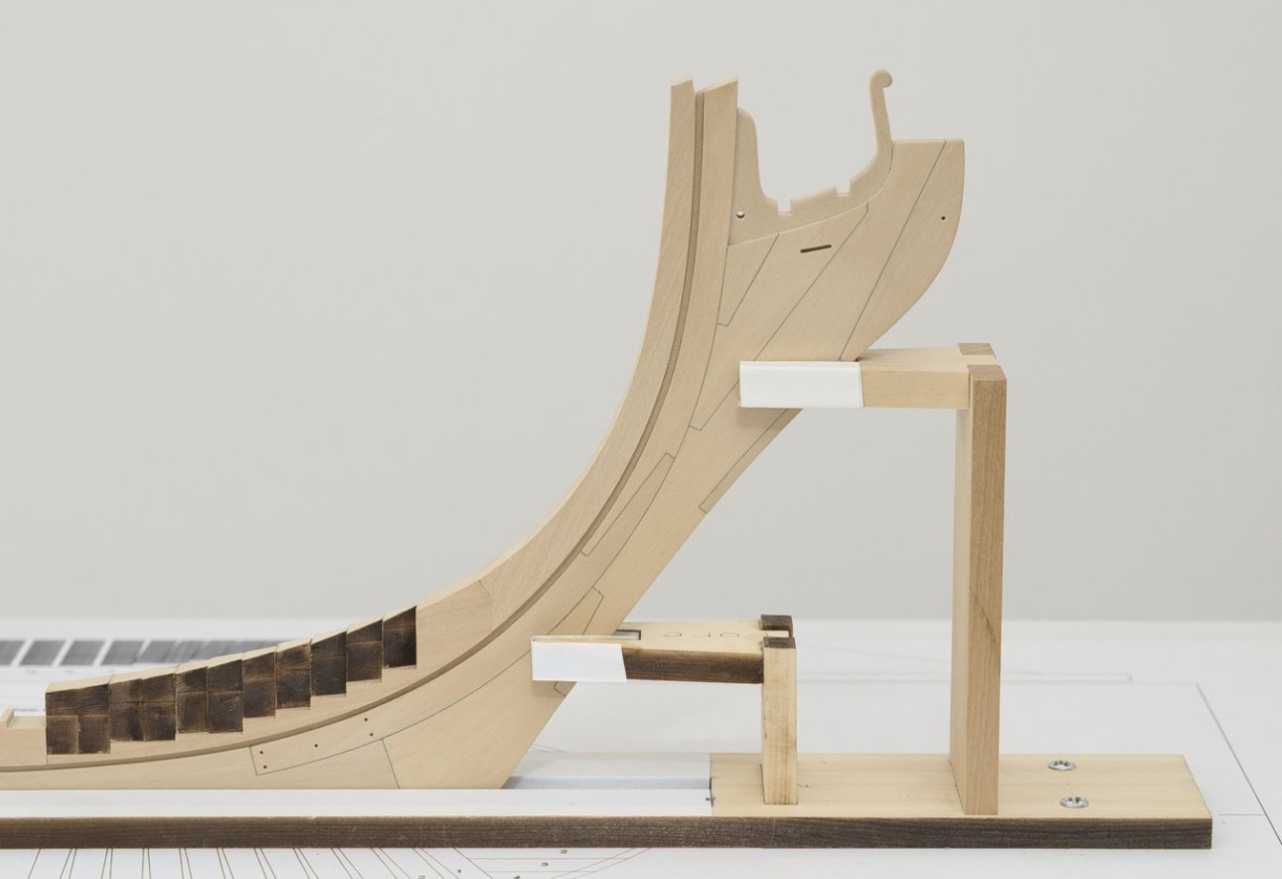
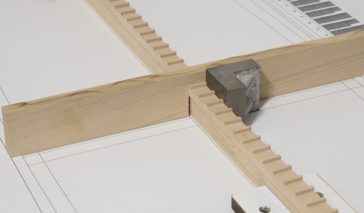
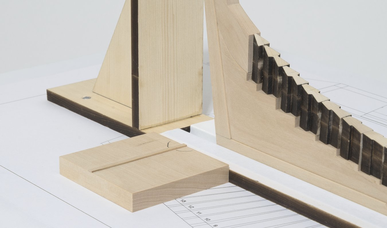
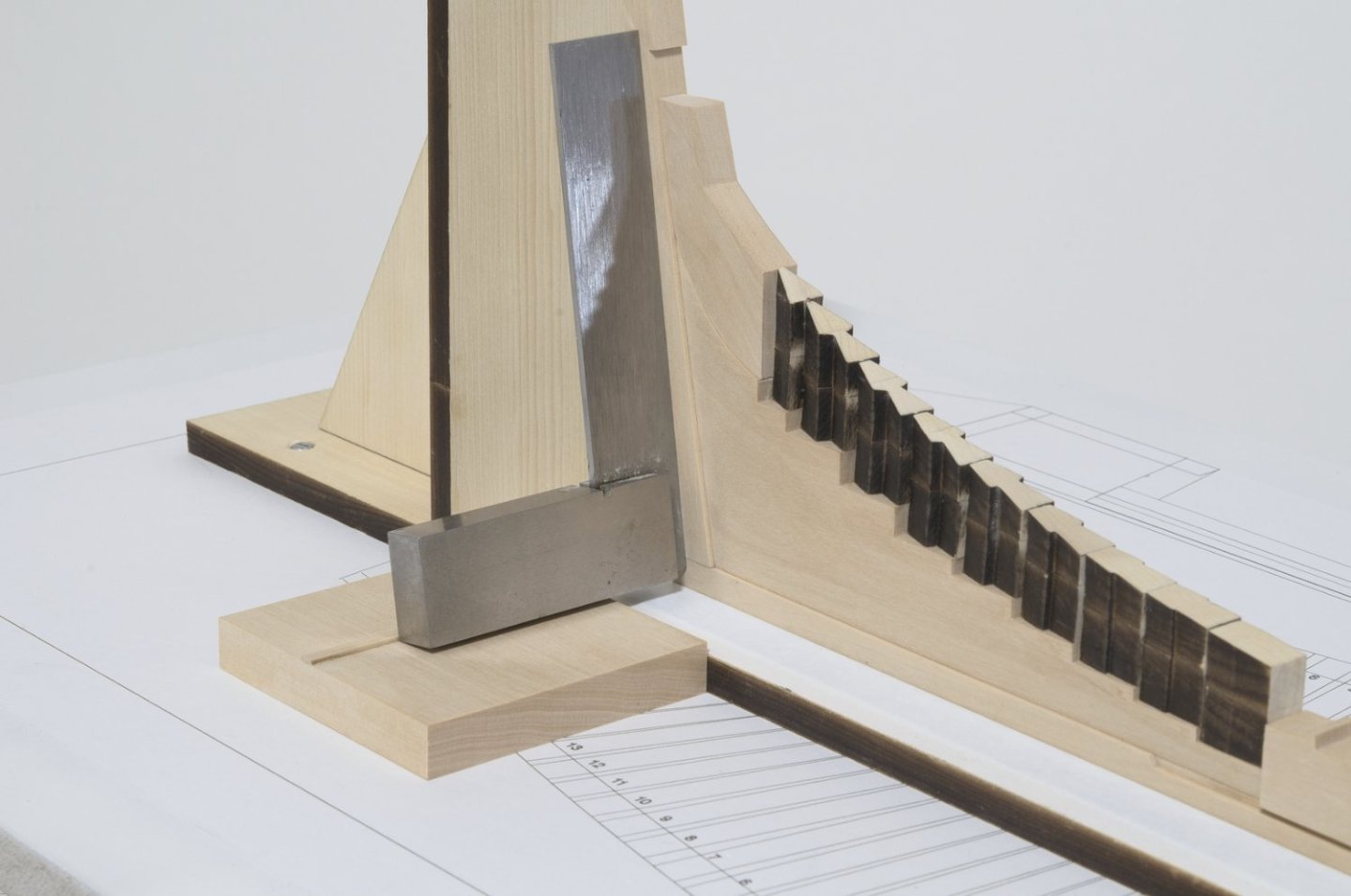
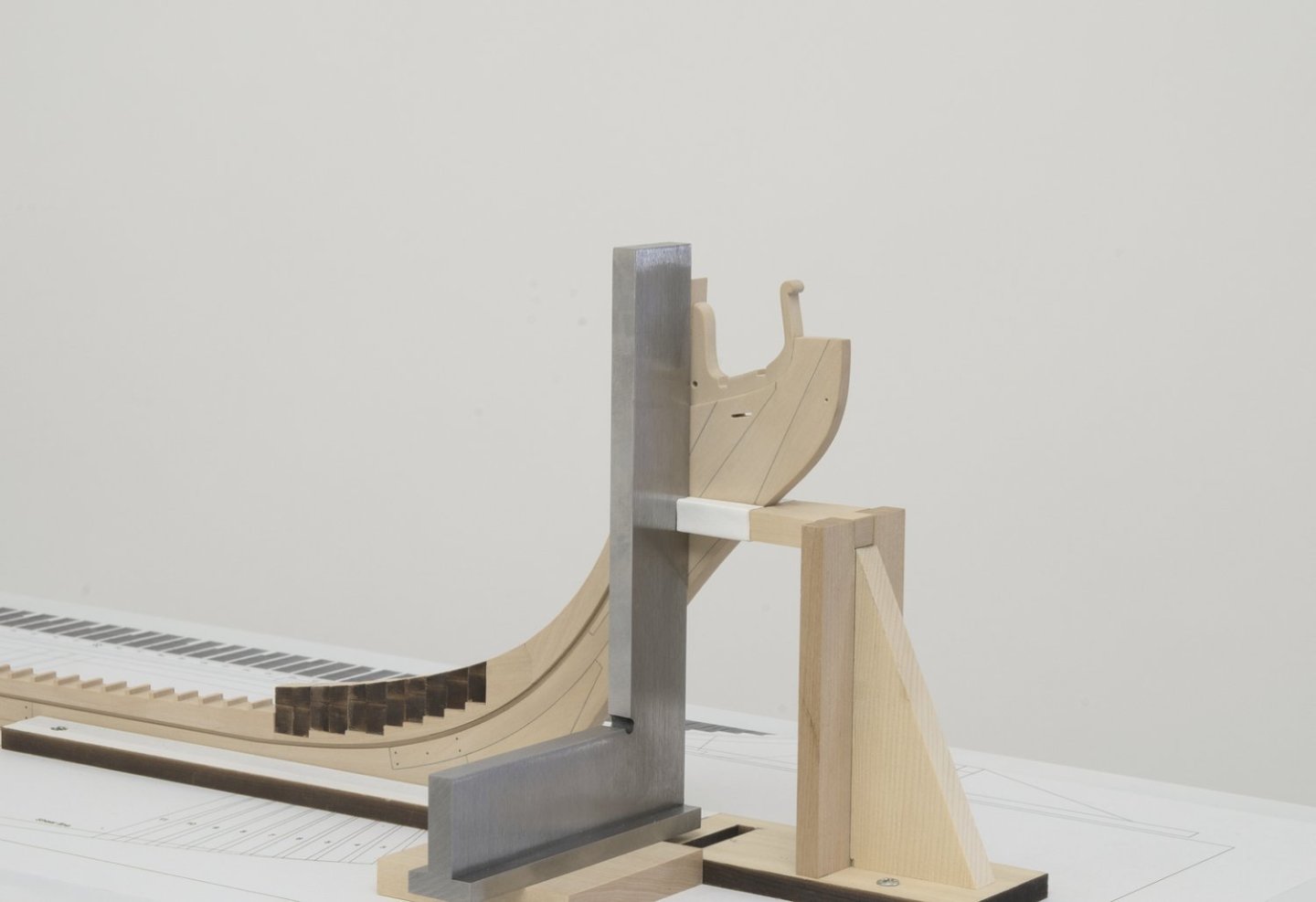
Build board (pt. 2 ) The aft keel and stern post support jig was completed first. To narrow the gap, I added about three layers of tape until the inside dimension at the closed end of the slot was about equal to that of the keels width. I used blue painters tape, followed by a final layer of white Ph neutral artist tape. https://www.dickblick.com/items/blick-masking-tape-acid-free-natural-1-x-60-yds/ I did this to prevent any chance of the blue color eventually rubbing off onto the keel. The keel was then slid into the slot in the jigs base. I clamped the open end of the slot against the keel which held everything together while aligning. After everything was aligned on the drawing, I drilled the holes in the jigs base for the bolts that would hold it down. The bolt size doesn't really matter though the holes were drilled larger into the build board allowing for some shifting of the base sideways, if needed. The upright for the stern post was added after the jig was locked down. I added some tape here as well in order to close the gap in the slot. The upright has a laser cut tab that fits into a wider slot in the base. This allows for the upright to be shifted sideways in order to get the stern post vertical. I made a jig in order to position a machinist square 90° to the keel while leaning it back against the stern post. The forward keel and knee support jig was done basically the same way as the aft one with one small change. I went with a custom made taller knee support. I felt that it held it more firmly and made it easier to set the stem vertical. I can always remove it later if necessary should it get in the way of things. Here is photo for comparison showing the lower and upper support. A machinist square was placed against the stem, not the stemson, as a means for getting the knee vertical. After the fore and aft jigs were completed, I made a simple jig in order to see if the keel was square to the drawing. You can just make out the line close to the base of the jig. Mike

-
Only you can make that decision, Steve. Do-overs are common in this hobby. Believe me, I know! Mike
-
Looking really nice, Rusty! Your almost ready for the fun part.
- 642 replies
-
- 2
-

-
- winchelsea
- Syren Ship Model Company
- (and 1 more)
-
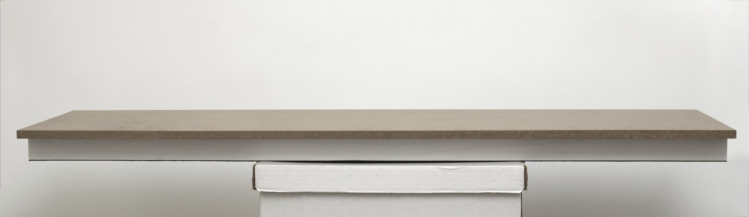
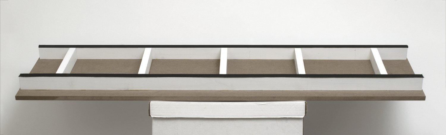
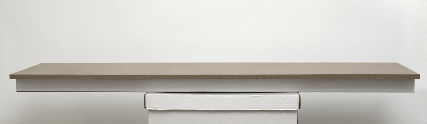
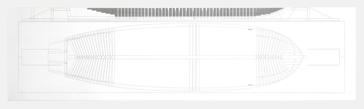
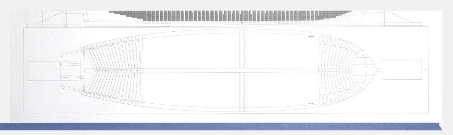
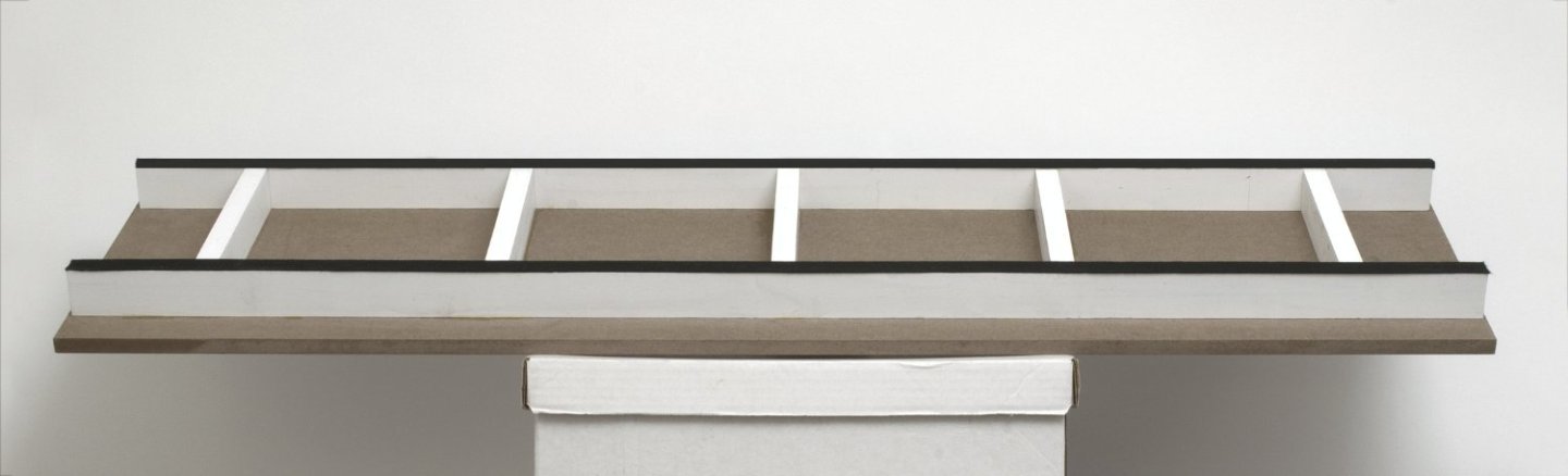
Build board (pt.1) The boards platform was made from a sheet of 1/2" MDF cut to 12”x 42". For support I added primed 3/4”x 1 1/2” strips underneath. All of the strips where shaved on the table saw in order to establish a straight edge when gluing them to the board. The shorter cross strips were shaved slightly deeper than the two long ones in order to recess them. Clamps were used to hold everything in place while the glue dried overnight. 3/4" Polyester Felt Tape was added to the two long strips to allow for sliding the board on the work table. https://www.amazon.com/dp/B01455QMX4?psc=1&ref=ppx_yo2ov_dt_b_product_details I primed the MDF with a few coats of Krylon colormaxx white primer. https://www.amazon.com/Krylon-K05584007-COLORmaxx-Spray-Aerosol/dp/B07LFWPFLC The primer was then lightly sanded smooth with a flat sanding block and some 400 grit sandpaper. The build board was now ready for the plan sheet. I trimmed the plan to a desired dimension, leaving a view of the lower frames on the sheet as a reference. To protect the printed lines I sprayed on some Krylon Workable Fixatif. https://www.amazon.com/Krylon-K01306-Workable-Fixatif-11-Ounce/dp/B00023JE7U Once I established the positioning I placed some blue masking tape on the board to aid in the alignment of the sheet. I placed a centering tic mark on both the tape and plan sheet. I used Scotch Repositionable Spray Adhesive to adhere the plan to the build board. https://www.amazon.com/3M-Spray-Artists-Adhesive-MMM6065/dp/B00006IFBF My amazing wife helped me to hold this long sheet of paper while we carefully placed it on the board. Mike
-
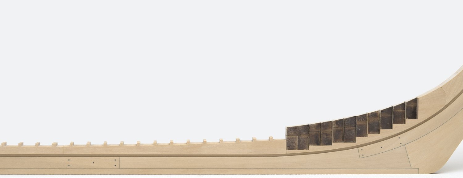
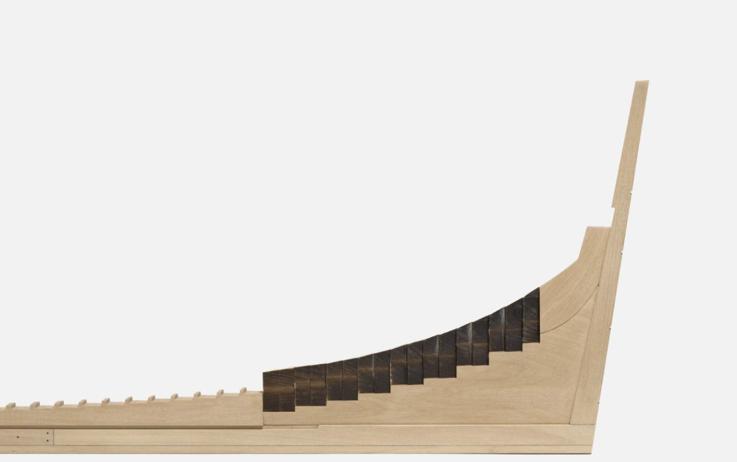
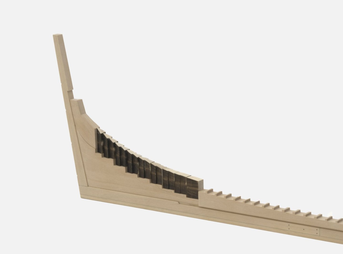
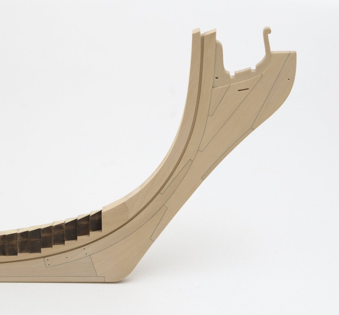
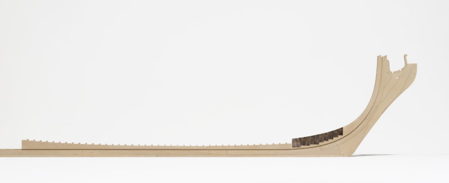
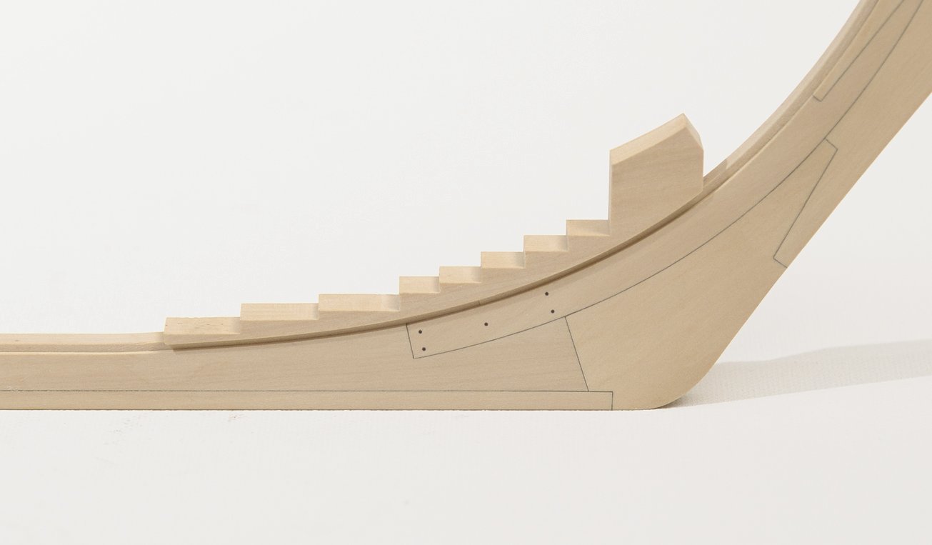
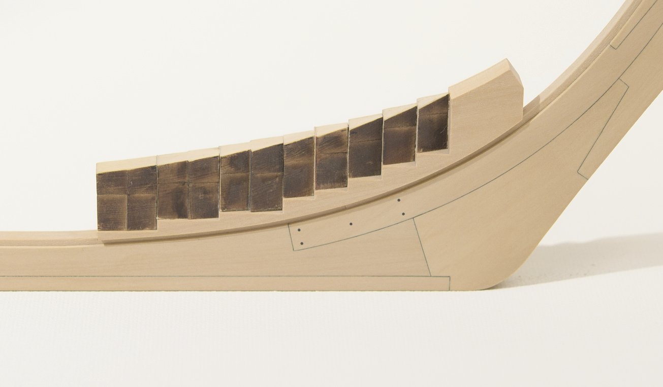
Aft deadwood, stern post, wedges With the addition of these parts, the central spine is finished. The stern post and the steps in the deadwood were cut on the mill. The straight taper in the deadwood, from the bearding line down to the foot, was done as described in Chuck's build log. There is a lot more wood to remove here than you might think. I often checked the work with a straight edge to insure that the final taper was straight and not rounded. More sanding will be needed later when it comes time to fair the cant frames. Mike
-
druxey, that’s a good point. I will keep it in mind.
-
I suppose you could, but honestly I don’t think it’s necessary. The tape should do the job of protecting the wood while it is on the build board.
-
Diver, are you sure? Looking at something unfamiliar to you might seem unattainable. This is much easier to do than the traditional way in which it is often done. Chuck has made this very straight forward with etched lines and laser cut shapes to start off with. He has simplified the process for those who want to build a POF and thought they never could. Mike
-
Mike, thank you!
-
Looking quite nice! I can see that the fourth air space isn't needed at all.
-
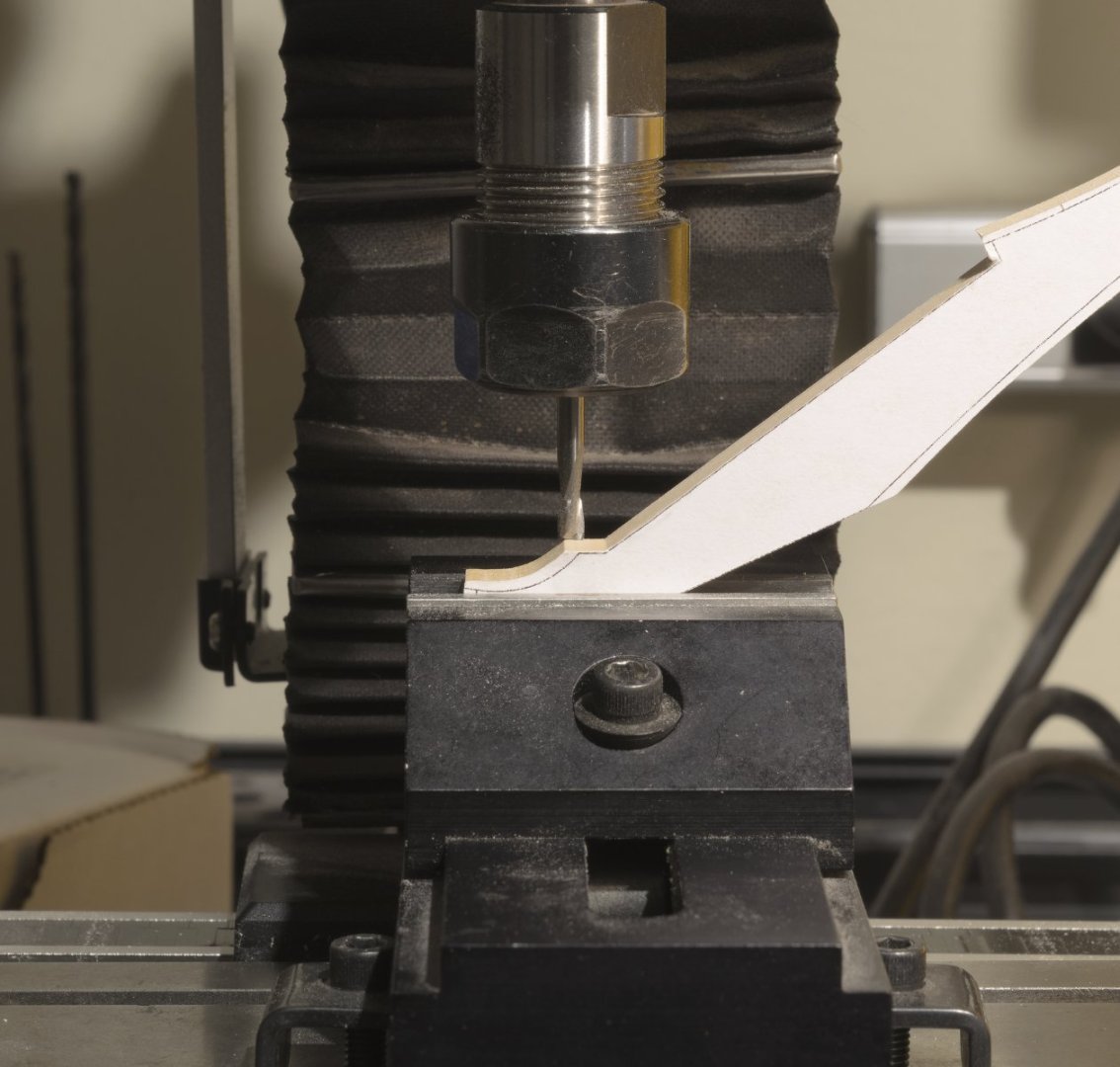
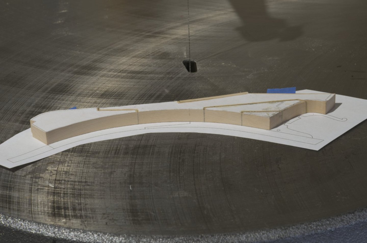
Stemson, rising wood Moving along, I added the stemson and rising wood. Shaping and adding the stemson was straight forward. After that, I started work on the rising wood. Using a piece of 3/8" boxwood, I carefully copied the dimensions of the rising wood using the new milling machine. So much fun! All of the slots are 5/16" which made the process much easier. Basically a two day process that went along quite smoothly. I just needed to stay focused and not rush through it. Mike

-
Tom, I do have DRO. Thanks for the tip on a slitting saw.
-
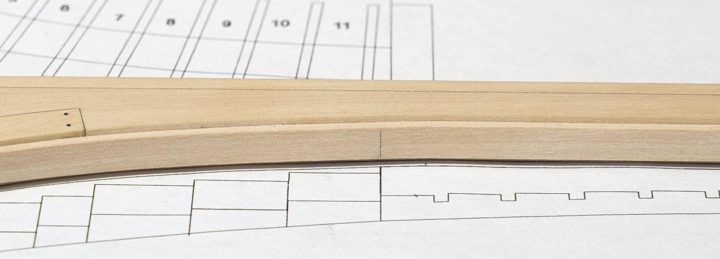
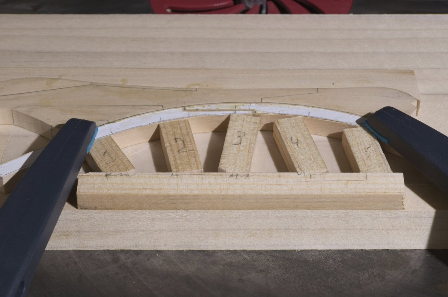
Fore deadwood In order to find the exact location, I aligned the central spine with the plan and carefully marked the aft location of the fore deadwood. Having just purchased a Sherline mill, I thought it would be a good time to try it out. With that in mind I made the fore deadwood from 3/8" boxwood. I'm pleased with the result. I added the deadwood to the keel using the registration mark I made on the keel. As I mentioned earlier, I'm going to maintain the build concept. With that in mind I went with the laser cut angle wedges for the cant frames. A mix of scratch and kit. When adding the wedges I left a little wiggle room because shifting of these pieces was necessary in order to align them fore and aft. The tops of the wedges were reduced to match the shape of the keelson before gluing them to the deadwood. Mike
-
Fred, I have often thought about showing, in great detail, how I go about making parts. The problem I always seem to run into is how to go about doing it knowing that certain subtle techniques are involved. Take the stem for example. As Greg knows, the oscillating spindle sander on curved surfaces can give a smoother result than that of a scroll saw. That gets you somewhere in the ball park. The final shape still needs to be achieved and can be further honed in with some 90° sanding blocks. For myself, I will hold the pieces against a window in daylight and look for light leakage. It can be very time consuming and the back and forth takes technique, finesse and a lot of patience. HTH. The gammoning knee was cut from an attached paper template on the scroll saw. The final shape was achieved with the disk sander, sanding sticks, #11 Xacto blade and assorted needle files. It would be very difficult for me to put that in writing in such a way that would be easily understood, I think. Mike

-
Mark, Thank you! Rusty, I can't wait to see my approach to the frames as well. I guess I'll figure it out when I get there.
-
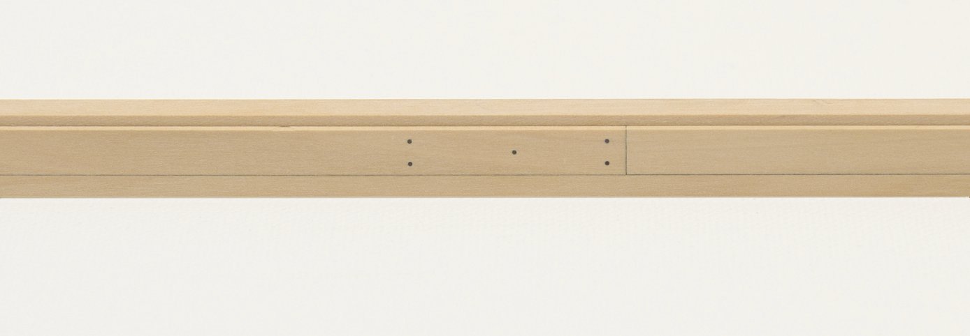
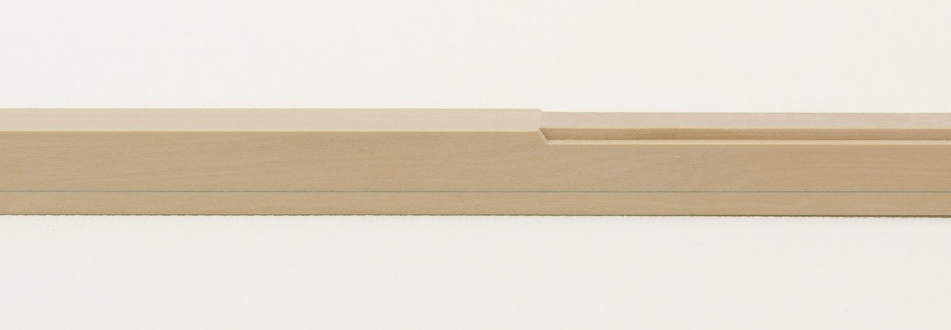
Hi Dave, Thanks for your interest. Have you considered starting a build log? It would be interesting to see a POB version. Continuing with some catch up on my progress so far. Keel This is all very similar to what I did on the Winchelsea. The lower stem has a true boxing joint. The straight lengths of keel were made from two layers of 5/32” sheet which were offset, thus creating the half lap joint. The first section I added was the one that attaches to the knee and stem assembly. Additional keel sections were added to that by working aft. The false keel and rabbet strip were then cut and added to the keel. For the keel bolts I used (.023) 30 pound black fishing line. The only change I made was to use a No. 73 bit instead of a No. 71. It provided the snug fit I was looking for. Holes were drilled about 1/8” deep. Mike

-
This always worked well for me. I wrap a paper towel around the parts and soak it with alcohol before wrapping everything with clear plastic wrap. I usually let the joined pieces sit for 4 hours before removing the wrap.
-
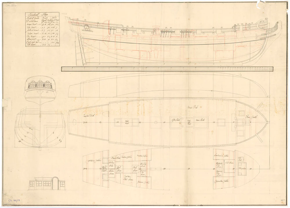
My build log for Speedwell is now ready for viewing. https://modelshipworld.com/topic/34077-sloop-speedwell-1752-by-stuntflyer-mike-ketch-rigged-sloop-pof/#comment-970081
- 607 replies
-
- 2
-
-
- winchelsea
- Syren Ship Model Company
- (and 1 more)
-
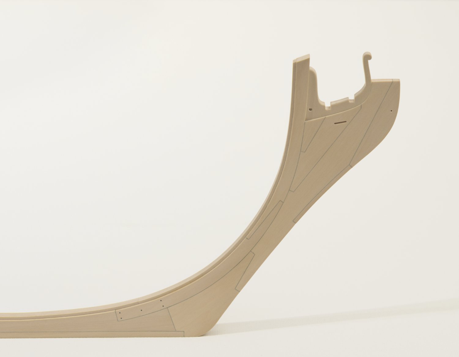
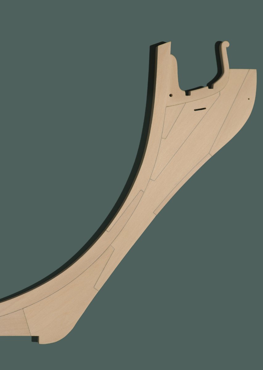
I am very excited to be starting Speedwell, my next project and build log. Over the years I have really enjoyed collaborating with Chuck while building his designs. That includes all the ships I have built which are the 18th Century Longboat, Cheerful, and most recently, Winchelsea. Without his help I would never have been able to accomplish anything near what I have done so far. As always, I come away from each build knowing that there is always room for improvement. Hopefully Speedwell will show signs of that. My first attempt at POF was David Antscherl‘s Hayling Hoy. Although it might be considered a first time POF model, I found out quickly that it had many challenges for me. The scratch frames were just one of them. Since that time I never lost interest in trying another POF. Chuck first mentioned building his version of Speedwell at 1/4". At the time, I really wasn’t all that interested in doing a small Speedwell like what Greg Herbert was already working on. That all changed when the decision was made to build an up-sized version. I was not surprised to hear that Chuck would add his own interpretation of the ship which would make it all the more interesting for me to build. Speedwell will be a mix of scratch and kit. Just how much of each I really don’t know. The plan is to build the ship in boxwood which is not an option offered by Chuck. For that I have turned to Hobbymill.EU as my source for the wood and I highly recommend them. https://www.hobbymill.eu/ If I were to go the more traditional route like Greg did on his beautifully built Speedwell, then my build would be a hybrid and I would not be able to follow Chuck on this project. The reference for the build is Chuck's build log and forthcoming monograph. I will try to mention only those things that are different or unique to my build. I think that this would be less confusing for those who wish to follow both logs. My goal is to stay scratch as much as possible while maintaining the basic procedures that Chuck would want all of the builders will follow. It will be challenging in places where it would otherwise be relatively easy. Honestly, I really do prefer it that way. Chapter one: knee of the head, stem and gammoning knee The knee of the head was made in the usual way. Individual pieces were shaped to the outline of an attached paper template. The paper templates were attached with Elmer's School Glue which I find holds better than rubber cement. The paper can be removed easily with a little water on a Q-tip or paper towel. The mill made it much easier to cut some of the straight segments in parts like the lacing piece. One more piece then ready for final outer shaping before adding the stem assembly. The stem assembly is added to the completed knee assembly. The knee sits against a backing piece and small pine blocks are used to tighten the joint while the glue sets. When sanding the flat taper in the knee of the head, the upper forward area of the bobstay piece was gradually tapered down to 4mm thickness at the upper fore edge. After a final sanding and tapering I added the gammoning knee. Mike

-
Thanks guys, I’m hoping to start my new build log very soon. As some of you might have already guessed, it will be Chuck’s Speedwell design. The emphasis will be on more scratch than kit. I hope to see all of you soon, Mike
- 607 replies
-
- 3
-
-
- winchelsea
- Syren Ship Model Company
- (and 1 more)
-
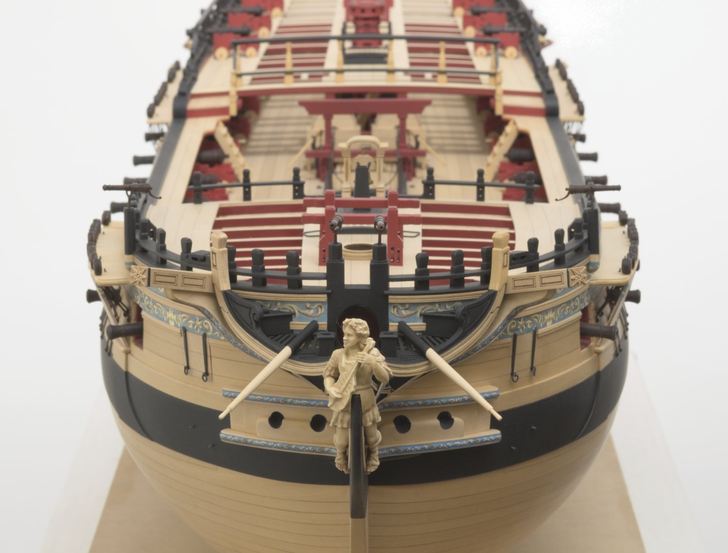
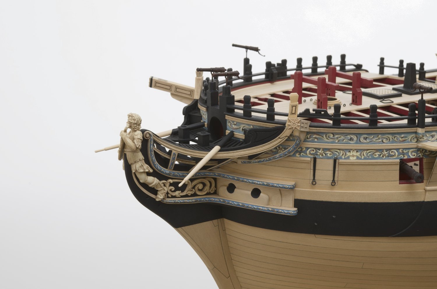
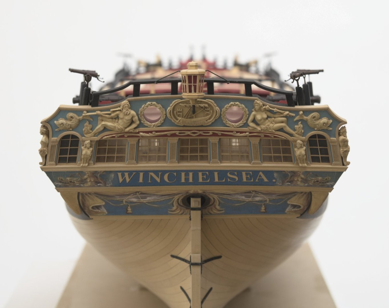
I completed the bumpkins which were the last of the parts which needed to be made. I decided not to drill the hole through the hull moulding and frieze. It felt that it was a little to risky at his stage of the build. Of course I never thought of it, but if it were possible I would have done so earlier in the build. Instead I simulated as best I could the look of doing so. Its been nearly five years since I switched from the 3/16" to the 1/4" scale version in April of 2018. With the ship now finished, I just want to say thank you for sharing this journey with me. Every kind word, comment and "Like" inspired me to do my best and keep moving ahead. I would be remiss if I didn't give a special thank you to Chuck for being a huge help to me from the very start as well as putting up with all of my nuttiness. Thank you, Chuck! See ya soon, Mike


- 607 replies
-
- 29
-

-
-

-
- winchelsea
- Syren Ship Model Company
- (and 1 more)
-
Just wipe of any excess dust with a paper towel. You don't have to remove every speck. Apply the Poly with cheese cloth and wipe off excess with the same.
-
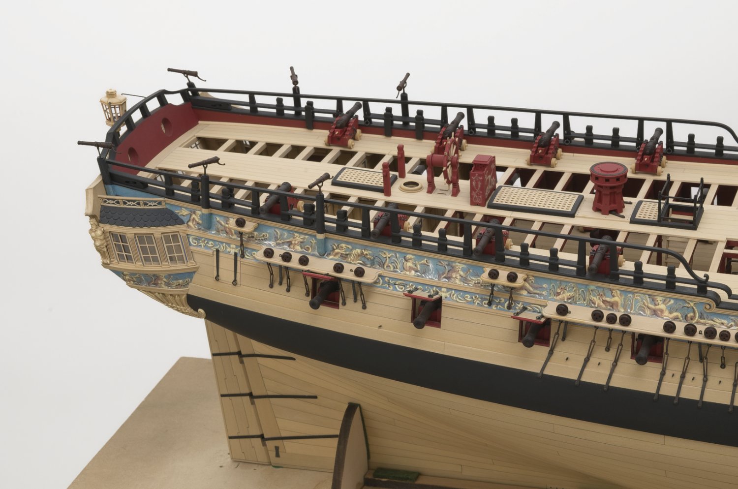
Continuing on with another small update. The aft seats have been added to the ship. This was tricky stuff and there were a few attempts needed. So, yeah, Nothing new. I used a tapered a dowel inserted into the hole as a helping hand when test fitting and gluing them in. Only a small amount of PVA at the notch surrounding the moulding and along the edge that sits against the false rail. Mike
- 607 replies
-
- 17
-
-
-
- winchelsea
- Syren Ship Model Company
- (and 1 more)