Stuntflyer
-
Posts
1,198 -
Joined
-
Last visited
Content Type
Profiles
Forums
Gallery
Events
Everything posted by Stuntflyer
-
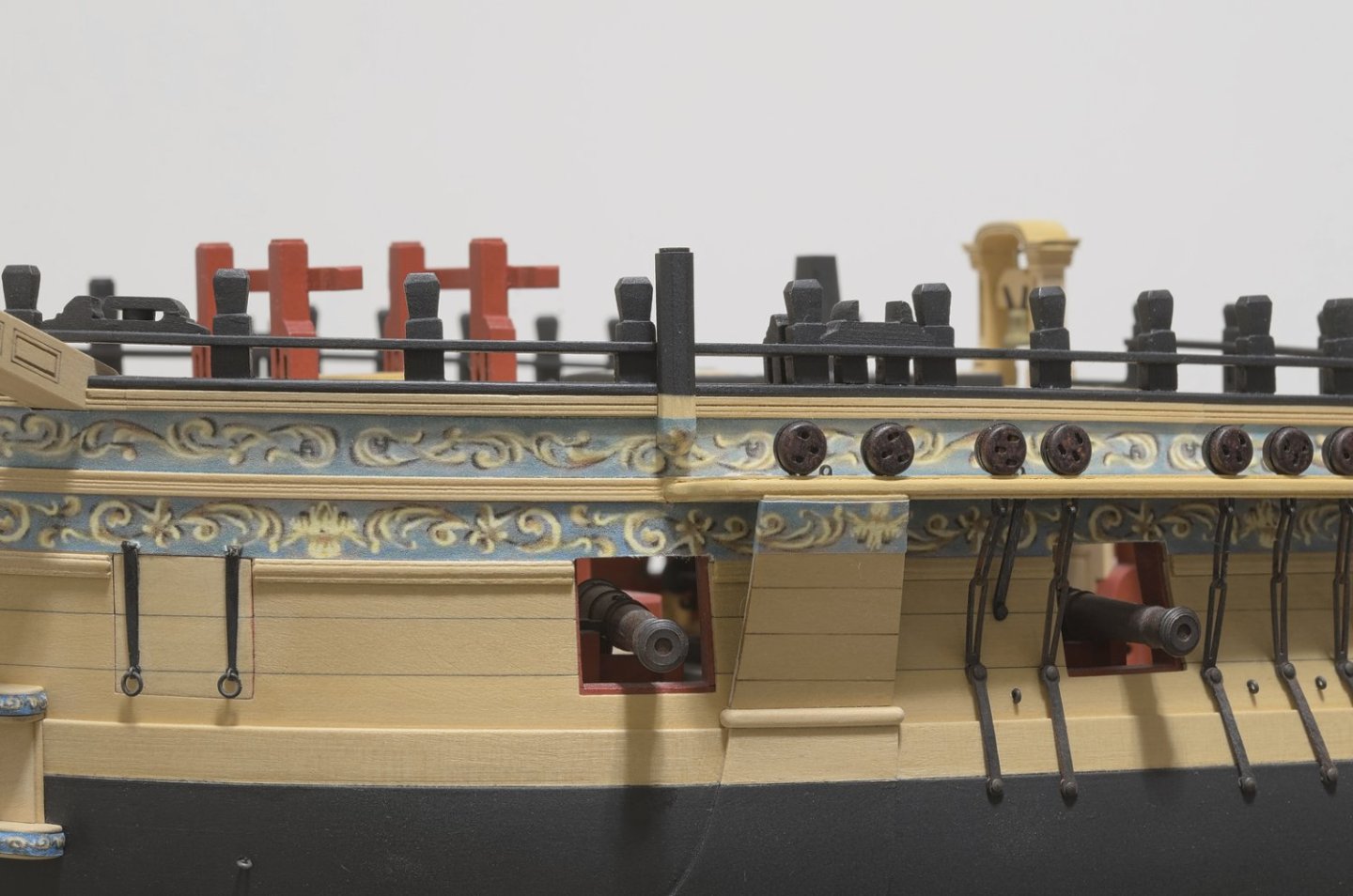
 I finished up the second main rail today. More black touch up needed and then onto the head timber cover boards. Mike
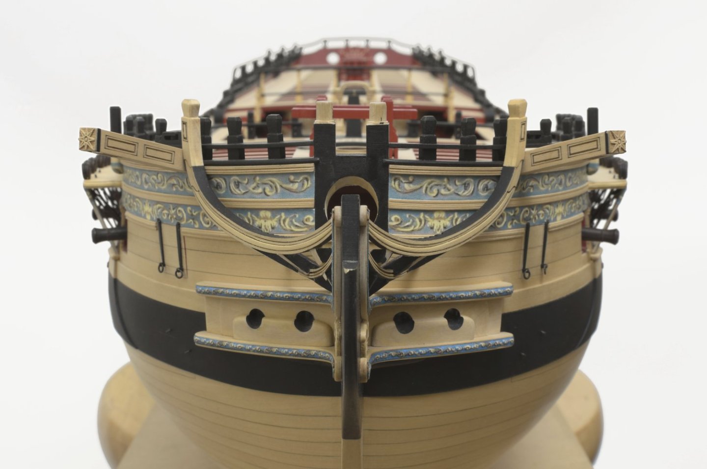
- 607 replies
-
- 29
-

-

-
- winchelsea
- Syren Ship Model Company
- (and 1 more)
-
Joe, be careful of doing that as an answer to the problem. There can be huge variations in color within a given sheet, some of which are not that visible. Just place all the strips flat on a table, edge to edge, and then W-O-P all the sheets to see what you've got. I usually hold the strips together with long pieces of tape. A straight edge at both ends holds things down.
- 642 replies
-
- 1
-
-
- winchelsea
- Syren Ship Model Company
- (and 1 more)
-
Is this a straight taper or does it curve?
-
Thanks!! I'm hoping for the good result. Time will tell.
- 607 replies
-
- 3
-
-
- winchelsea
- Syren Ship Model Company
- (and 1 more)
-
Happy Thanksgiving!
-
Nope, never did finish it. Hopefully, you will take it further than I did. Thanks for following. .
-
Hi Rusty, I had the same thing going on with my gun deck planking. I don't think it's absorption that's causing the variance in color, but rather the planks being of a different color to begin with. The degree of color difference would be difficult to see whether you sand the wood or not. The only way I know off to get around this is too apply some W-O-P to the planks before you put them on the ship.
- 642 replies
-
- 4
-
-
- winchelsea
- Syren Ship Model Company
- (and 1 more)
-
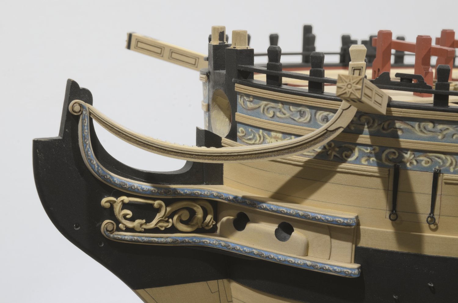
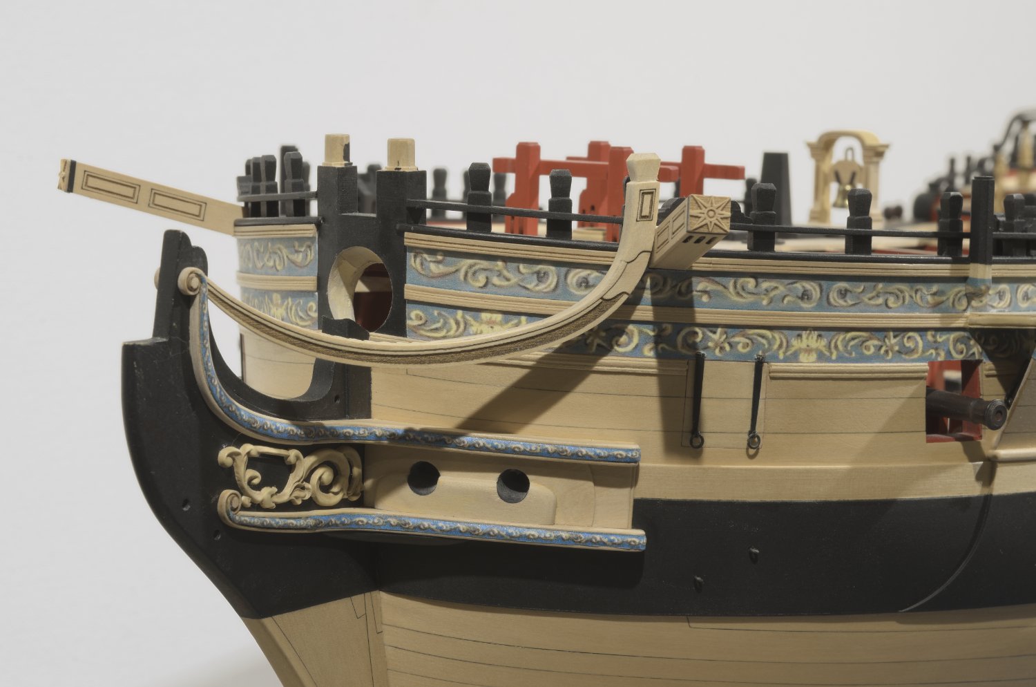
I'm making slow progress on the head rails. There is a lot more going on here than I thought. I struggled initially to keep things in place with rubber cement in order to view the relationship between the head timbers. Chuck suggested that I could set the center head timber vertical and then work the other two head timbers in such a way that it would look okay to my eye. With that in mind I did just that. After setting the middle timber I could see that the front one could lean slightly forward. I removed the fore end of the template which lies in front of the notch. A thin strip was placed between the back of the head timber and the template to angle the timber forward while at the same time keeping it parallel to the center timber. The aft head timber was angled slightly rearward. I can now use this as a guide for the other side. Btw; notice the position of the main rail in relationship the timberhead on the forecastle just behind it. This worked out okay on my Winnie, though that might be different on your ship. Mike
- 607 replies
-
- 22
-
-
-
- winchelsea
- Syren Ship Model Company
- (and 1 more)
-
I felt the same way at first only to eventually find out just how useful they can be. You could start small. https://www.leevalley.com/en-us/shop/tools/hand-tools/miniature-tools/chisels/72391-veritas-miniature-chisels?item=05P8501
-
The only experience I've had is when I worked on Hayling. I used the mill and a chisel for the deadwoods and it was not hard to do. Doing the work with just a chisel is not something I would have felt confident about. The cant frame angles where done with the disc sander. A machinist square was used to check positioning. I think this is a very good way to go about it as long as one has the tools. https://modelshipworld.com/uploads/monthly_2017_07/_DSC7015_sfw.jpg.18912c6b190c9821774c65e2d545a7d3.jpg
-
Thanks, Fred! If the second eye goes like the first, I will be extremely happy.
-
Not to worry, Chuck. After more than 4 1/2 years, I'm not about to rush the Winnie to completion. At the moment, I'm half way through my cataract surgery and get this. . For the past 3 years I thought that the background color of the frieze was predominately green. I was shocked to see otherwise. That's how much my eye lens had turned yellowish over the years. CRAZY! I will start again on the Winnie in a few weeks after the second eye is done. I am very excited about being able to collaborate with you on the project. There will be so much to learn and that's half the fun. Looking forward to seeing you and the guys after TG.
-
Chuck, it's great to see that you're starting another great project. One that will allow you to innovate and be more creative than ever. I should be ready to start Speedwell by years end or shortly thereafter. My plan at the moment is to go with boxwood. Of course, this will make me an outlier with my own set of challenges. Good luck with everything! Mike
-
Most likely no issues at all since you went to 3/16” at the deck level. However, as Chuck suggested, 5/32” or so at the deck level and taper to 1/8” at the sheer. If it is not too late then that is something you could do now. keep in mind that 3/16" at the sheer will most likely produce a cap rail that is too wide. Going wide at the gun dock could mean that certain laser cut parts might not fit properly. The checkerboard floor is one thing that comes to mind. Also, the bulkheads for the great cabin area might be too narrow to span the deck. Planking widths on the deck will most likely have to be modified. These are just a few examples of what could happen by simply reducing the width of the bulwarks to 1/8” or less at the deck. Mike
-
Glenn, As Chuck just pointed out, do not fair to 1/8" all the way down to the deck level. If you do that, there will be a few issues to deal with later on in the build. Trust me, I've been there! Mike
-
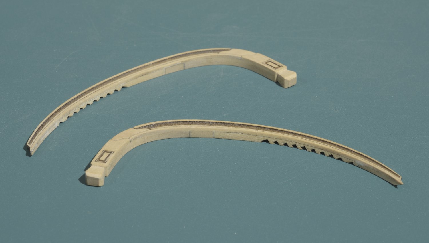
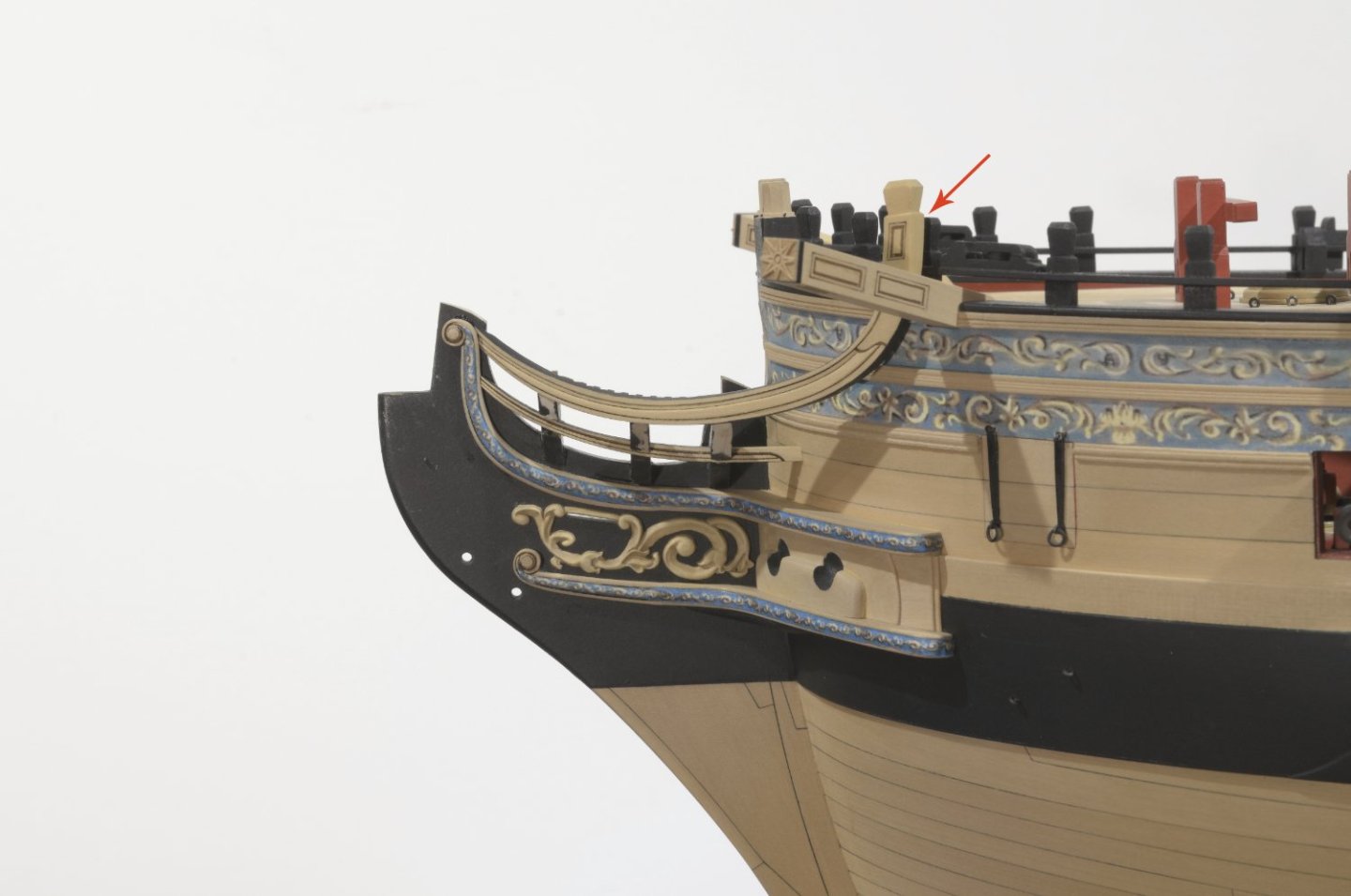
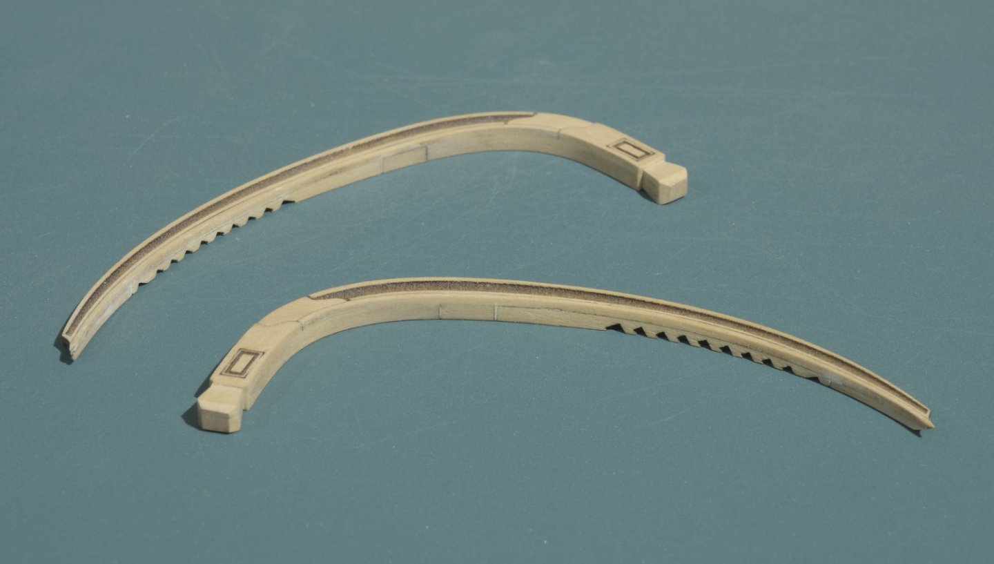
Thanks, Chuck! It was great getting back to a Saturday get together at your place. Nice to see old and new faces too. I'm starting chapter twelve with the main rail. This is my first try at doing rails. I can only imagine the difficulties in doing them full scratch. After assembling the first six sections I measured the width at the timberhead. It was too wide and needed to be reduced to 5/16". First, the outer face was reduced slightly to create a more gentle transition between the parts. Then the inner face was tapered to 5/16" at the timberhead down to 5/64" at the forward end. As you can see, it's flat on the inner edge. The timberheads were then shaped. Here is the first test fit after setting the forward end and then removing a small amount of the cap rail and fancy moulding. With the rail in place the area I removed cannot be seen. I will probably need to remove a bit more from the back of the rail. It's a wee bit too tight going in right now. Mike


- 607 replies
-
- 22
-
-
-
- winchelsea
- Syren Ship Model Company
- (and 1 more)
-
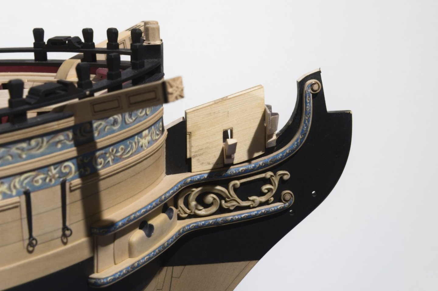
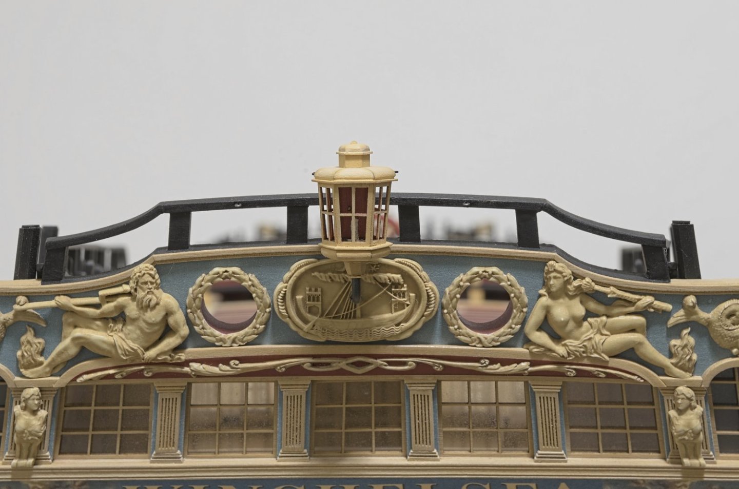
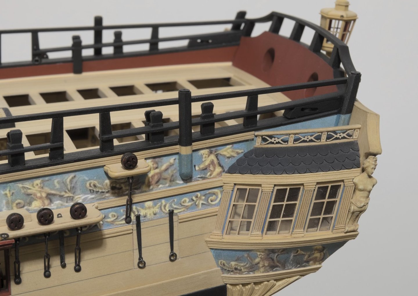
For the most part, chapter eleven is finished. As I mentioned earlier, the lantern is still removable. but, that's it. Without any adjustment the forward stock will angle out. I undercut the inner face and tapered it in order to make it sit more upright, basically perpendicular.. Mike
- 607 replies
-
- 19
-
-
-
- winchelsea
- Syren Ship Model Company
- (and 1 more)
-
Another small update on chapter 11. The lantern as seen here is removable from its support which was made from blackened 1/16 brass rod. The two 24ga wires that go from the lantern to the transom rail are omitted for the time being. I'm concerned about the lantern getting knocked about in transit, so I left it removable for now. I started on the swivel stocks. The first four are now on the ship. Mike
- 607 replies
-
- 18
-
-
- winchelsea
- Syren Ship Model Company
- (and 1 more)
-
Another beautiful model from a master builder. Now, take a well deserved vacation and come back refreshed and ready to start the next project. Mike
- 1,784 replies
-
- 5
-
-
- winchelsea
- Syren Ship Model Company
- (and 1 more)
-
Your model looks great! Feel better soon.
- 642 replies
-
- 3
-
-
- winchelsea
- Syren Ship Model Company
- (and 1 more)
-
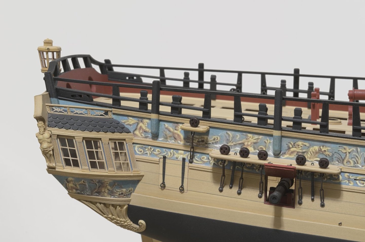
Just a quick follow up on my last post. I changed the position of the fancy rail after realizing that I originally placed it incorrectly. Mike

- 607 replies
-
- 13
-
-
- winchelsea
- Syren Ship Model Company
- (and 1 more)
-
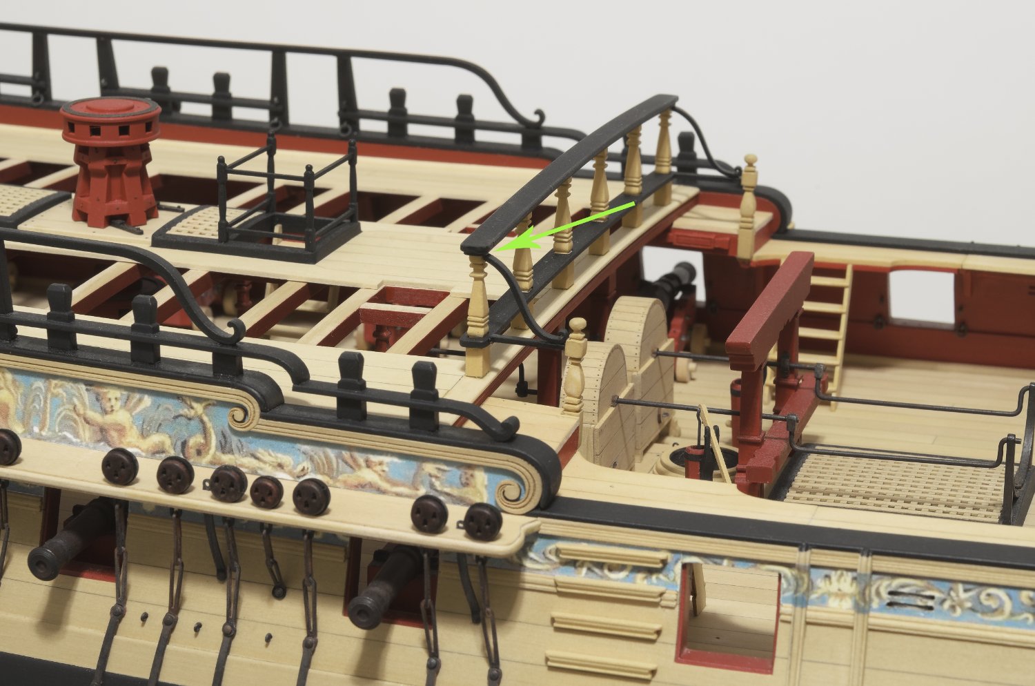
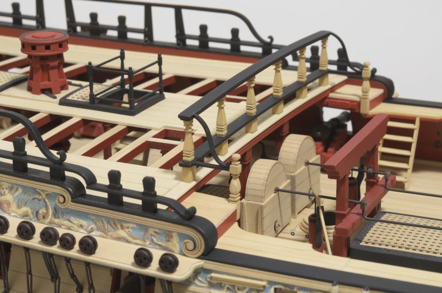
Progress has been really slow lately. I did manage to get the so called newel posts and fancy rails completed. I re-installed the QD rail, but this time I pinned all six posts. All that's left to do in chapter eleven are the swivel gun supports. Hopefully, I will get an adrenaline rush and finish those up soon. Mike
- 607 replies
-
- 23
-
-
-
- winchelsea
- Syren Ship Model Company
- (and 1 more)
-
Thank you all for the likes and kind words. Very much appreciated!
- 607 replies
-
- 1
-
-
- winchelsea
- Syren Ship Model Company
- (and 1 more)