Stuntflyer
-
Posts
1,198 -
Joined
-
Last visited
Content Type
Profiles
Forums
Gallery
Events
Everything posted by Stuntflyer
-
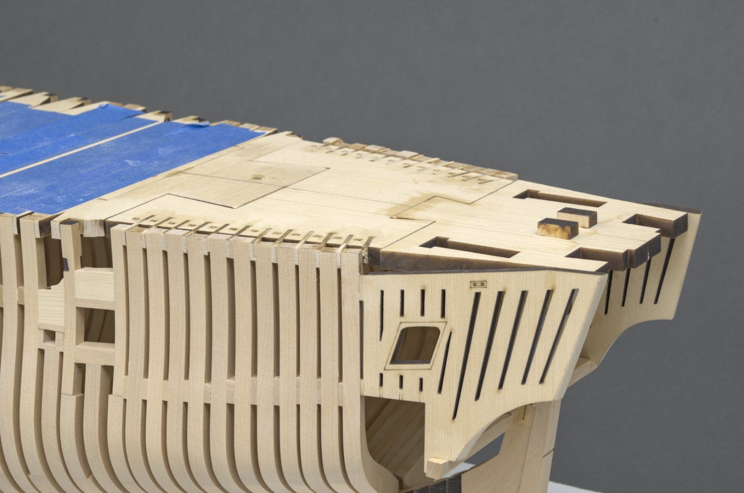
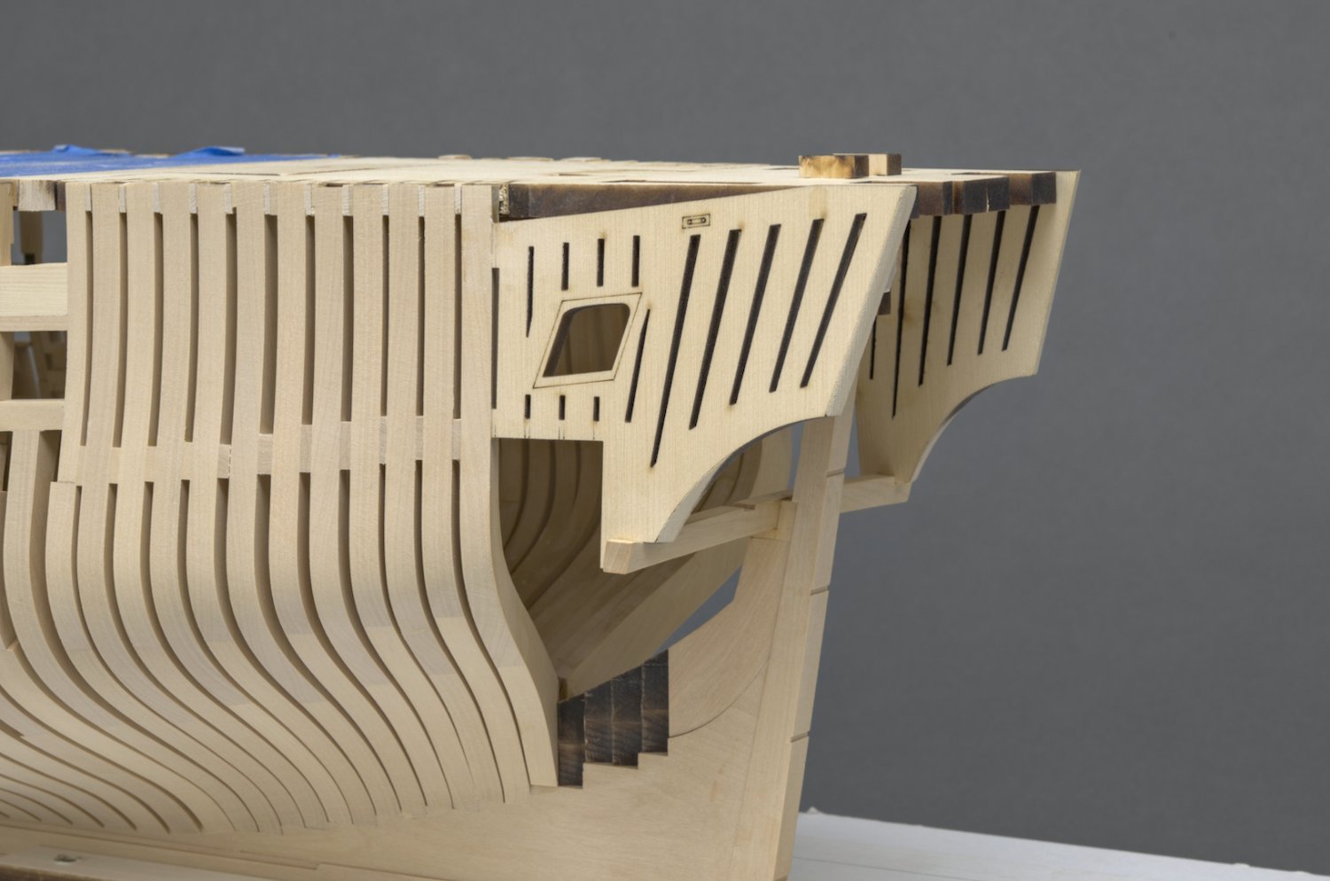
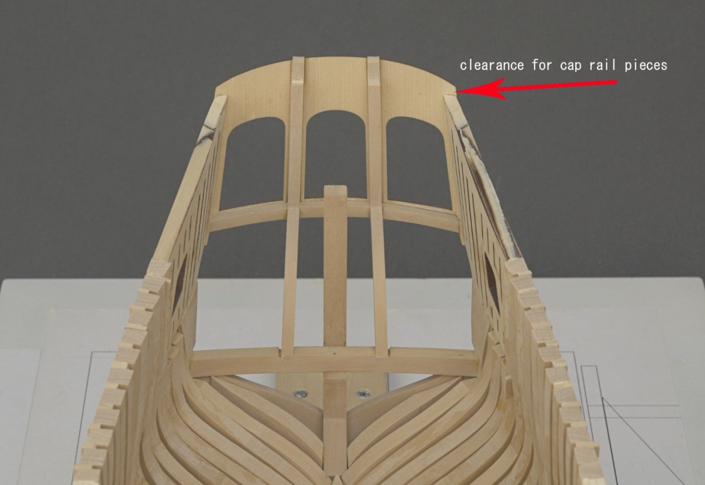
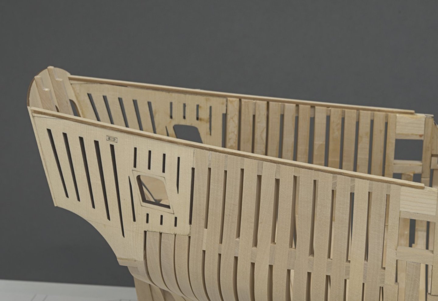
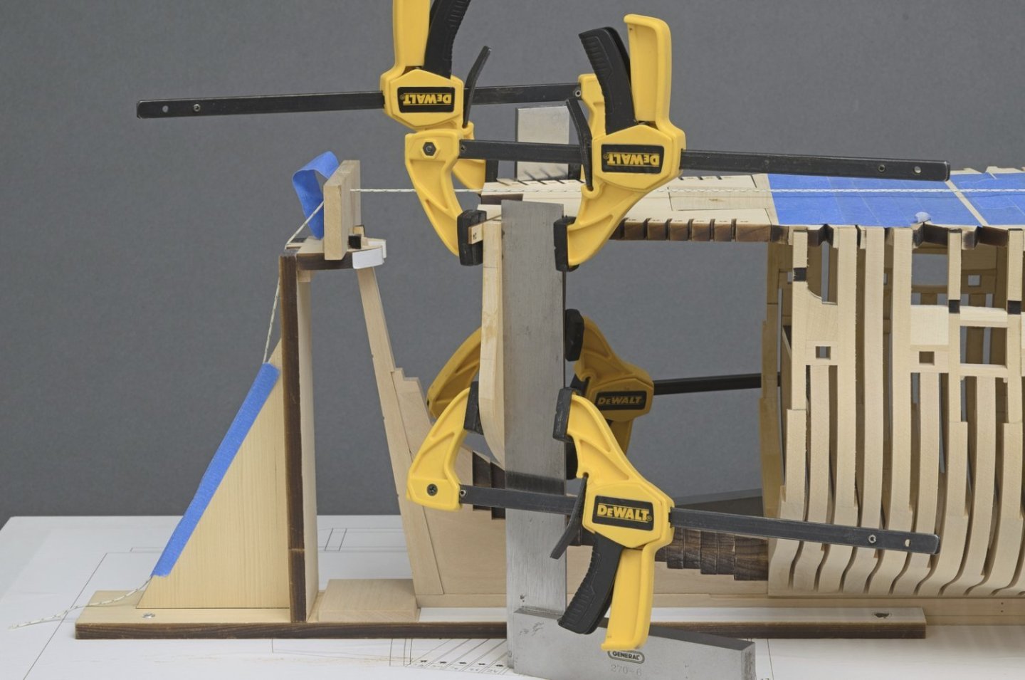
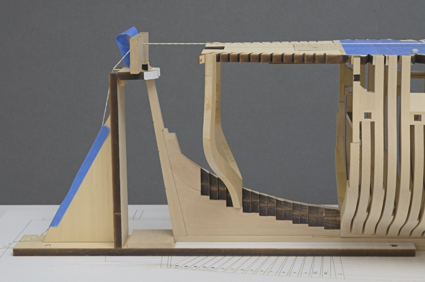
 Window sills I will admit that these were quite tricky to make. Different angles everywhere and some trial and error was needed in order to get them just right. I probably had 3 or 4 throwaways before getting the ones you see here. Stern frames In order to make these, I sandwiched two roughly cut frames together with some Elmer's School Glue and then adhered the plan drawing for final shaping. This was easy enough to do with the help of the spindle sander, disk sander and scroll saw. Transom On top of the shear there will be a 5/32" fairing cap and a 1/4" cap rail that sits on top of that. The two pieces will add a total of about 3/32" more height to the top of the shear. I wouldn't want the cap rail to protrude above the top edge of the transom. With that in mind, I decided to fair the quarter deck shear before adding the transom. This way I could check the clearance before adding the transom. It was really just a matter of getting that small triangular piece taken down to the right height while fairing the shear. I added the 5/32" fairing cap for the quarter deck and faired the outer hull using the cap as a guide. Mike
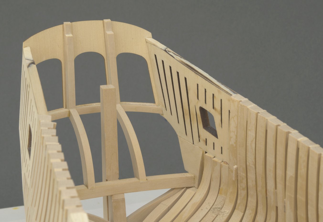
-
FWIW, I'm not sure that will work out. I looked at mine a few minutes ago and the all red base for the skylight looks right. Place a few simulated planks around the skylight, just to see how it will look once the deck is in. Mike
-
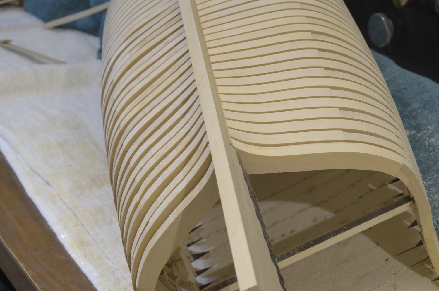
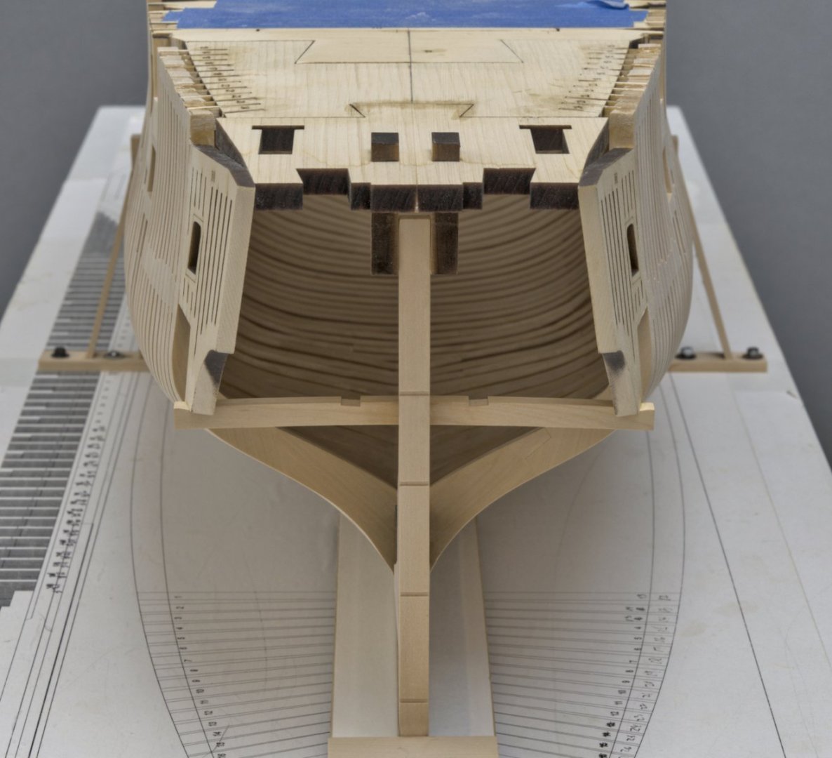
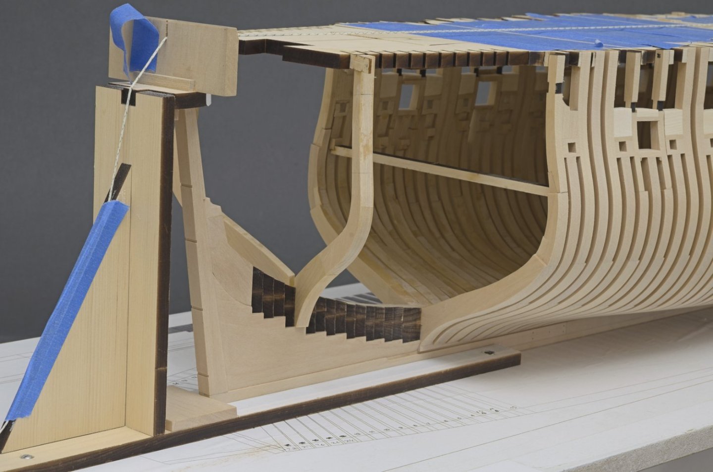
Framing (final pieces) I have finally finished all of the framing. About nine months to do them all including about 160 milled scarph joints. It certainly feels like a milestone. Though mostly done, I still need to do some minor cleanup fairing, especially where the cants transition into the deadwood. FYI: Here is the fit that I was shooting for when adding the last frame, #29. Mike


-
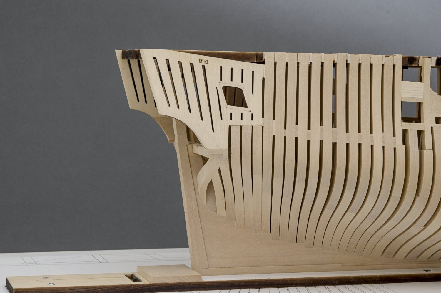
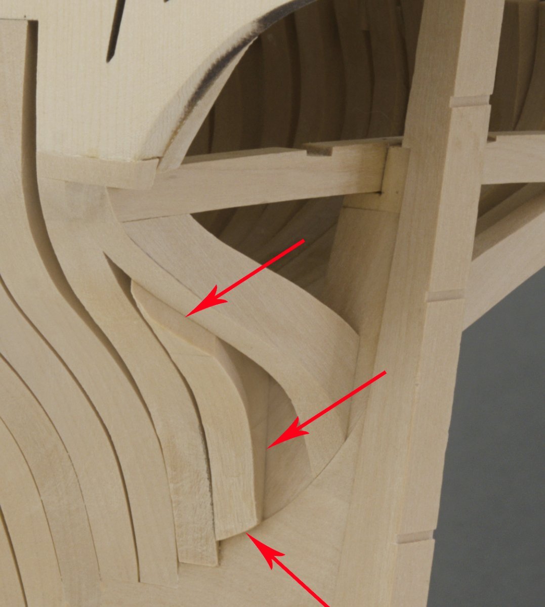
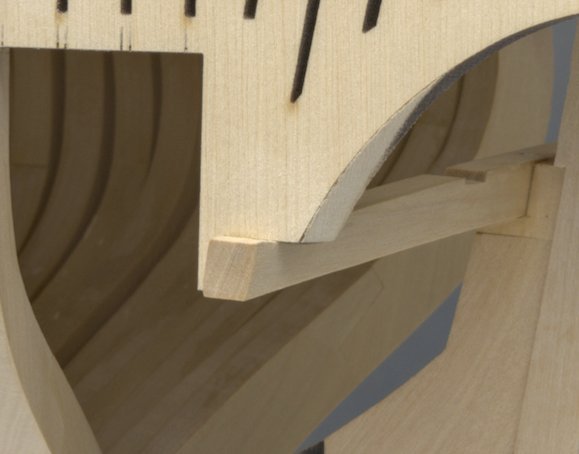
I was hoping for a little more progress this week. The problem was that I started nit picking. One of the things that I've been wanting to do from the beginning was to avoid any color matching with paint for areas that might not have turned out as expected. Typically that would be something like an open butt joint or where two different wood types join together thus changing the uniformity of the look. Looking at this closeup photo from my previous post, it's not hard to see that the AYC quarter panel is a lighter color than the end grain of the wing transom which is made from boxwood. The lower section of the quarter panel for the most part is covered by planking. However, some of the lighter AYC color will be seen after the planking is completed. Knowing that, I decided to remove some of the AYC from the quarter piece and replace it with boxwood. Actually, it was quite easy to do and I was able to complete the work in less than an hour. See photo below. Fashion piece The fashion piece was cut from 5/32" sheet. The tricky part was getting a nice flow into the bearding line and a good joint along the deadwood and wing transom. I ended up having to make two of these in order to get the one I liked. I left the top of the fashion piece standing proud. Also, I left some of the paper template attached which could be used as a sanding template. I recommend doing this rather than trying to get a perfect fit everywhere. It's hard to explain as to why, just that it's easier to fit the piece and fair the top into the wing transom afterwards. If I end up back into nit picking mode, I might do a bit more work at the bearding line transition. Also, note that the boxwood filler is in and mostly faired. Mike
-
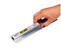
Another way would be to place a flat sheet on a flat bench or table so it hangs over by a wee bit. If you're right handed, place the sheet on the "right" side table edge. That makes it easier to sand the sheet without having to twist your body. Tape down the edge sitting on the table. Round off the over hanging edge using the 11" bar sander like this one from Great Planes. After that you could rip the rounded strip away from the sheet with the table saw or cut if off the sheet with a #11 blade.
-
Nicely done!
-
Thank you all for the kind words, and for all the “Likes”. Very much appreciated.
-
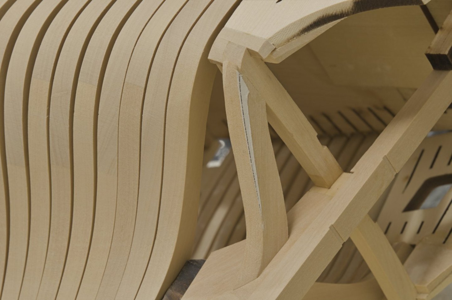
Wing transom and quarter panels The wing transom is made from 5/16" sheet. Using the template from the plan sheet, I cut out the basic shape and then milled the four angled notches. The templates for the remaining curve shape (forming that parallelogram shape) are on the plan sheet as well. I just copied what Chuck has described in his build log on page 8, post #228. The wing transom was pinned with 24 gauge wire and glued to the deadwood. The pinning was done to make it easier to set the height of each end and fore/aft positioning without having to worry about it sliding back and forth at the same time. After the wing transom was installed I started work on the two quarter panels which attach to the wing transom. What is important to note is that the cant frames should be fully faired prior to installing the quarter panels. I worked on this until I got a smooth transition between the last aft cant and the quarter panel. Once that was done, I glued the panels in place. Mike


-
Chuck, you certainly have my 👍 on the transom work. Those figures look great, beautifully done!
-
Happy Thanksgiving, everyone! I'm finally over a bad cold which prevented me from fairing those aft cant frames sooner. With so much wood to remove, I decided to stay with the adhesive backed 80 grit sandpaper until final cleanup. No doubt AYC would have been much easier to deal with than boxwood. Still, no complaints! Mike
-
I could be wrong, but I think that Frank is talking about the hawse holes.
- 840 replies
-
- 2
-

-
- winchelsea
- Syren Ship Model Company
- (and 1 more)
-
Yes, the angles are tricky. Start with a small diameter drill. A round needle file helps as well.
- 840 replies
-
- 2
-
-
- winchelsea
- Syren Ship Model Company
- (and 1 more)
-
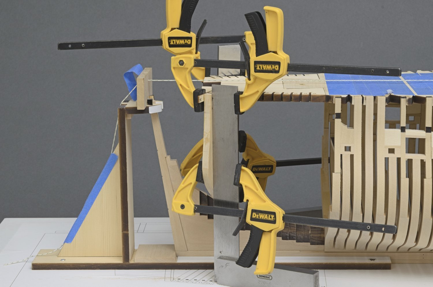
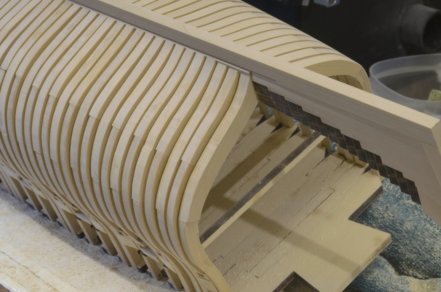
I've been moving right along on the aft cant frames. Just like the fore cants, there is a long span between the upper and lower attachments which results in some flexing. To stiffen things up I placed chocks between the frames. This will help greatly to keep the frames from breaking loose while fairing. The chocks were placed in the area between upper wale and the lower planking strake. They will be completely hidden. Mike
-
Brian, There will be quite a bit of interior details. I have not seen the plans for that, so I can't say exactly what details will be on the ship. Erik, I do try and get everything right when I install a frame. Using the machinist squares makes it rather easy to accomplish this. Something I like to do is to adjust the foot of frame to sit flush into the deadwood with no gaps showing. I'll use the disc sander for this, hand turned. None of this is difficult, just takes more time. With so many parts and small details to look at it's hard to say just how much of this will be noticed after the ship is finished. Mike
-
Cant frames (aft) Framing continues with the install of aft cant #24. This is basically a repeat of what was done with the fore cants. Just less work overall. Anyway, here you go. Mike
-
Greg, thanks! Not knowing exactly how it was going to fair, I had a real sense of relief when it turned out okay.
-
Thanks, Chuck!
-
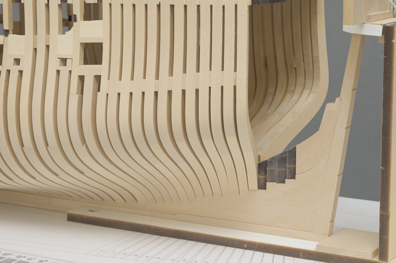
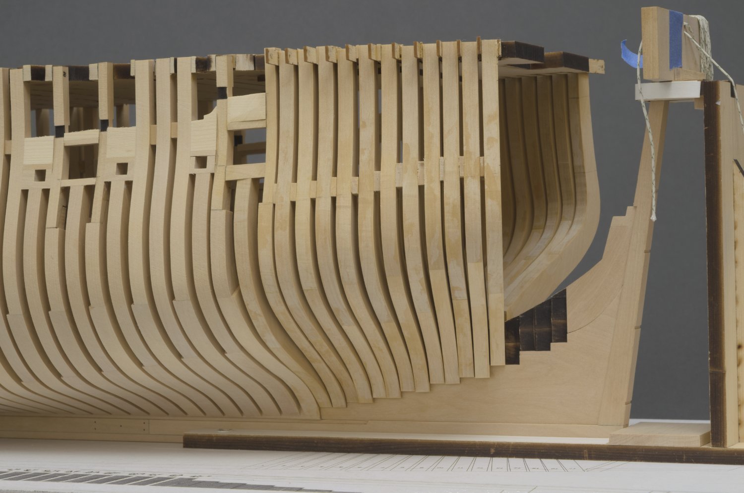
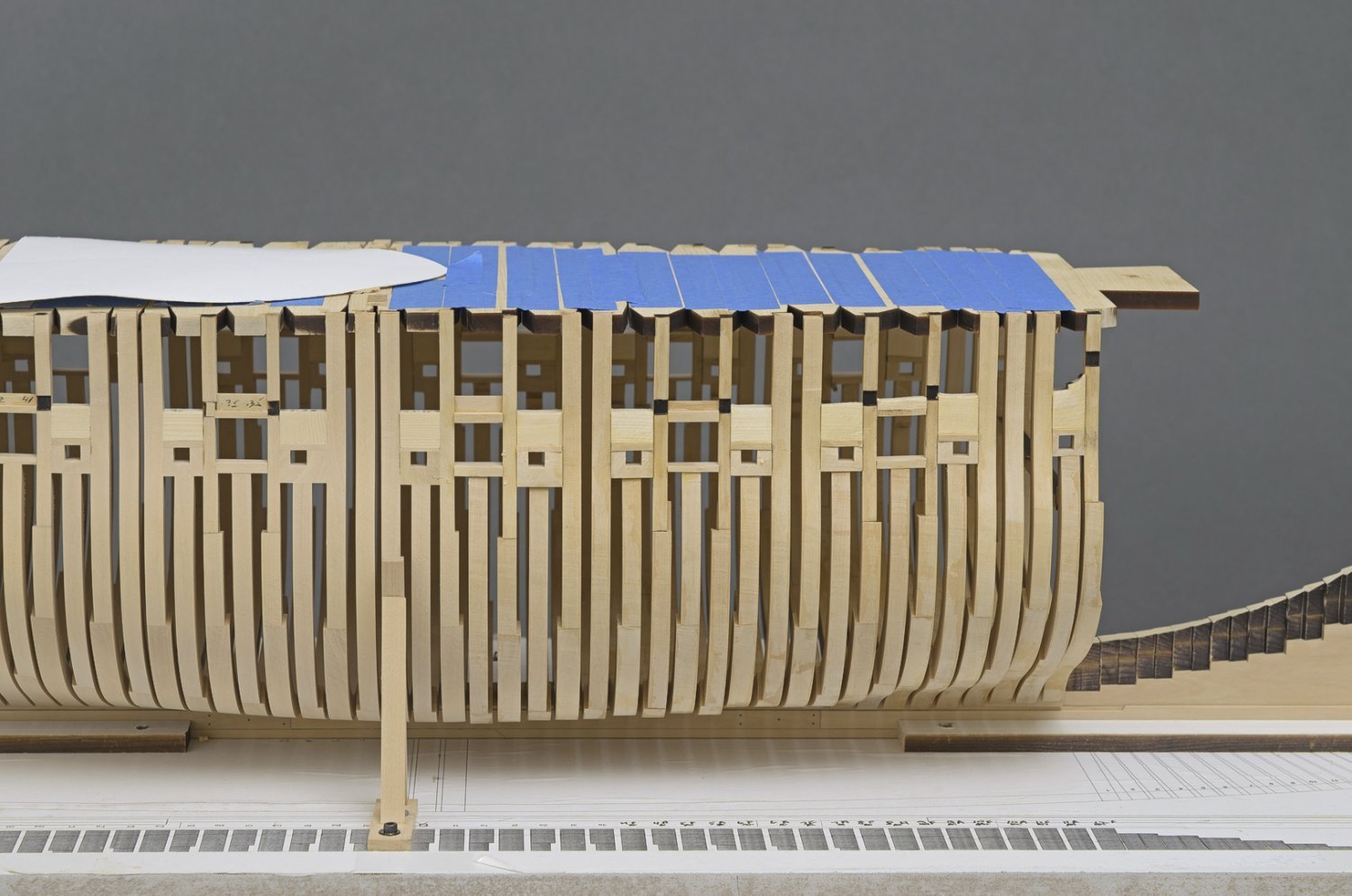
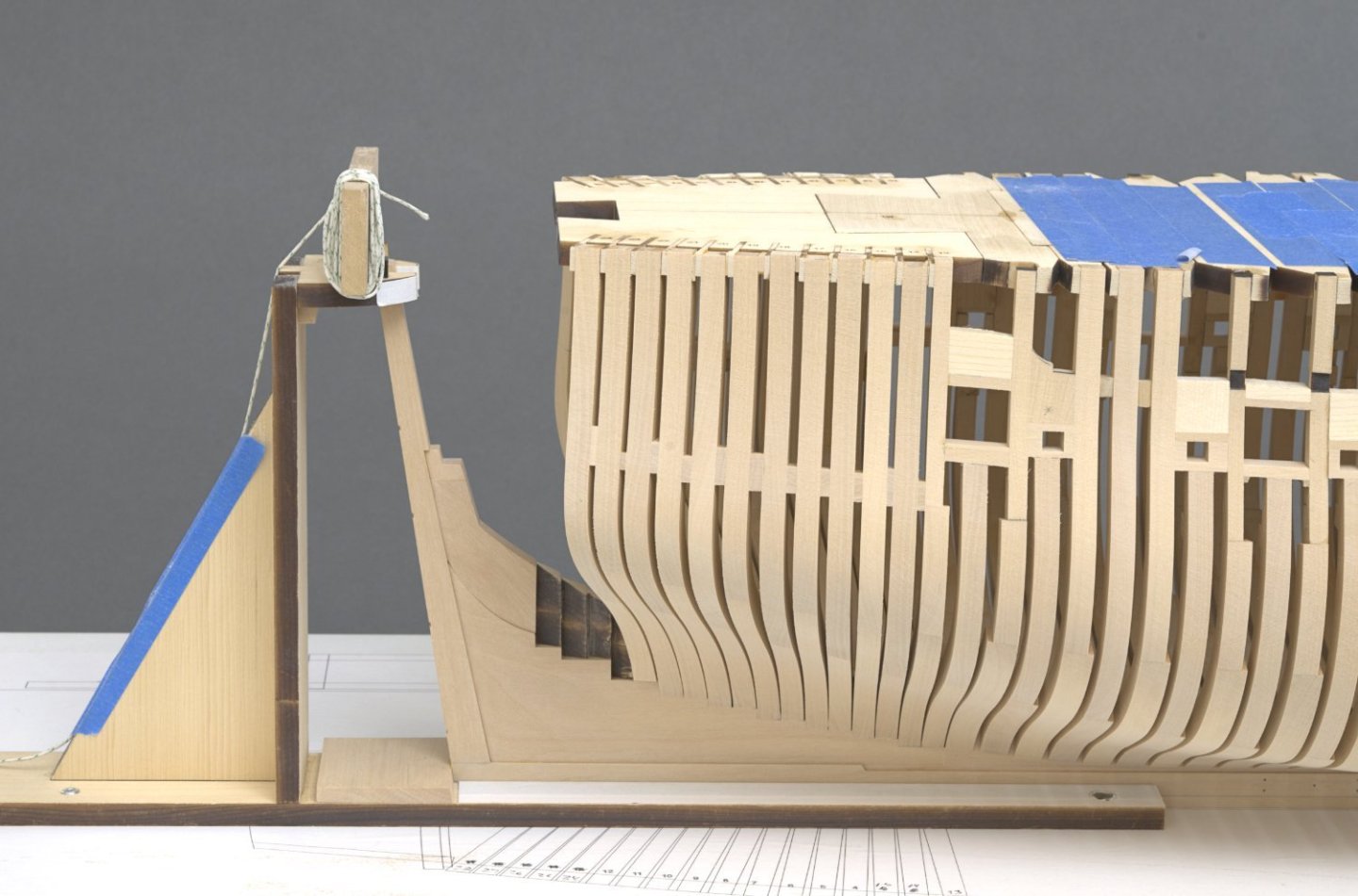
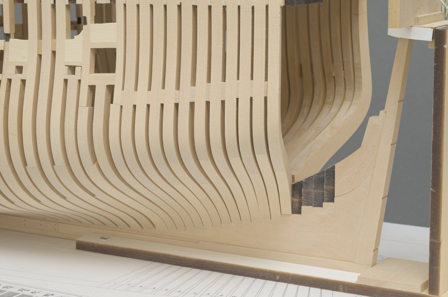
In spite of a mild case of vertigo, I managed to fair most of the port side frames. I purposely left the last 2 or 3 aft most frames partially faired. I recommend doing that in order to avoid any chance of over fairing when there are no additional frames to guide you. So, I will wait until I have some aft cant frames installed before I do any more fairing. I shot these photos to give you an idea of just how much wood needs to be removed. Judging from this, I am sure that the cants will require even more work. Mike

-
Whaat! Your not into selfies?😁
-
Welcome back Erik!
-
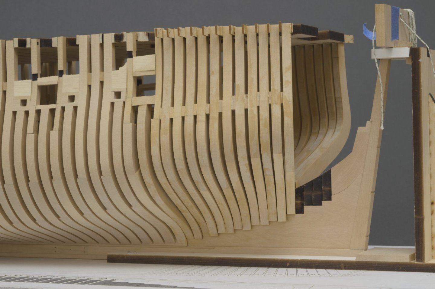
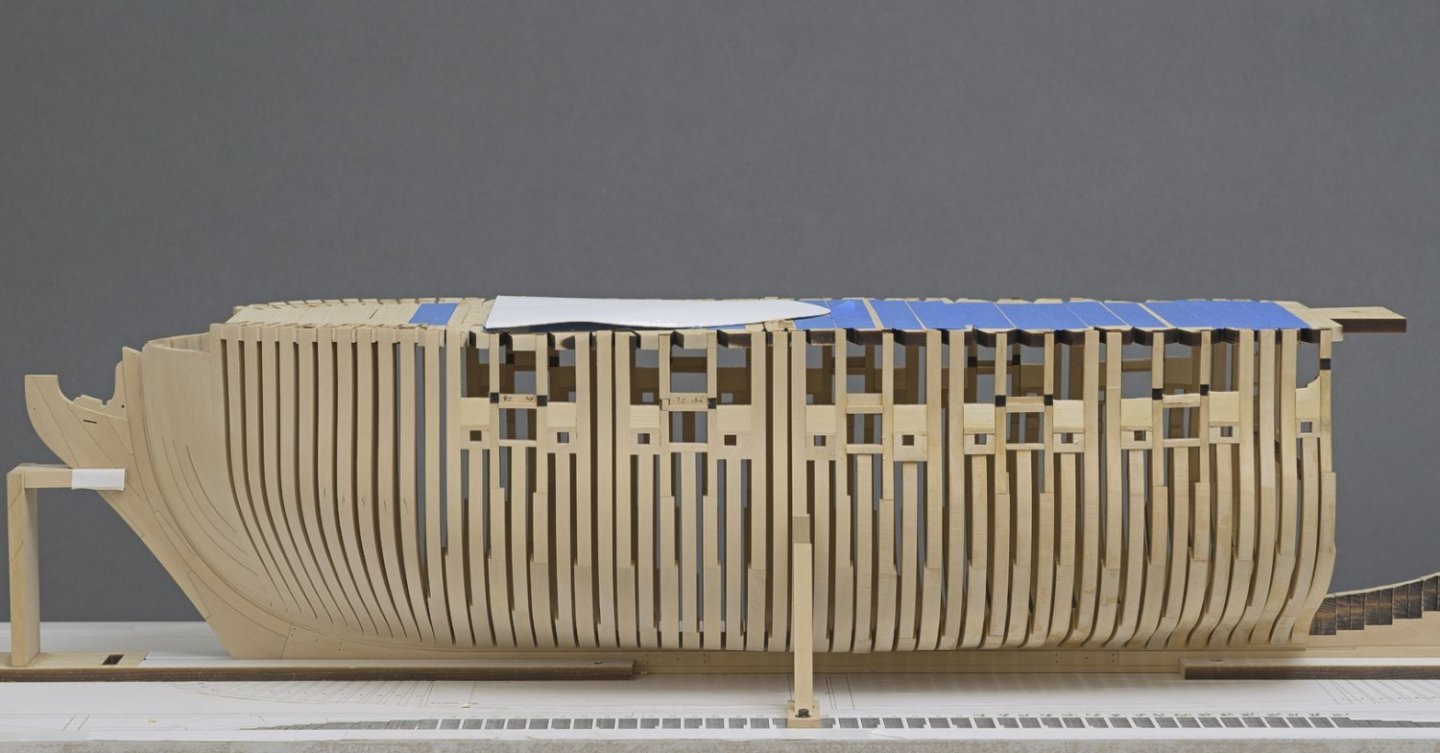
The last of the square frames were installed over the weekend. A little over six months for all the frames so far. Now the fun begins. Time to grease the elbows and start fairing. I'll be working mostly aft from the vertical support jig which is attached to the build board. Also I made tick marks on of a few of the cant frames that are in need of a bit more work. Mike

-
Oh, something I almost forgot to mention. A while back Tom (TBlack) asked me a question about the angle gauge on the tilt table attachment for the mill. He said> "Interesting setup, but you do have to trust the angle gauge to be accurate Any way to double check the angle?" See post 46 & 48. At the time I said that I trusted the gauge. As it turns out, Tom was on to something. The gauge is accurate as long as the pointer is positioned perfectly. That is not always possible and in fact it's a bit fiddly to work with. I discovered that my eyes could do a better job by using the uncut area of the milling bit to sight the lines on the frame drawing.
-
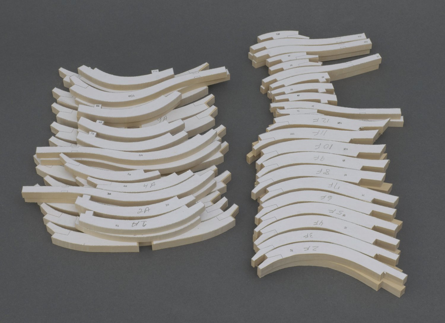
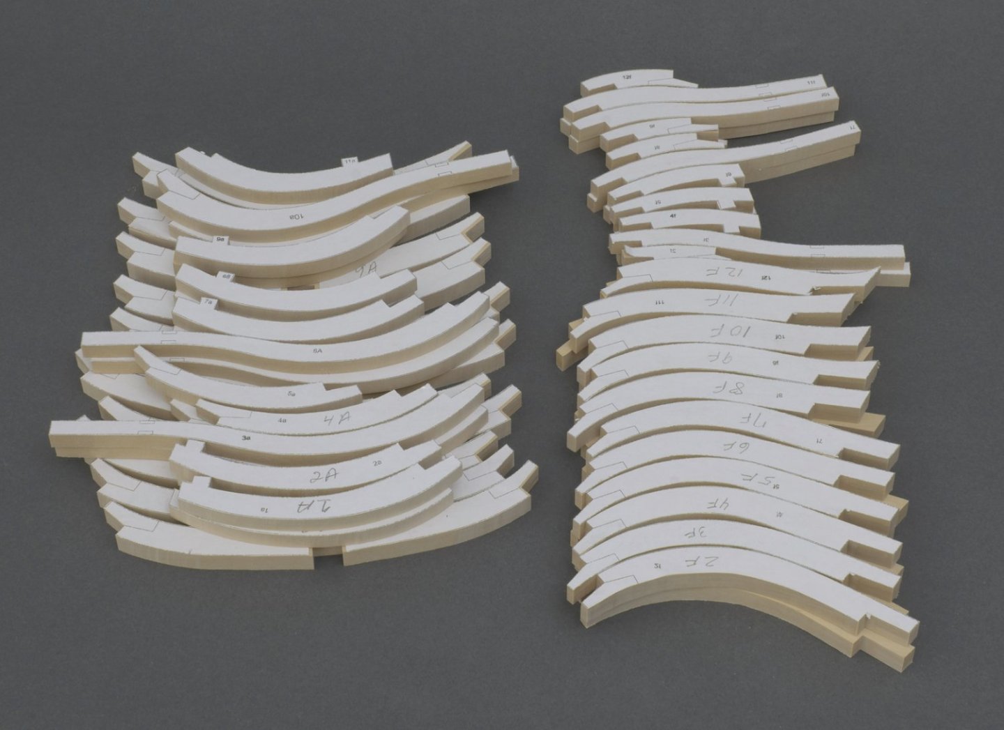
Square frames (pt. 2) Hi guys, Moving ahead I decided to cut out the remaining square frames from sheet and mill all 140 scarph joints. A real exercise in patience, like doing guns. Mike
-
Congratulations on a beautifully done Winnie!
-
I had the opportunity to visit Chuck last week. Photographs are always nice to look at, but being there is always better. At least when it comes to Chuck's Speedwell. He is using an advanced coloring technique to better mimic that of the contemporary model. The model has a subtle look to it where all the parts look proportional to one another and finely done. For example, the moulding that runs through the quarter badge is only 1/32' deep and the badges themselves are quite thin. I think it looks great! Mike