Stuntflyer
-
Posts
1,198 -
Joined
-
Last visited
Content Type
Profiles
Forums
Gallery
Events
Everything posted by Stuntflyer
-
 druxey, thanks for the tip!
 -
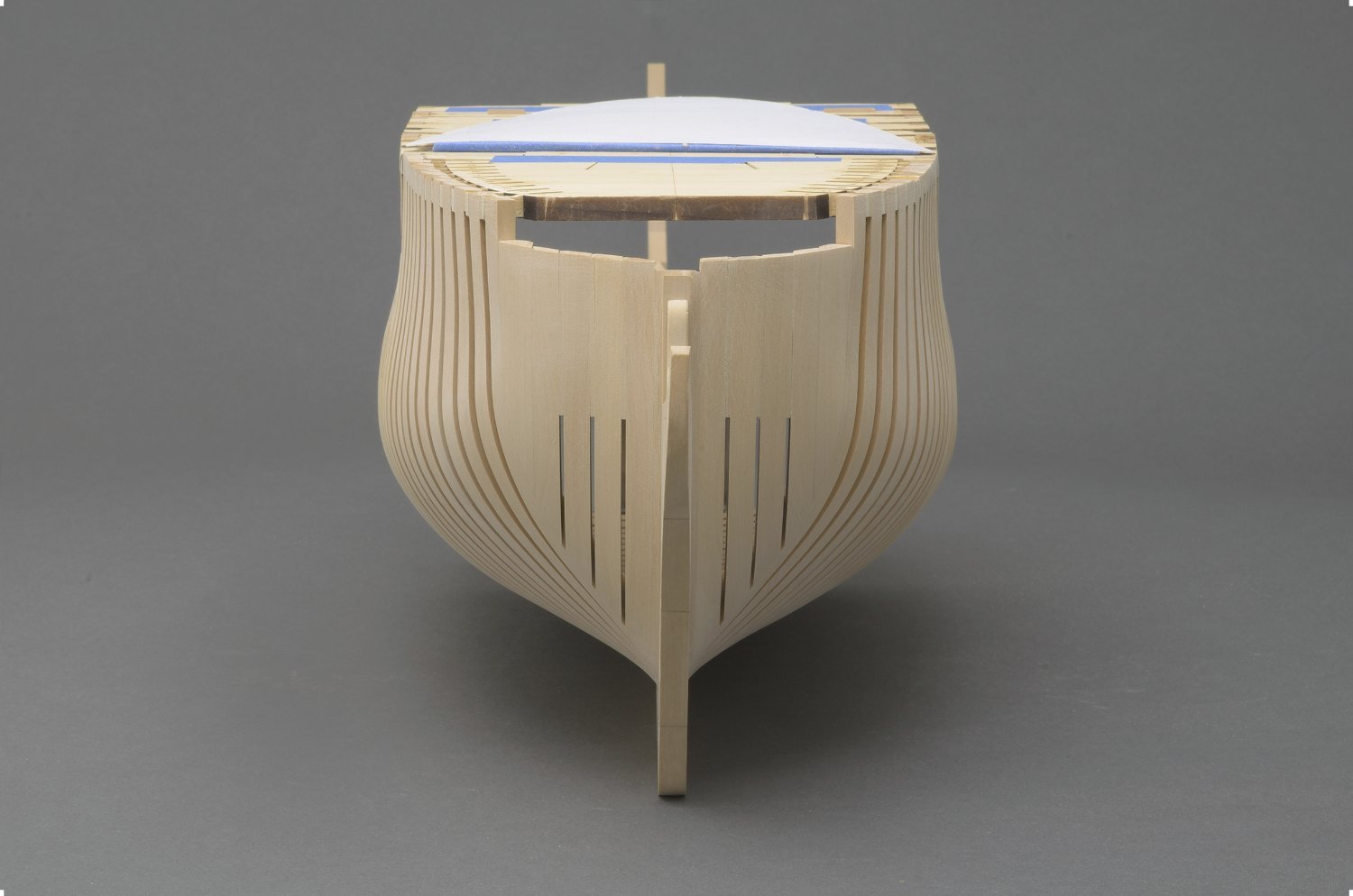
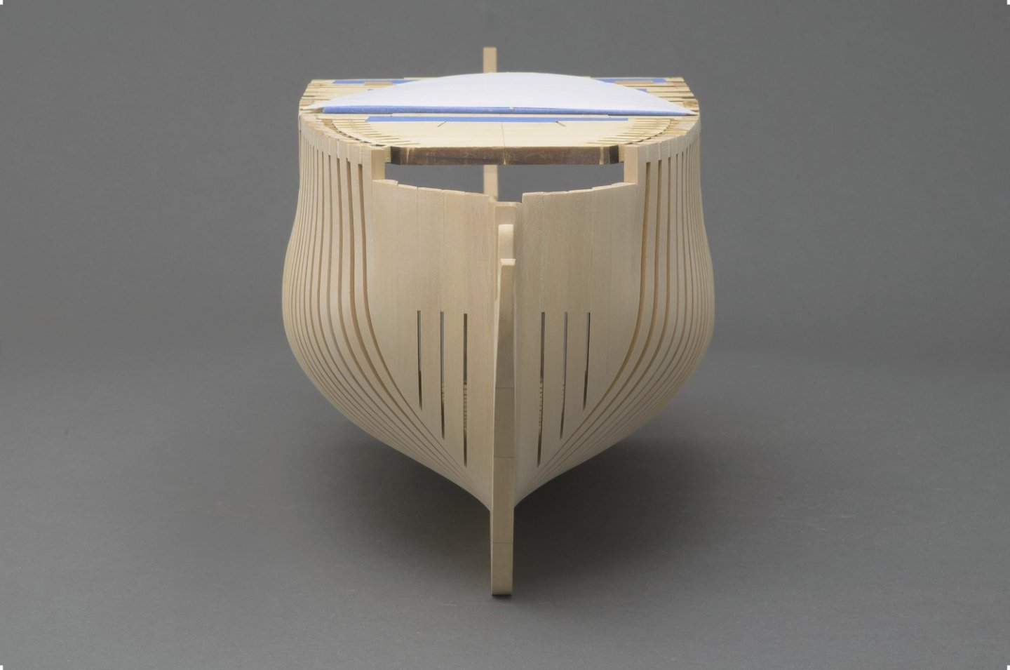
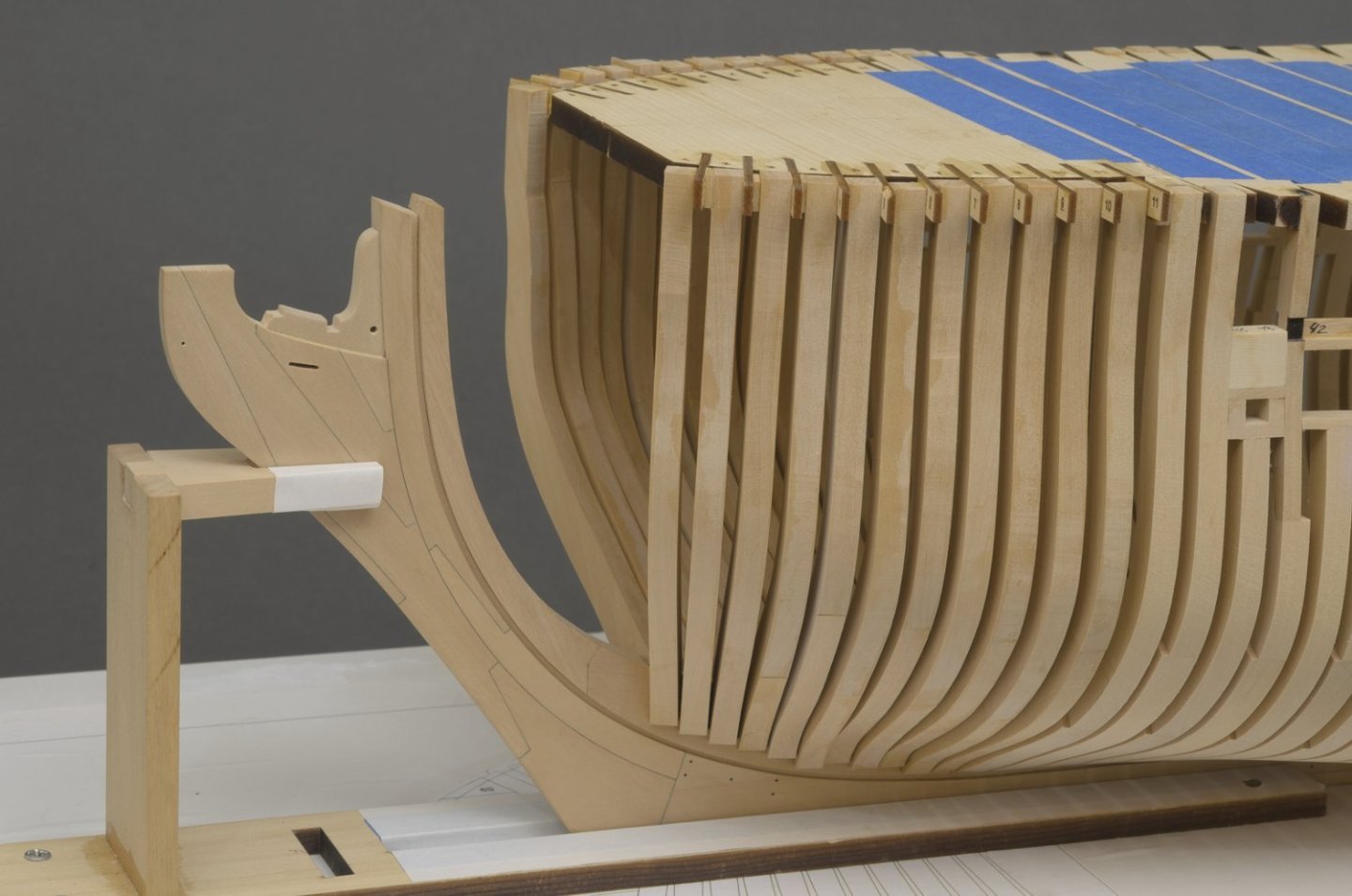
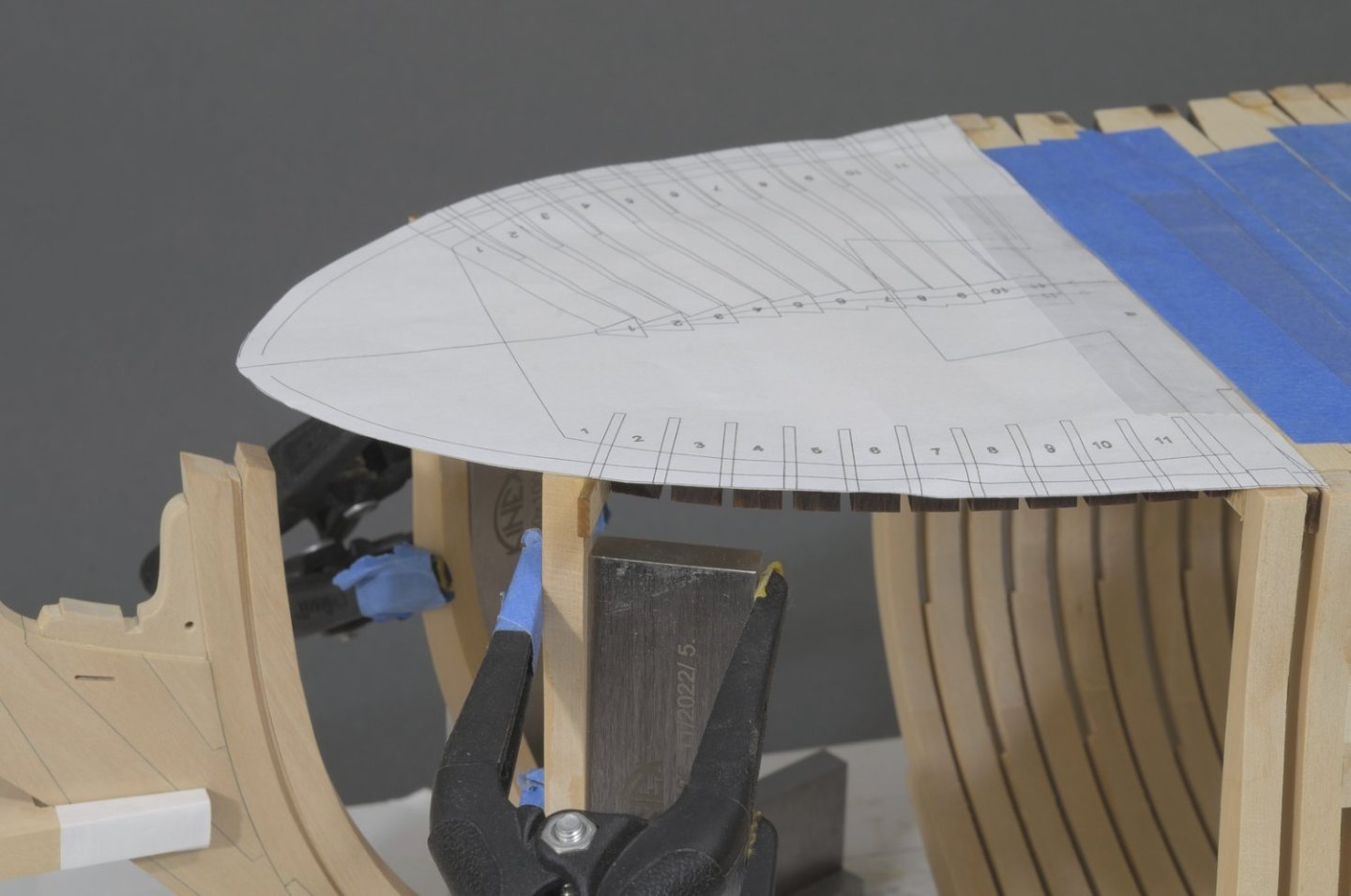
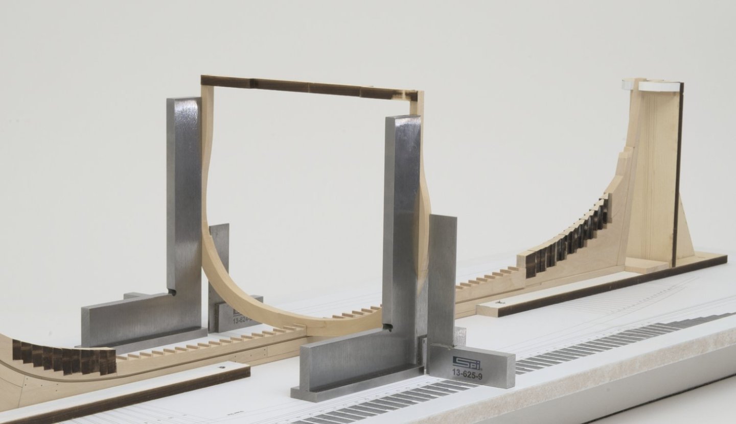
Bollard timbers More progress with the completion of the bollard timbers. I scratched these with the ongoing feeling that they might not work out for one reason or another. I did have to pull one along with the P1 filler piece, but luckily the glue hadn't set. What I found was that as meaty as these are at 9/32" that the wood would still develop a slight curl when using PVA. There was no good way to clamp pieces together. Generally I like to have some time to maneuver which the PVA allows for. In the end I went with slow cure CA. The paper template seen in the photo was stiffened with card stock. I flipped it back over the cant frames when I faired the curve of the top timbers, as seen from above. I can't stress enough how important it is to use it. It really does take the guesswork out of getting each side of the hull symmetrical. There is always more fairing to do though I think I'm close. Mike
-
I know exactly what you mean, been there myself. Trust me, your planking work will only get better. Still, you should be very happy with your result on the Winnie. Mike
-
Very nice, frank! you reached a milestone. You were willing to take things slow, and your efforts show that really nice work can be done if you take your time. I’m just curious, did you have a lot of throwaways? Mike
-
Thank you all for the kind words and for likes!
-
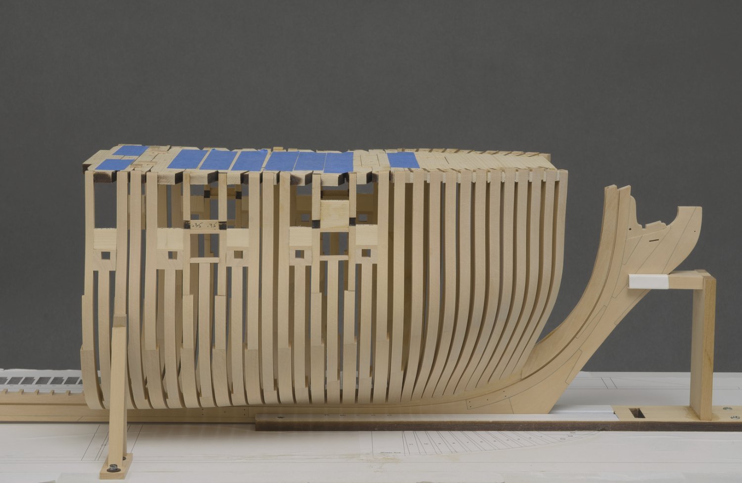
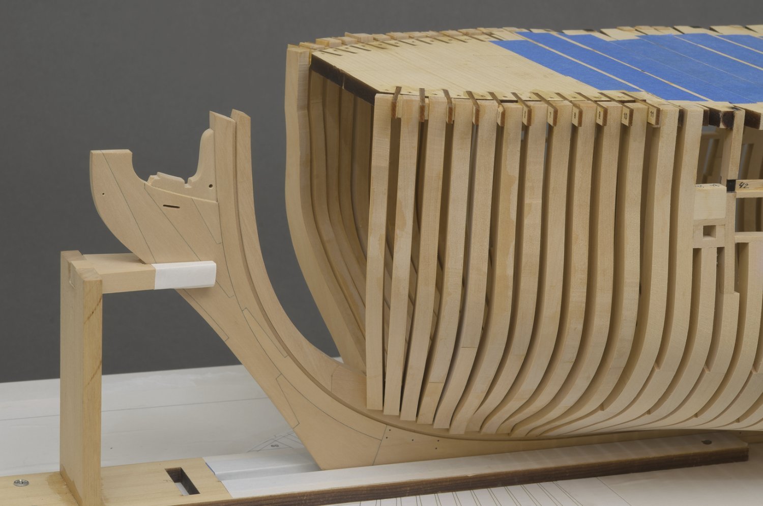
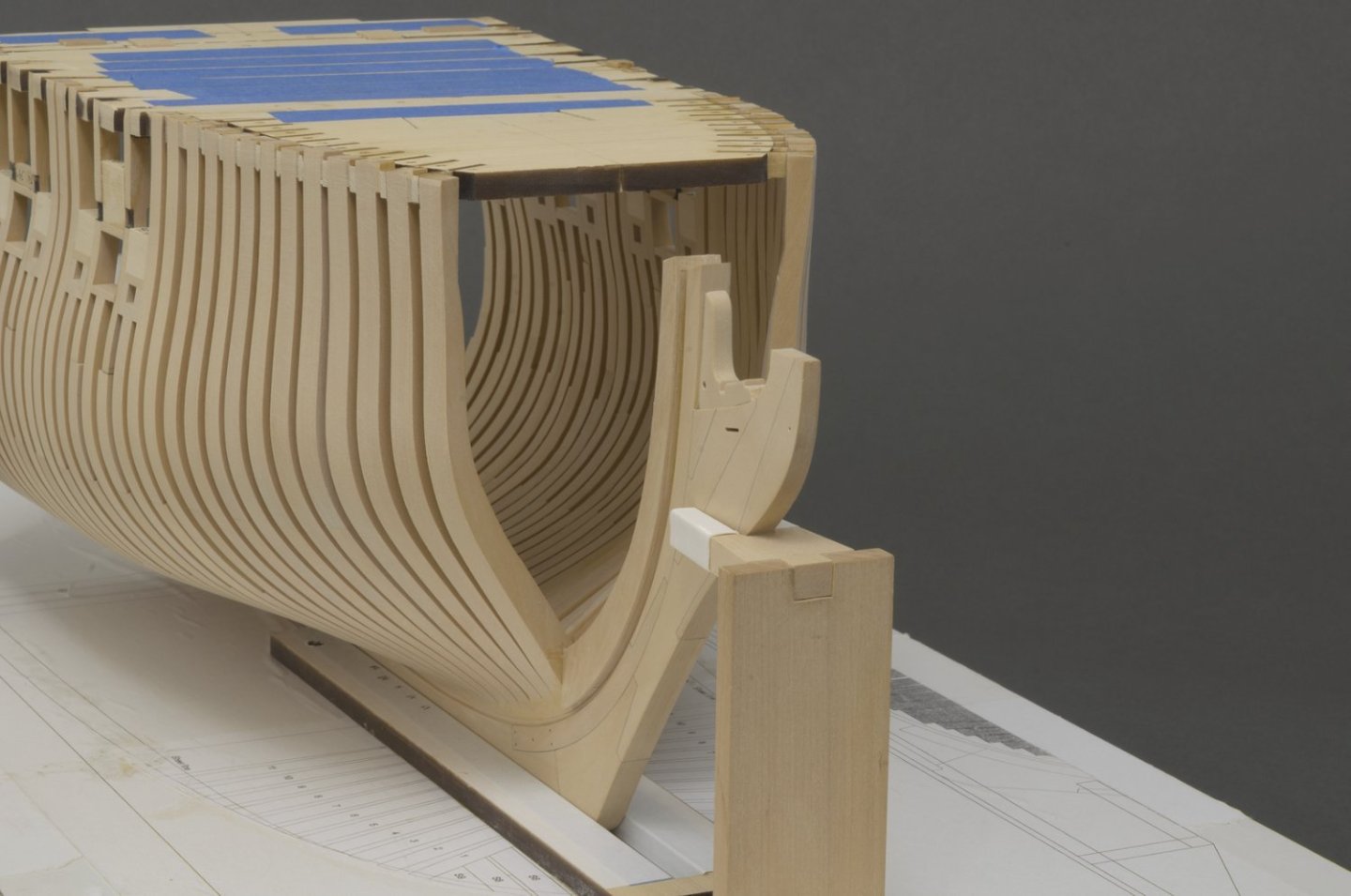
Adding the forward cant frames went rather quickly. Fairing them took me about three days, maybe more. Transitioning the deadwood into each cant frame had to be done carefully. I'm always finding the need to refine the previous fairing work after new frames are added, though less each time. I added the 3/64" P1 and P2 filler pieces to each side of the stem as well. Mike
-
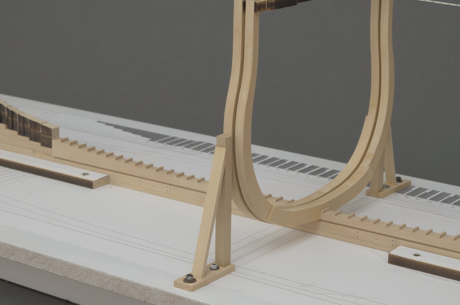
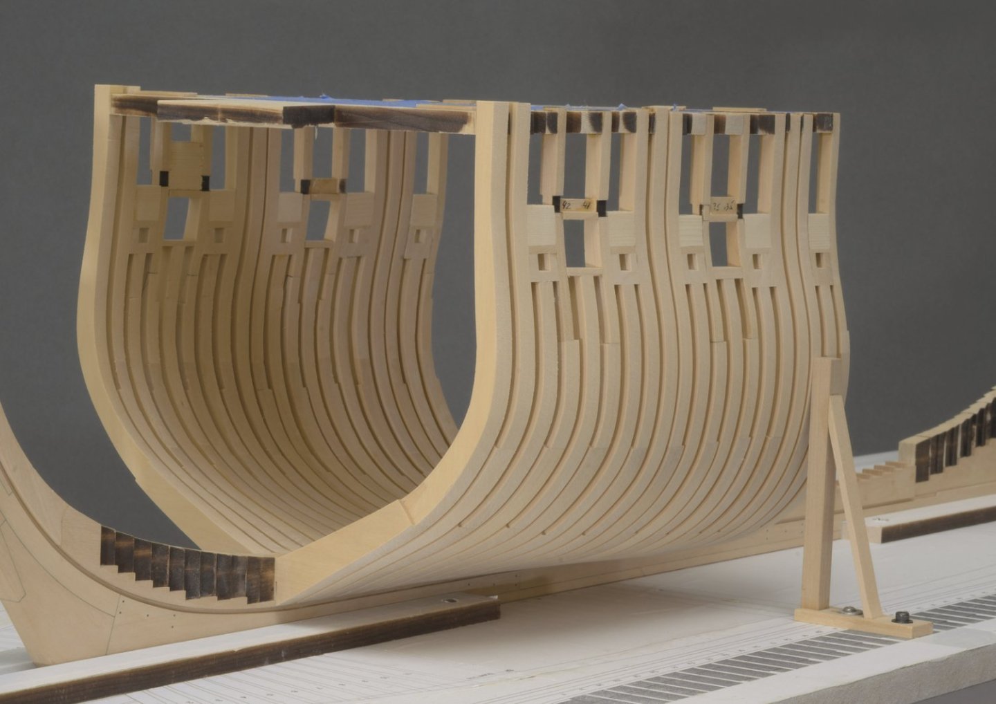
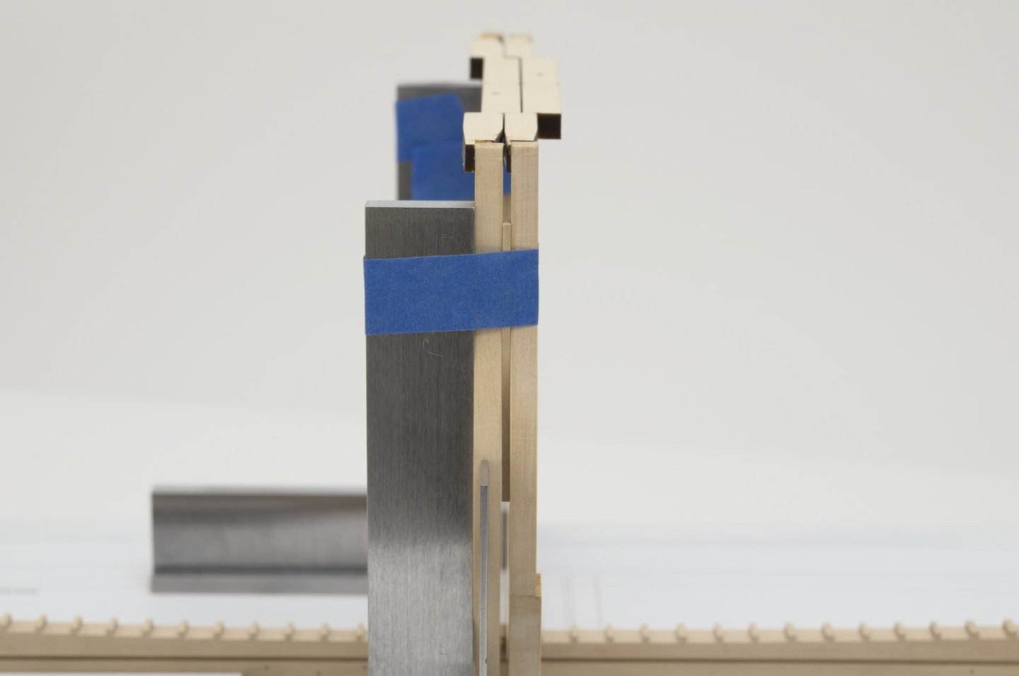
Keeping the cants vertical is really important. When the spacing started to get tight, I simply angled the machinist square to clear the frame already installed. A strip was used to hold the frame against the machinist square while the glue set. It was easy enough to get the right strip thickness by adding layers of painters tape. At the top of each frame, I added boxwood wedges to fill the gap between the frame and the numbered support strip. This ties everything together and should give a lot more support when fairing the cants. It's hard to see the true run of the cant footing since some of these cants are further away from the keel than others. Actually, the square frames where the same way, giving me the false impression that they would not fair in properly. I'm sure that things will work out okay for the cants as well. Mike
-
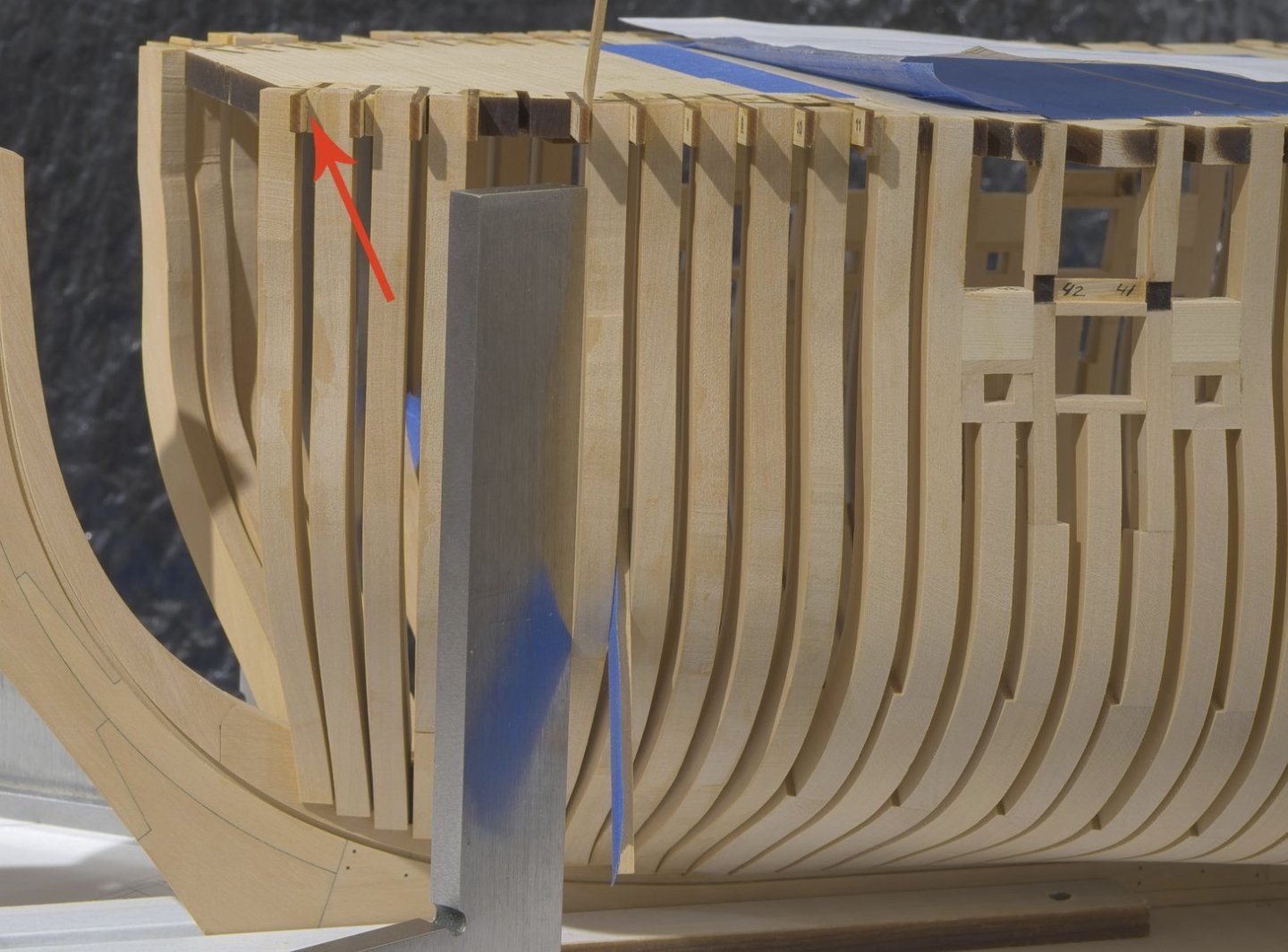
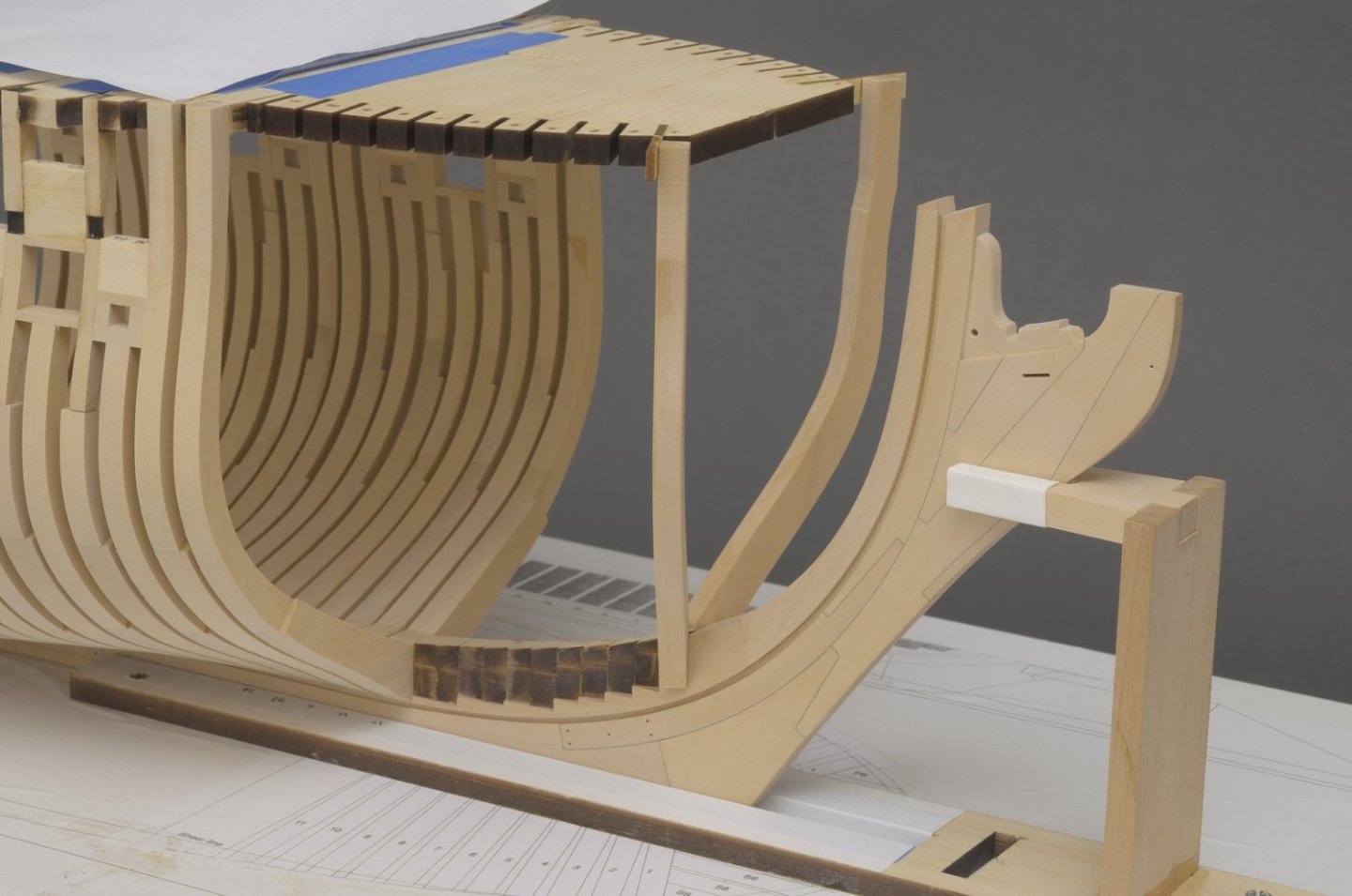
Cant frames (fore) Happy 4th everyone! 🎆 I started on the cant framing over the weekend. The first frames to go in are cant #1. They will also hold the front of the top jig in place. I made a slight adjustment to the foot of each cant in order to get a snug fit into the deadwood. While using a machinist square, I moved the frames outward a wee bit beyond the etched line on the strips in order to clear the bearding line. Not much, maybe 1/64" or even less. That was it. I was very surprised to see that the cants went in square to the build board. The paper template comes in handy as a double check on what you are doing. I actually prefer using it over just relying on the build board plan. The front of the template is at the aft edge of the rabbet as seen from above. Only ten more to go. Oh, yes I accidentally hit the top of the gammoning knee. Luckily it came off clean for easy replacement later on. Much later on! Mike

-
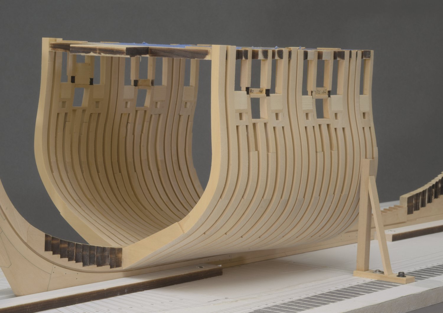
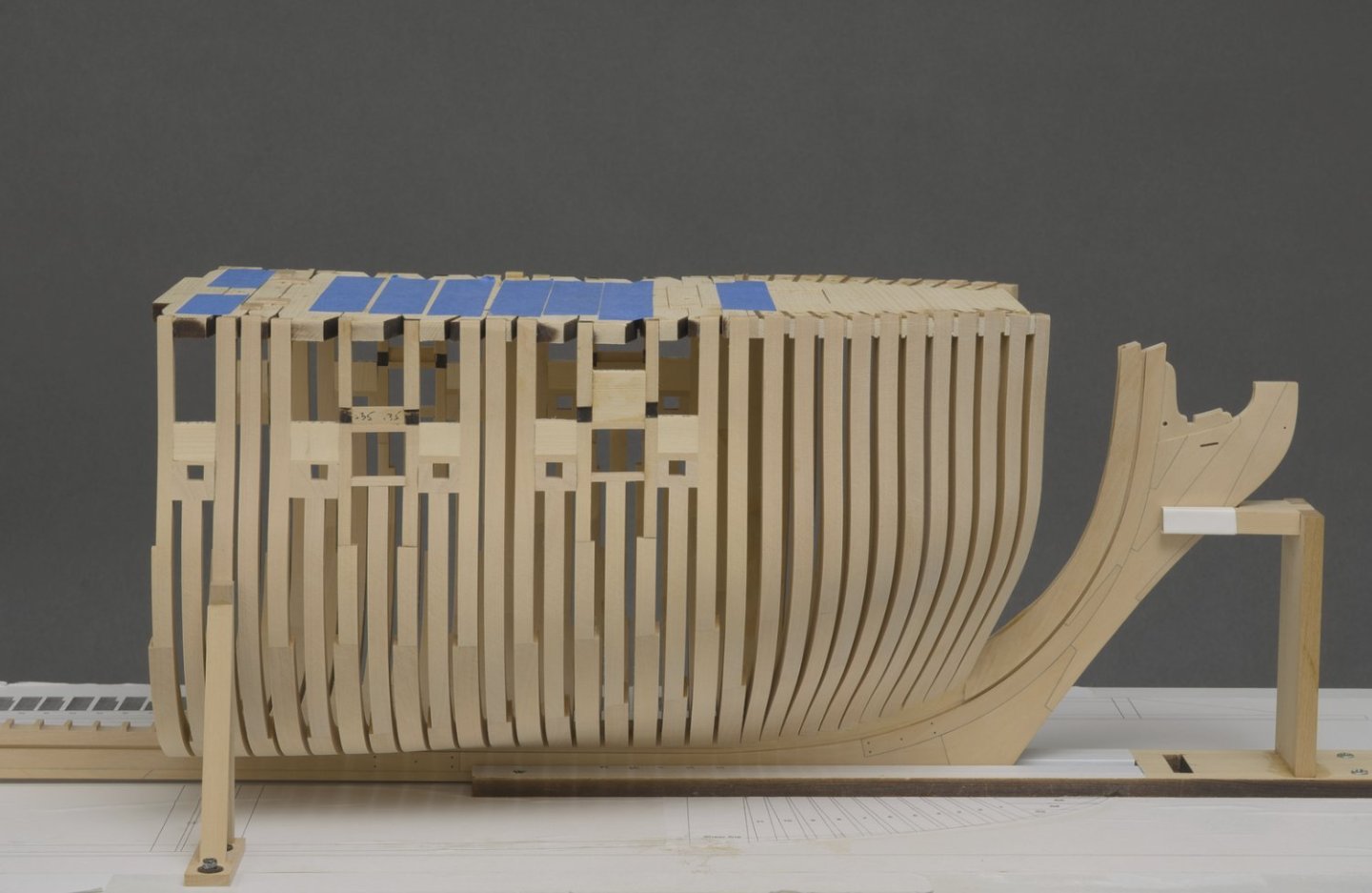
Hi guy's! A little over a month and 15 more frames added. Fairing continues after every 5-6 frames. I can't stress how important it is to fair as you go along. The hull shape is constantly changing, so the previously faired section needs additional work in order to match the newly faired section. Additional supports were added above the gun ports. Mike
-
Thanks, guys!
-
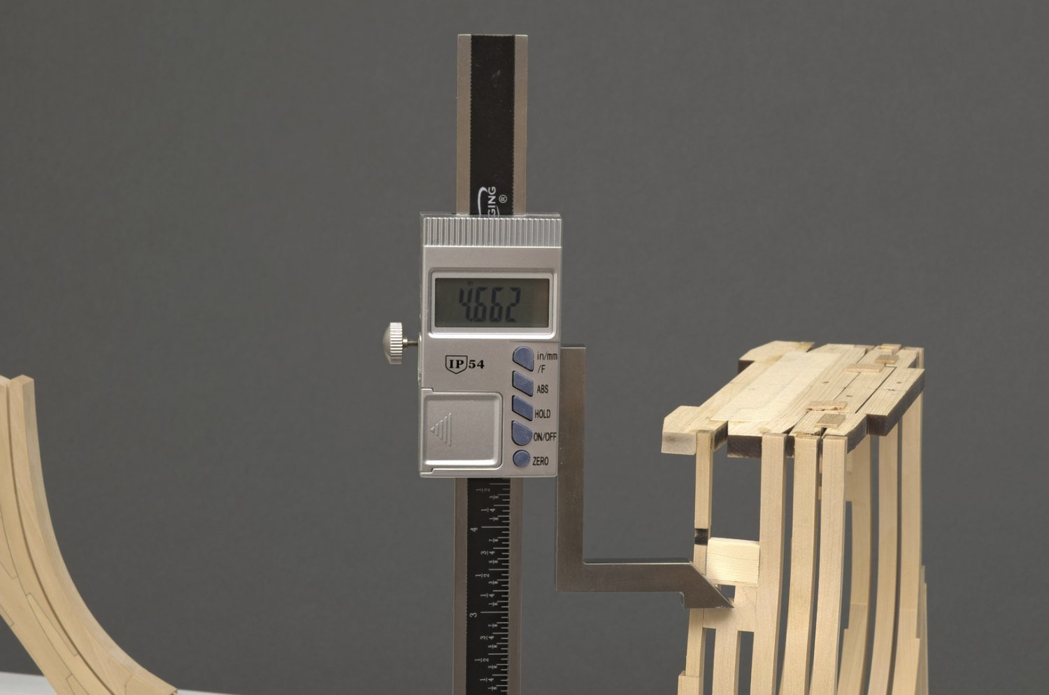
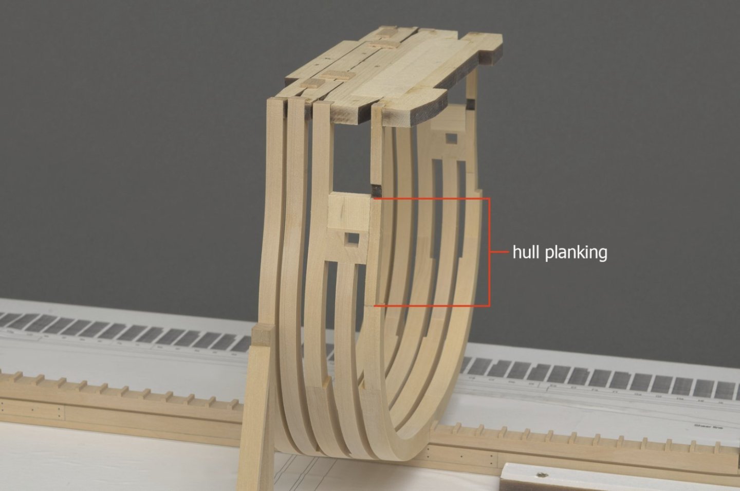
I now have five frames completed along with scratch built sweep ports. I added Yellow Cedar above the ports as filler pieces which extend to the sheer. To save some milling operations, that will be hidden later, I used Chuck's 5/32" laser cut top timbers. This nonuniform area will be covered up later with the upper hull planking. The five frames are mostly faired and the outer faces sanded close to the half breadth. Of course, there will be more work needed for final fairing which includes getting the sheer to a width of 5/32”. The height gauge makes it much easier to find the proper height of the sweep port. Measurements for this are taken directly from the plan. The 4.66" height is well within my .005" margin of error. I still need to reverse the tilt table on the mill in order to make it possible to do a scarph joint on one side of those long one piece floors. The setup doesn't take all that long to do, though I wouldn't want to make the change for every frame. With that in mind, I'm going to work the frames in larger groups rather than individually. Mike

-
Congratulations, Rusty! You have made a beautiful model with rich colors that anyone would be proud to display. have you come up with ideas of how you were going to display her? Mike
- 642 replies
-
- 3
-

-
- winchelsea
- Syren Ship Model Company
- (and 1 more)
-
Thanks, Chuck!
-
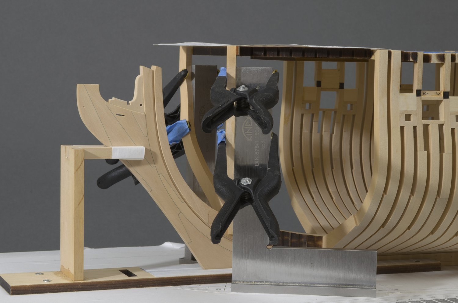
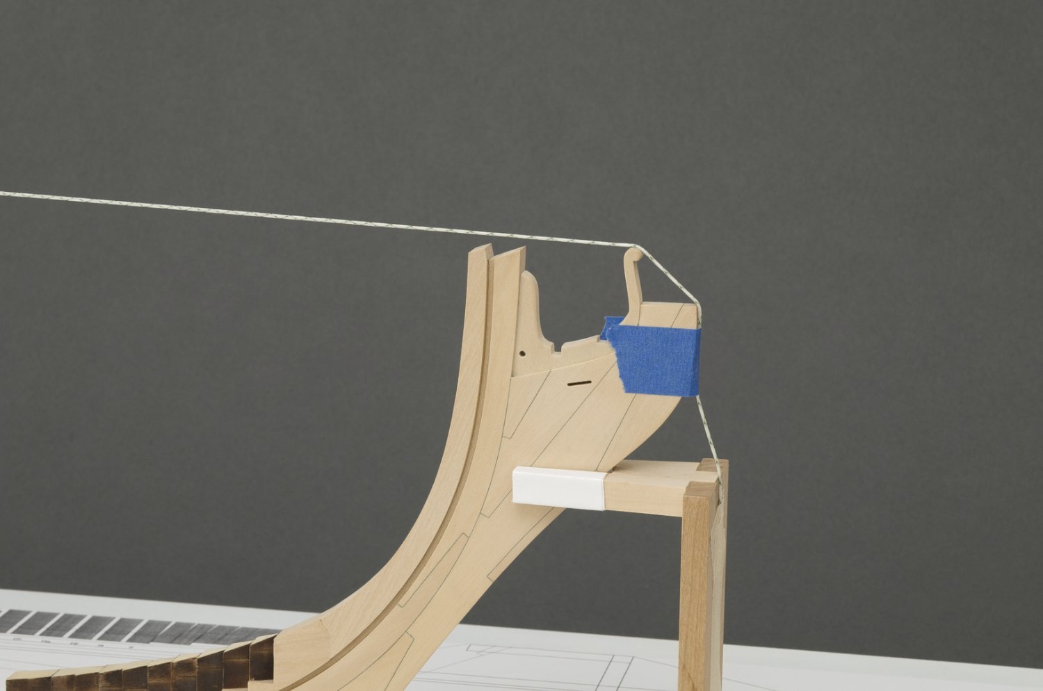
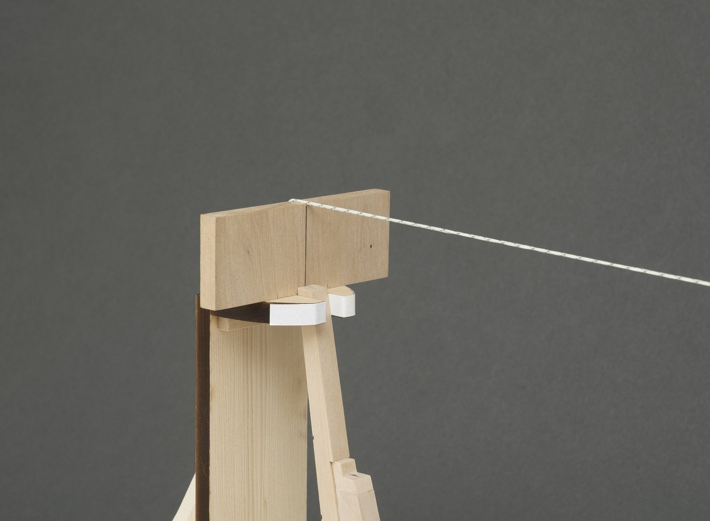
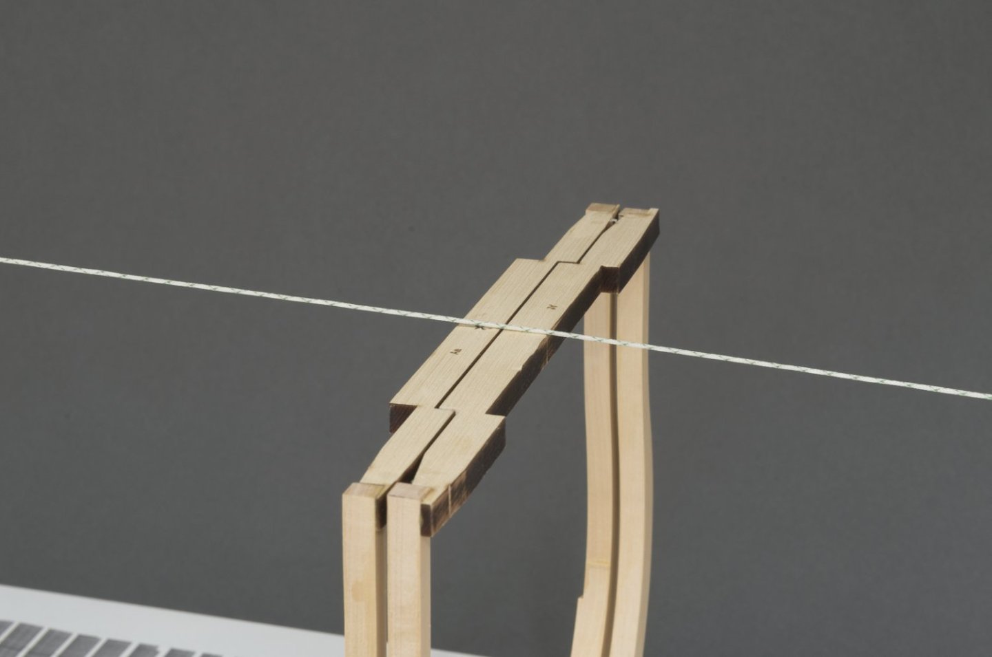
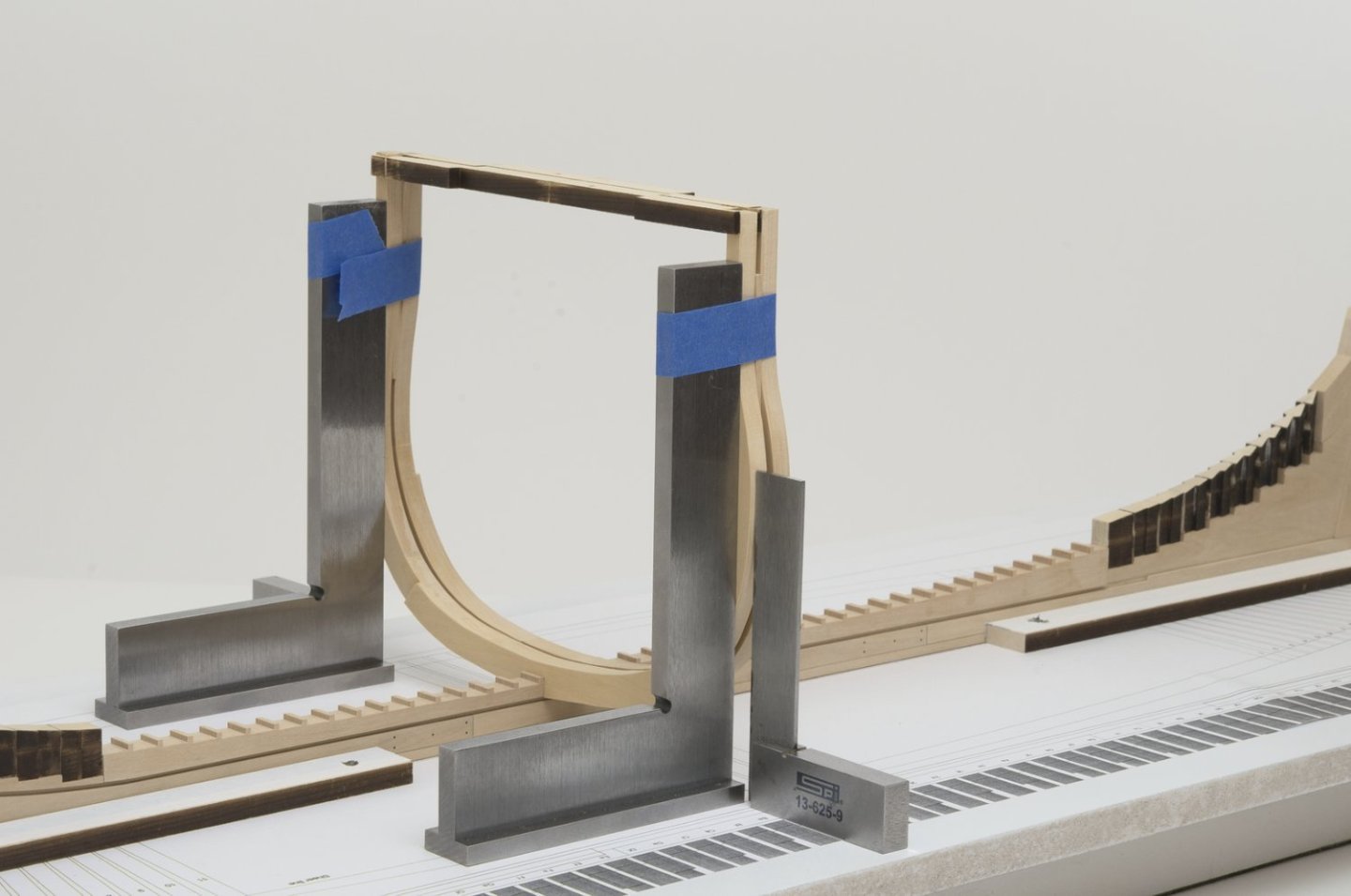
I will use the Aa frame as a reference for aligning the other square frames. It's important keep this frame from moving laterally while at the same time being centered with the stem and stern post. The first step was to come up with a way to hold the frame firmly in place. A low profile chock placed under the frame and against the build board was one option, but I wanted a more rigid solution. Using clamped machinist squares against the frame was not an option, since they would surely get in the way when working around the build board. The solution was to make two squares from some boxwood scrap. The bottom leg has milled slots which allows the squares to move in and out. 4-40 bolts and blind nuts would be used to hold the squares firmly in place. The next step was aligning the center of the frame with the stern post and stem. I ran a string between these two points. Due to the difference in height between the stem, stern post and frame tops the string angled in such a way as to create excess pressure against the frame top. When I snapped the string the centerline varied because the string couldn't move freely against the frame top. The fix was to glue a piece of wood to the top of the stern post jig. This straightened the string considerably while taking pressure off the frame top. The top edge was notched in order to hold the string on center while tension is applied. I used tape to hold the string along the top of the gammoning knee. Snapping the tightened string over the frame established an accurate centerline. The squares could now be moved a wee bit in or out to hold the frame centered and firmly in place. Mike


-
Hi guys! I've been patiently awaiting on a new shipment of wood from Hobbymill.eu. I mistakenly thought that I had enough 5/16" sheet for the frame floors. In an effort to keep the color match close to what I already have, I sent a sample to Vahur. He is working on it and as soon as I receive the new wood I will start posting again. Thanks again for your continued interest in my build Mike
-
Yes, Rusty. I totally agree. This is something I've been saying all along. Laser cutting is just the first step. Afterwards, much care is needed in order to get results like the ones seen in Chuck's builds. Care and Patience will always yield a better result.
-
Oh, I believe in yesterday. . . 🎵🎵🎵🎵🎵╡🎵╡
-
looking really nice, Rusty. Nice and slow.
- 642 replies
-
- 2
-
-
- winchelsea
- Syren Ship Model Company
- (and 1 more)
-
Thanks! Better to ask Chuck, he would know.
-
Gary, These are very stable, so they not to tip over easily. This is my go to company as well. Friendly staff and very good service. https://taytools.com/products/kinex-machinist-try-squares-with-base-875-1?variant=32402292539479
-
Tom, I trust the angle gauge. A scarph angle on the plan was 7°. I set the angle gauge to that after doing a horizontal cut. The 7° cut was right on the line that I was milling, for its entire length. When I joined the floor and futtock the frame shape matched the plan beautifully. I don't think that I could ask for more than that. Of course it would be nice if the angle gauge was digital, but I'm not complaining. Square Frames (pt.1) After getting acquainted with the new mill along with some trial and error with initial setup, I'm ready to move on. The first frame I installed was (Aa). The scroll saw, spindle sander and disc sander made shaping easy enough with minimal work required. I used PVA and some squares to hold everything in place while the glue dried overnight. The width of the frame lines up nicely with the half breadth line on the drawing with some wiggle room for fairing. In addition to the frame being vertical it is also square to the rising wood. I would not expect the laser cut frames and jigs to match perfectly with my milling work. I was curious as to what would happen when adding the second frame. It was very close but not exact. That didn't bother me at all. I knew that I wanted the frames to be parallel to one another, so I made a strip the same width as the space between the two frames. When setting the second frame I used the strips to ensure that the spacing was even between the frames. The space between the two top cross pieces is barely that of two sheets of paper or 0.010". I can certainly live with that and I much prefer that the view from the side is as even as possible. Once the glue dries and before I remove the squares, I will secure those top cross jigs together, . Mike
-
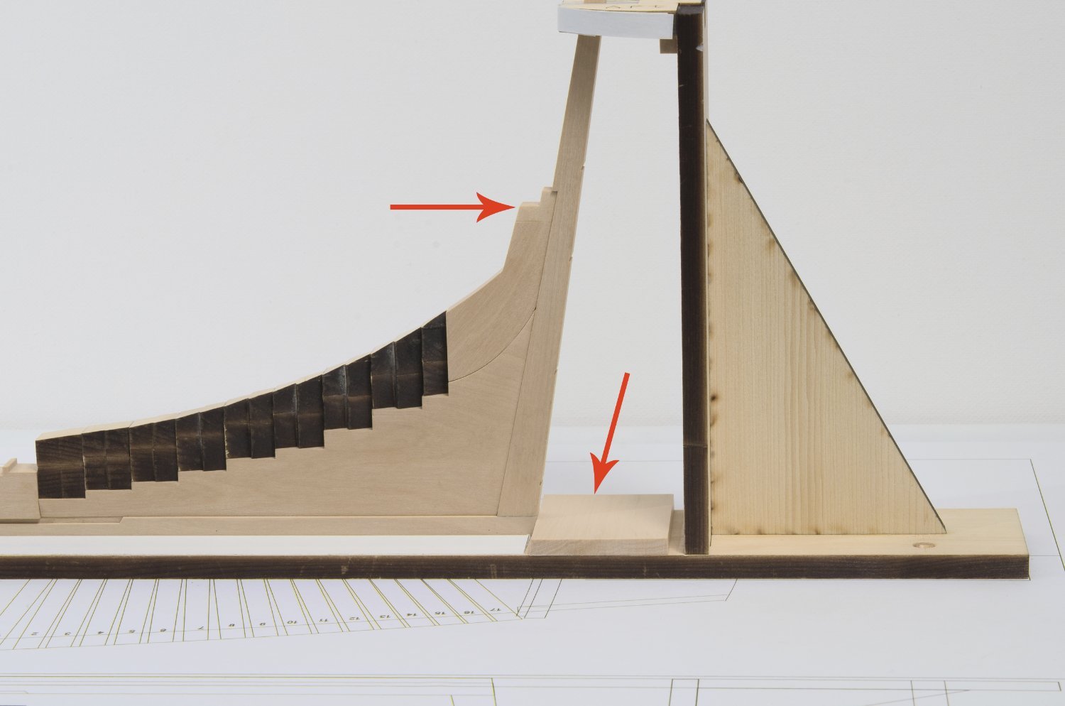
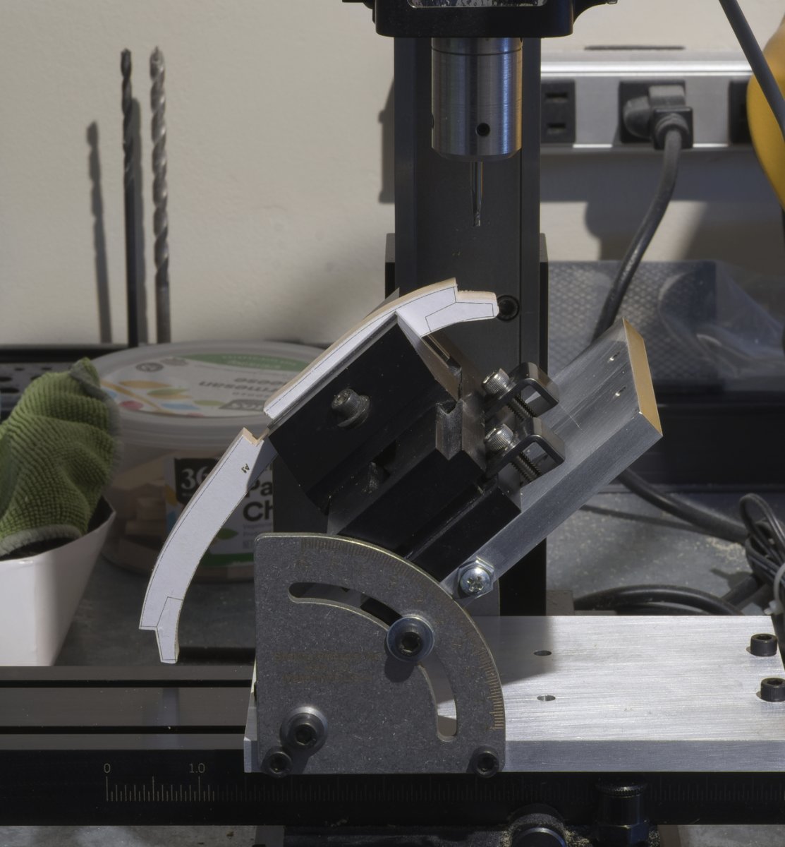
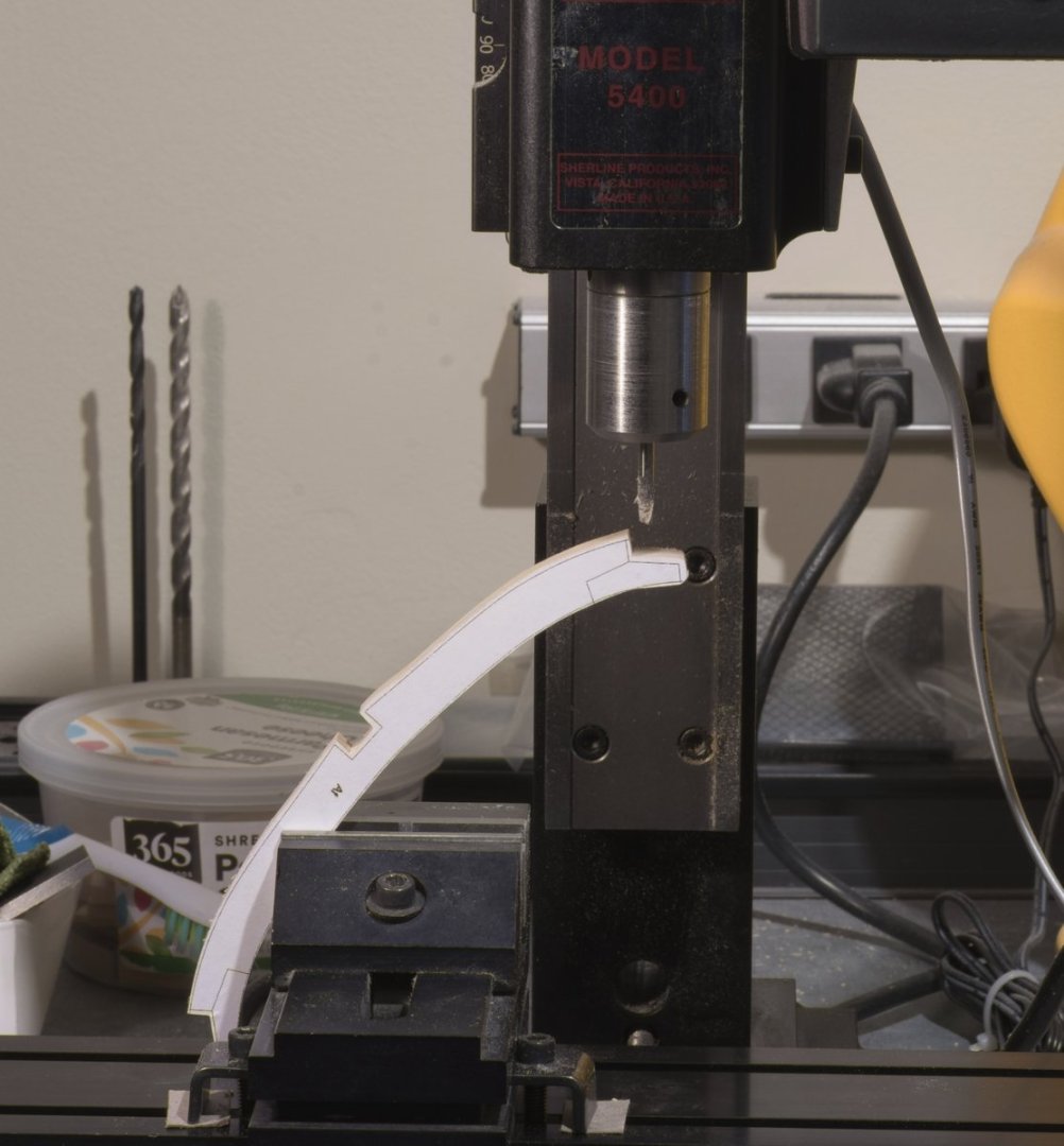
Moving along, I added the extension piece to the top of the rising wood. This establishes the proper height for the wing transom. While I was at it, I placed a stop behind the keel to register its exact position relative to the drawing. I made it to the same angle as the stern post to prevent any marring of the wood. Square Frames (initial setup) It wasn't long after I started to make the first frame that I realized I had a problem. At the larger scale some of the floors end up being quite long. In order for the end mill to cut the scarph joints cleanly the wood must be held firmly near the cut. Too much movement could result in chip out or even chunks of wood being torn away. As you can see here, the initial setup was far from being ideal. Being a newbie when it comes to milling, I reached out to both Mark and Greg for some expert advise and a little brainstorming. They were very helpful with their ideas and suggestions. In the end I went with a Sherline tilt table which is predrilled at the factory for attaching the milling vise. It has an angle gauge in one degree increments as well. Thanks, guys! Mike


-
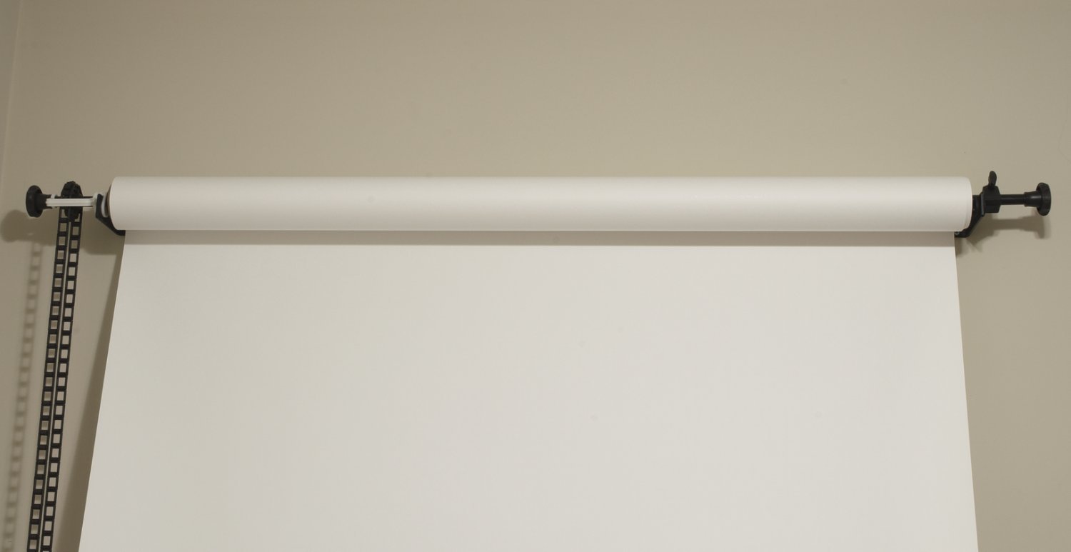
Glenn, My setup is quite simple. Just a white backdrop that is for the most part white balanced already. Also I shoot under an overhead ceiling fixture that has 3-5000K LED's. Sometimes I use an umbrella to reduce shadows. Here are a few links. HTH https://www.bhphotovideo.com/c/product/1732646-REG/neewer_66600016_1_roller_wall_mounting_manual.html https://www.bhphotovideo.com/c/product/1508549-REG/savage_1_5318_background_paper_super_white.html https://www.bhphotovideo.com/c/product/362385-REG/Impact_S3233_White_Translucent_Umbrella_33.html

-
Steve, you have done a great job on her so far. This is no time to walk away over one little section of the ship. Slow down, concentrate and get it right. You’ll be glad you did.
-
Jim, I think that Ken is referring to my build log.