


Beef Wellington
-
Posts
2,245 -
Joined
-
Last visited
Reputation Activity
-

 Beef Wellington reacted to Michael P in HMS Agamemnon 1781 by Michael P – scale 1:150 – 64-gun Third Rate - Ardent-class Man-of-War
Well, it's been some time since I added anything, as progress has been slow. Never fear - this build log won't be an incomplete one. I don't want to hurry, as there's not that much room in the house for yet another ship model.
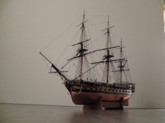
I've worked on the guns, as the photo shows. It seemed right to fit them now, as once the gangways are in place, it would be more difficult. In my teenage years I used to make the guns by casting them from lead, in moulds made of plaster of paris. To melt the metal, I used a gas ring attached to the gas fire in my bedroom, and for the lead, found disused pipes in the cellar. Not exactly advisable in health and safety terms, but it was the late 1950s. For this model, I have simply carved the cannon from wood dowel, which looks ok at this scale. I'm certainly not up to using a 3d printer, even if I had one. The cannon are all Blomefields, with the ring on the cascabel to take the breeching rope. This makes rigging them a good deal simpler that it would have been with the Armstrong type, though I imagine that in reality ships in the late eighteenth century had a mix of the two types. The rings were not that easy, but I ended up making them from paper. Rigging canons is a problem at this scale. The carriages all have wire loops on the side to take the breeching ropes, which helps, but the various tackles would be a problem. I may fit training tackles in time, but the blocks would have to be very tiny, and having just the breeching ropes at least gives some impression of the way guns were rigged.
The deck was straightforward, with the caulking done with a softish pencil. On this scale, the planks would have been about a foot wide, which is a bit too much, but they are at least a good deal narrower than is sometimes the case in models. They have had a coat of danish oil, while the gratings have had french polish.
Next, I think, will be the gangways etc., and further work on the stern.
-
Beef Wellington reacted to Sjors in USS Constitution by Sjors - Model Shipways - Scale 1:76
No update but something else
When i take a look at the other Conny’s ,there is a difference with mine.
I see parts that i can not find….
I have no deck so the planks are going on the frames and at the bow i’ll be missing some lasercut parts.
Anja has found why.
It’s a kit of 15 years old!
It’s semy scratch. 🥲
So more difficult for me but i still will do my best.
I hope to show you tomorrow a little progress.
The filler blocks at the stern and bow.
Sjors
-
Beef Wellington reacted to Sjors in USS Constitution by Sjors - Model Shipways - Scale 1:76
The false keel is together and the frames are in it
-
 Beef Wellington got a reaction from Old Collingwood in HMS Indefatigable 1794 by Kevin - Vanguard Models - 1:64 - Feb 2023
Looking great Kevin, nice paint job. When I first saw the pictures it looked like the upper hull was blue, but its clear that's just lighting!
-
.jpg.d84ec4dad1d7791e855dca06210ab6f3.thumb.jpg.f45209242e851d4409eca1a09293165b.jpg) Beef Wellington got a reaction from hollowneck in HMS Jason by Beef Wellington - Caldercraft - 1:64 - Artois-class frigate modified from HMS Diana 1794
Beef Wellington got a reaction from hollowneck in HMS Jason by Beef Wellington - Caldercraft - 1:64 - Artois-class frigate modified from HMS Diana 1794
The Ekeing and Cathead supporter:
The Ekeing is a detail as presented in the kit that consists of a simplified approach consisting of cat head supporter and ubiquitous white metal moldings. I was determined to make this as prototypical as I could as shown on the plans. Studying numerous contemporary models, this is a detail that seems to vary quite a lot, and I'm unsure whether this varied significantly from ship to ship, or whether the model builders took their own simplified approaches. The following photos of Minerva helped a lot in visualizing this complex shape consistent with the original plans (photos are my own taken at the Rogers Collection).
This was a very humbling experience and definitely one of the more challenging pieces to make, requiring many hours of fiddling and sanding. In short (!) , the Eking and cathead supporter needs to meet the following criteria:
Narrow from 3mm to approx 2mm at the middle rail to butt into it cleanly Follow the curve of the hull Extend the graceful curve of the middle rail up to the cathead when viewed from the side Be positioned such that the cathead sits snuggly against the top of the main rail, and is perpendicular to the hull Follow a smooth curve outboard from the cathead to the lower rail, the ekeing curving forward almost immediately below the cathead Pass just upward of the outboard hawse hole, but cross the inner....(differing from Minerva above)
I had a couple of abortive attempts which while failures, were very helpful in helping me understand the approach described in TFFM Vol 2. The best piece of advice here is focus on one curved face at a time. A cardboard template was made to approximate the profile (this was initially estimated using the spare metal molding strips which work well for this). (Note: In the photos below, the various rails have been cut out to allow placement of the final rail. (When the template was made this had not been done which made this a little more challenging and subject to approximation)
The profile of the hull at the bow was taken using a profile gauge and transferred to block of balsa. The ekeing template was transferred to some 5mm pear sheet and cut out leaving quite a bit of excess. The hull profile was then introduced onto the inward face. The shaped balsa block helped a lot in this exercise to allow frequent validation.
Once the inner profile had been finalised, the card template could be used to fine tune the shape. This has to be transferred onto the curved surface that will sit against the hull, and it important to remember that the profile on the outboard face will be different because the shape will follow perpendicular to the interior face (i.e. the hull). Some excess was still left here to allow additional fine tuning.
The top of the profile was then thickened using some more 5mm pear, and the cathead supporters roughly shaped and glued into place. The cathead supporters were attached perpendicular to interior face, not the exterior face. This rough structure can then be further fine tuned, again using the template on the inner surface and ensuring that the top and bottom face are perpendicular to this along its length. Following the advice in TFFM, The sternmost face was worked first, and once finalized, the inside curve was worked using the outside as a guide. Once these had been completed, the outboard curve following the underside of the cathead supporter was introduced.
The lower version shown below still required a lot of fine tuning on the model.
Once happy with the shape, the position on the model could be determined, and the decorative rails cut to allow the ekeing to sit flush against the hull. This was definitely a little nerve wracking and will require a little touch up when all is said and done. (The outer surface profiling was not introduced until after this work had all been done and position finalised - these still require some finishing as these photos embarrassingly highlight...) The end of the ekeing also needed to have the shape of the hawse hole introduced onto its lower edge to open that up.To allow the position to be determined, the catheads also needed to be madeup. The "cathead" decorations on the end was made from polymeric clay and followed the very nice original example originally on Trincomalee and other contemporary models - they look a little more acceptable at a distance! Not much else to comment on other than the dimensions and decoration were estimated from the original plans and inspired by contemporary models. These will get further attention in due course. The upper rail is still just pinned in place and will require the top to be shaped prior to final installation.
Overall, I'm very pleased with how this came together, the various lines seem to flow quite nicely when viewed from the side which was a goal entering into this. The plansheer, ekeing, catheads and upper rail are all still dry-fit at this stage....but think I can move forward with more confidence.
-
 Beef Wellington got a reaction from dunnock in HMS Diana 1794 by DaveBaxt - Caldercraft - 1:64
I think you'll find that gallery former is very oversized. Suggest determining the right size and then playing around with the various items to get the best compromize. I never used this part. There are going to be compromises needed between the plans, AOTS and even the original plans because none of them reconcile exactly. Playing with the PE quarter gallery lights may also help you get a better sense of the final visual proportions. Good luck!
-
Beef Wellington reacted to Kevin in HMS Indefatigable 1794 by Kevin - Vanguard Models - 1:64 - Feb 2023
now to do it all again on the other side
-
Beef Wellington reacted to yvesvidal in HMS Bellona by yvesvidal - CAF Model - 1:48
I have completed the railing of the poop deck. Overall, it is quite delicate due to the length of the stands, and the long ones must be pinned if you intend to have something that holds correctly. The pins are made with electronic components pins of about 0.8 mm diameter.
Moving to the other side:
The parts provided in the kit require some adjustment in length and angles.
Overall view of the poop deck:
I am now going to work on finishing the taffrail and the stern flag pole. I may even attempt the assembly of the lantern....
Yves
-
Beef Wellington reacted to Sjors in Duyfken by Sjors - Kolderstok - scale 1:50 - VOC reconnaissance yacht
Don’t hunt Jason 😄
Just ask for me……
See my comment at Martin above.
I will make a build log for the Constitution.
Sjors.
-
 Beef Wellington got a reaction from Sjors in Duyfken by Sjors - Kolderstok - scale 1:50 - VOC reconnaissance yacht
Ah-ha, been hunting high and low for you....and finally found you! This looks like a very nice kit, and a pleasant change to the usual. Looking forward to seeing more progress, looks like you're off to a great start.
-
Beef Wellington reacted to Sjors in Duyfken by Sjors - Kolderstok - scale 1:50 - VOC reconnaissance yacht
I just told you that it is a slow build.
After two tuesdays of building at the club, all the frames are done 🙂
I think I have to build more instead of watching other projects and not so much talking
Sjors
-
 Beef Wellington got a reaction from Obormotov in HMS Indefatigable 1794 by Kevin - Vanguard Models - 1:64 - Feb 2023
Looking great Kevin, nice paint job. When I first saw the pictures it looked like the upper hull was blue, but its clear that's just lighting!
-
Beef Wellington reacted to Blue Ensign in HMS Indefatigable 1794 by Blue Ensign - FINISHED - Vanguard Models - 1:64 scale
Post Forty-four
The first Band.
I am using fairly scale lengths with a 140mm maximum and around 45mm minimum lengths.
1219
I am not going for a set sequence of repeat patterns, but I am giving mind to the positions of butts on adjacent strakes.
For deck planking I will take a more structured approach.
1224
I plank side and side about, and Ca is used throughout, with a pot of Acetone handy for wiping excess from plank faces as I go along.
1251
The required shape for the bow timbers is transferred to the planks, which are dampened, tapered, edge bent, bevelled, and generally fettled to fit.
I found this necessary from around Bulkhead five to the stem.
1231
1253
One of the advantages of the Indy hull is that apart from the bow area there are long sections of using full width planks which proceeds quite quickly.
1247
Looking a bit rough at this stage, but I now need to re-mark the hull for the next band of planking.
Onwards….
B.E.
01/07/2023
-
Beef Wellington reacted to KarenM in HMS SUSSEX by KarenM - FINISHED - 1:48
I drew the decor on a computer, then cut it out on a cnc machine. Then I finished it by hand.
-
Beef Wellington reacted to KarenM in HMS SUSSEX by KarenM - FINISHED - 1:48
I put the guns on the deck, now I can sew it up with boards
-
Beef Wellington reacted to KarenM in HMS SUSSEX by KarenM - FINISHED - 1:48
I cover with oil inside and out to the same level.
-
Beef Wellington reacted to Kevin in HMS Indefatigable 1794 by Kevin - Vanguard Models - 1:64 - Feb 2023
good evening everyone
Day 122-3 still coppering
im sure most of you would have completed both sides by now, i have lots going on, in RL but daily progress is being made
-
Beef Wellington reacted to DaveBaxt in HMS Diana 1794 by DaveBaxt - Caldercraft - 1:64
Thank you Jason and Allan for you help in the problems with the quarter galleries and wales , It seems to me that every time I deviate from the Caldercraft drawing and use other means there are consequences further down the line. As I wasn't happy with the quarter galleries where they meet with the top of the wales, I decided to check the position of the top of wales against the Caldercraft plans ( heights above the keel at each gun port) there are some discrepencees between this and the distance below each gun port taken from the AOTS book. It is my belief that as I altered the height of the gun ports to ensure that the Bloomfield cannon would be central in the gun port , I may have changed the position of the top plank of the wale, when taking measurements from the gun port. I therefore decided to use the measurement from the keel at each gun port from the Caldercraft plans instead of from the bottom of the gun ports ( measured from the AOTS Diana). Interestingy enough this has not altered the height of the wale of any significance at the stem and stern. For what it is worth I decided to remove the original first planks of the wale and re position them( using new ones) and taking the measurement from the keel and hopefully this will give the lines a better look.
Jason your idea of the quarter galleries in the kit being too big is definately worth exploring and may be the answer I have been looking for. Allen the problem with the counter is not that it bends too far as bending it further would move the quarter gallery further forward and then would end up too close to the last quarter deck gun port. If anything I thought about extendng the frame to move the stern counter further aft if anything but think that is a bit drastic. Allan I am pleased you posted those drawings as it does look like the supplied stern galleries are way too big. I will need to check these sizes with the AOTS book sizes as I am unsure how to take the sizes from RMG Diana and see where I am with this.
I would like to thank you guys again for your help and guidence as it is helping me a great deal. I would also like to thank everyone else for all the likes as this is encouraging me to keep going.
Here is what I hope is the final position of the wale . These are the 1mm walnut planks which sit under the final layer of planks. I will probably use walnut for the wale as this will be painted black.
-
Beef Wellington reacted to Mark P in Gun Port Hatches
Good Evening Gentlemen;
I am going to put a cat among the pigeons here, as I do not believe for one moment that the ports were separately lined with timber to form a rebate. For modelling purposes, this may be the easiest method to construct such a rebate, but in full-size practice this would entail a great deal of work, for no practical return. It is much easier simply to stop the outer planking short of the gunport, with the resulting exposed part of the main timbers of the hull frame, and of the inserted cills at the bottom of the port, forming the surface against which the closed port-lid would rest.
(Allan, thank you for your pictures above; but they only show that a rebate was present, and do not in any way provide an illustration of how it was actually formed physically in the ship)
The framing plan of Vengeance, a 74 of 1774 (available on Wikimedia Commons at high resolution) shows the timbers forming the gunports quite clearly, and on the lower deck the gun-port opening between the timbers scales at 3'4"; and for the upper deck ports it is 2'10". Furthermore, in places the timbers forming the side of the port are shown actually reduced slightly in width, as compared to the width of the same timber below the port cill, in order to increase the width of the port to the desired size. It is, in my opinion, very unlikely that the timber would be trimmed back, only to be later replaced with a separate piece of plank nailed to the side of it in order to replace that which had already been taken away. Just about every contract ever written at this period specifies a minimum for how much timber is to be left to the sides of the ports when the timbers are cut back to obtain the desired width of opening; so obviously trimming back the main timbers to give a desired opening width was common practice.
The 1745 establishment gives the gun deck ports of 70 & 80 gun ships a width of 3'5" & those of the upper deck either 2'9"or 2'10". At a later date, for a 74 gun ship, Steel gives a width of 3'5" and the shipbuilder's repository 3'6". For the upper deck they give widths of 2'11" & 2'10" respectively. In other words, the distance shown between the timbers on the framing plan of the Vengeance matches the given dimensions for the width of the gunports. So there is no room for any additional planking to be fitted to the side of the gunport openings.
The Shipbuilder's Repository also gives a dimension for the port stops of 3 1/2" for the gun deck ports of a 74. This is the distance by which the outer planking stops short of the side of the timber forming the side of the port opening. The author also gives a size for a 'lining' of 1 1/4"; this is given under the heading of 'Port Lids', NOT gunports, and refers to the thickness of the vertical planks which were fitted to the inside face of the horizontal outer planking of the gunport lids, this inner lining being sized to fit between the timbers at the sides of the ports.
The cover illustration by Ross Watton, for Peter Goodwin's book, 'Sailing Man of War', which is based on a model of Bellona in frame, shows this concept very well. Below is a sketch I made some time ago to illustrate the point made above.
Gun port details001.pdf
All the best,
Mark P
-
Beef Wellington reacted to DaveBaxt in HMS Diana 1794 by DaveBaxt - Caldercraft - 1:64
Before adding anymore planks to the wale I decided to make up a few of the parts for the quarter lights and see how they line up with the aft end and line up with the gun ports etc
Although this is just a rough idea what goes where, something is not quite right. With the stern counter in what I think is the correct position, the windows just in line above the floor and the top of the counter lining up with the upper bulwarks . The quarter lights look to be too high but follow the line of the deck. In this position the whole thing appears to miss the upper and lower gun ports which is mainly what I am pleased about . Unfortunately there is a probllem with the bottom of the quarter light housing and it looks as though I will need to lower the stern end of the wale so that only the bottom cast fitting just rests on the wale. I think this is the correct position for it but could be wrong.
I still need to add a few parts to the quarter light housing but unsure what I have done wrong as I was fairly confident that the wale was in the correct position but will have to check again. Any ideas where I might be going wrong with this and thank you again for your help and patience. Best regards Dave
-
Beef Wellington got a reaction from dunnock in HMS Diana 1794 by DaveBaxt - Caldercraft - 1:64
Looking very nice David, think all these small details, although somewhat obscured, make for a much more satisfying result.
-
Beef Wellington reacted to alross2 in OREGON on display
OREGON is now in its case and on display in the gallery. If you're in the area, stop in and take a look.
-
Beef Wellington reacted to Blue Ensign in HMS Indefatigable 1794 by Blue Ensign - FINISHED - Vanguard Models - 1:64 scale
Post Forty-three
The Preparation
I have (26) 5mm planks at midships which are marked off on the hull using a tick strip.
I intend to work a first band of six strakes below the existing planking, and I’m looking to have the plank ends at the stem not less than 3mm in width.
With this in mind, I apply the lining tape.
1173
1179
The first application of the tape, now the tweaking begins.
In these shots the upper tape marks the line of the first section.
I am aiming to get a smooth sweep up to the stem using edge bent and tapered strips only. I hope to avoid the need for spiling except perhaps when I reach the under belly of the hull.
The trouble with lining off is deciding when it is at its optimum line.
This process is more art than arithmetic and I find myself in an agony of indecision wondering whether I have reached that point.
Using strip wood there is inevitably error creep strake upon strake, so I will fit the first section and then recalculate.
The following photos show the point where I think I am getting close to an acceptable run.
1191
1193
1195
1199
1212
1205
1207
1203a
I think it needs a slight tweak as indicated.
1216
This looks better to my eye.
I can now proceed to mark off the strake widths at each bulkhead point and begin planking.
B.E.
27/06/2023.
-
 Beef Wellington got a reaction from AJohnson in HMS Diana 1794 by DaveBaxt - Caldercraft - 1:64
Looking very nice David, think all these small details, although somewhat obscured, make for a much more satisfying result.
-
 Beef Wellington got a reaction from DaveBaxt in HMS Diana 1794 by DaveBaxt - Caldercraft - 1:64
Looking very nice David, think all these small details, although somewhat obscured, make for a much more satisfying result.