lambsbk
-
Posts
910 -
Joined
-
Last visited
Content Type
Profiles
Forums
Gallery
Events
Everything posted by lambsbk
-
For those of you interested I started a separate thread to describe how I made the lanterns. It is still a thread in progress and I hope to finish it over the next week. Check it out if you are interested. http://modelshipworld.com/index.php?/topic/3163-fiber-optic-lanterns-ca-1845-196/
-
JCF: What can I say...when you're right you're right. Henry: next time you are on board you might want to get those sailors to make her ship shape. :) Thanks for the kudos on the hooks. It is still very much a work in progress. Dave
-
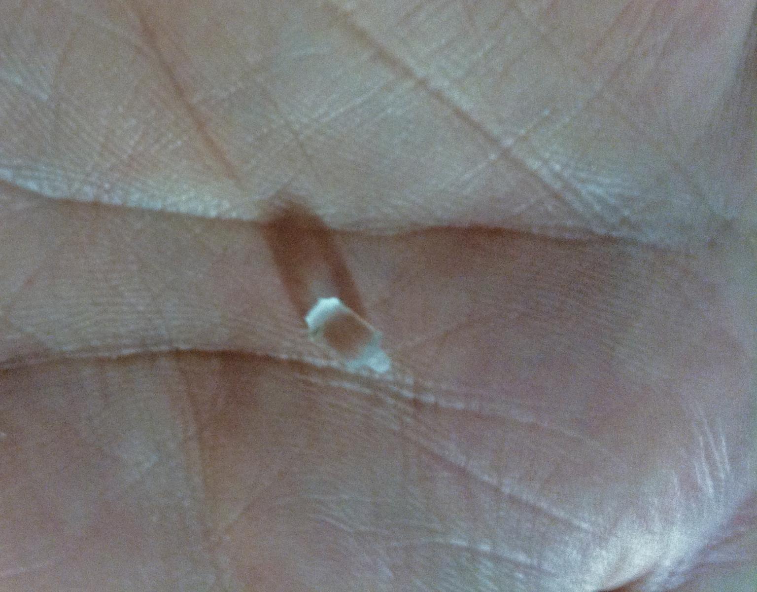
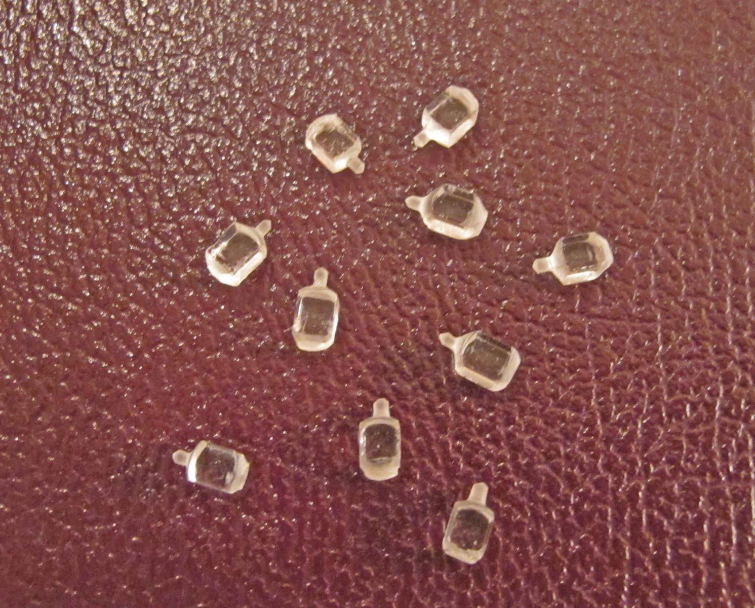
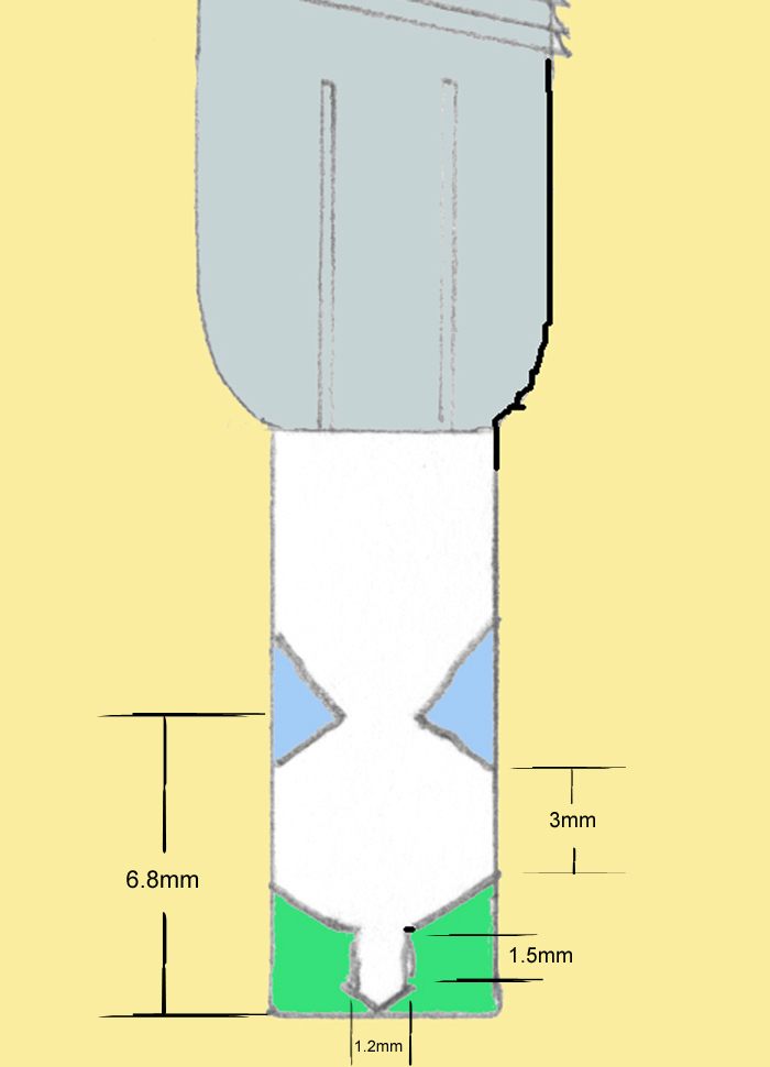
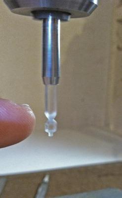
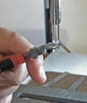
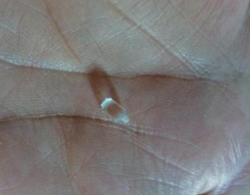
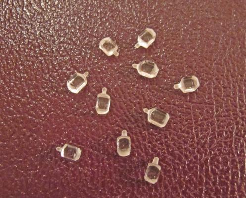
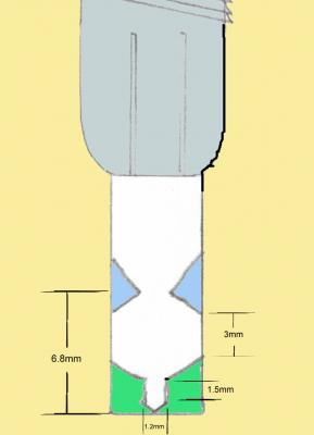
Next work out the blue shaded area working toward the scored mark. Once this area is worked with the file use the fine sanding stick (item 5) to lightly smooth the cut areas Stop the drill press once the base of the lantern is cleared and snip it off a little higher than you need for the lantern. Remove the pin vise chuck and discard the left over material (or save it for other uses - jigs, etc.) You may need to pull hard to remove the stock. In fact, I used vise grips a couple of times. Be careful not to damage the pin vise chuck though. Do some final fine file shaping and smooth the base flat. And it should look something like this. Total lamp length should be 6.8mm. This one is a little on the long side. I suppose I am a little out of practice. Expect that until you get the feel for shaping the plastic at this scale. After 2 or 3 you will be turning them out like the next pic. And after you have worked a few they will start looking like this...Some of these are better than others. You should make a few more than you need so you can reject the ones that won't work as well for you. I spent about 10 minutes shaping each item and about 5 minutes centering them in the chuck. Next up...how to drill them and finalize them.
-
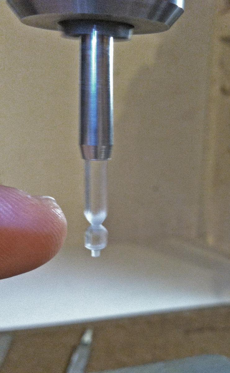
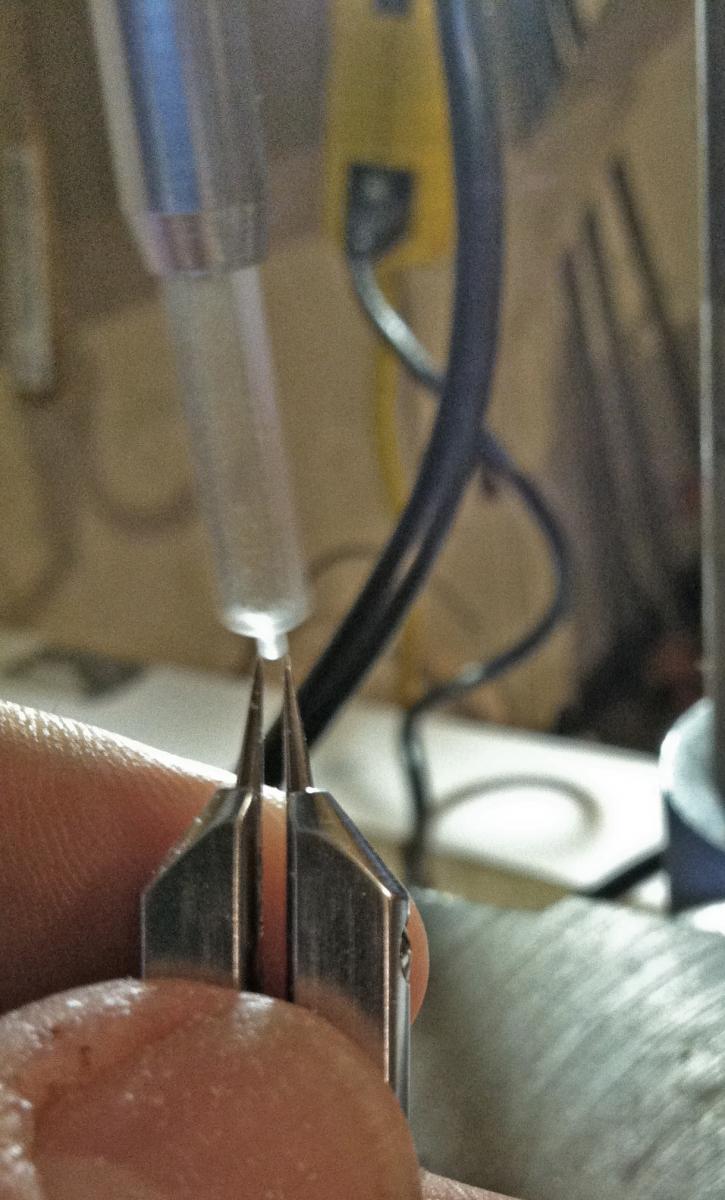
Here are a few pics to replace a thousand words. The file loves to jump up the lantern while lathing...hold it firmly but with light pressure to the plastic stock This shows the caliper measuring the cap length set to 1.5mm while the drill is turning. Measuring cap width at 1.2mm This pic shows the body of the lamp. It is 3mm. I marked it using the calipers while the drill was turning and it scores the plastic to show the next area to work.


-
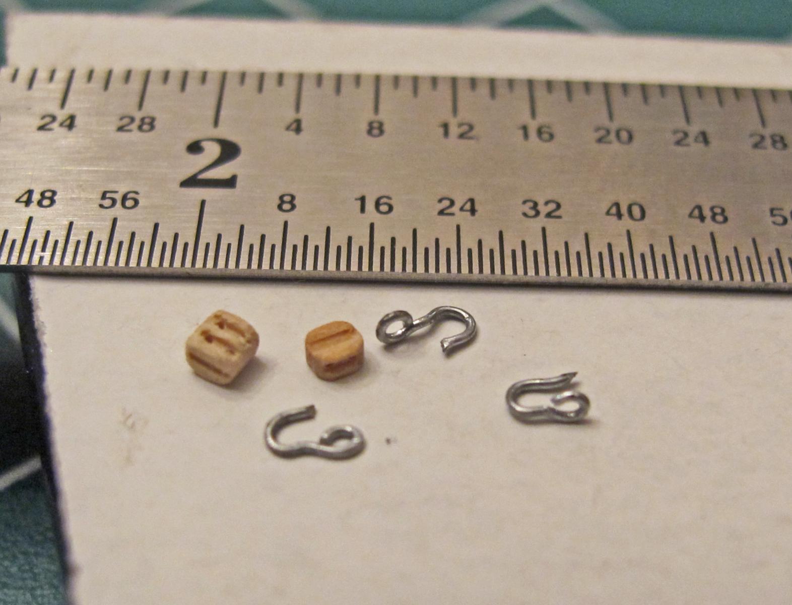
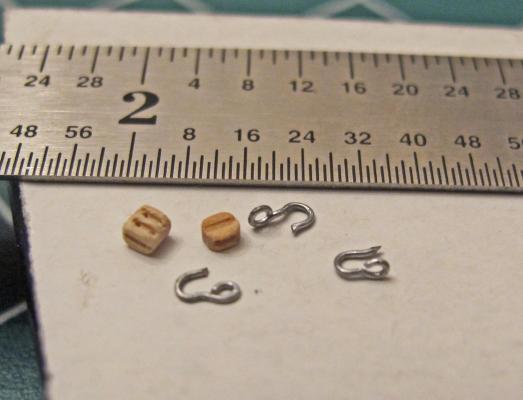
I see your point Chuck. The becket is going to be tricky (if not impossible - oh not for 1 or 2 - but after 56 of them I'll probably be bonkers). Anyway, here are a few of the hooks - fresh off the press so to speak - in the different styles (i.e. parallel/perpendicular/etc.). I have definitely not hit a stride yet.
-
Looks very good Verne. Just a question: have you thought about the port door tackle and where it will be going? Your current configuration would probably allow you to more accurately place it above the canon and between the knees. Really nice. Keep up the good work. Dave
-
Next 'lathe' the piece to specs. You'll need the calipers (1) and an accurate ruler**(12) to accomplish this. First the green shaded area will be worked down followed by the blue shaded area. Don't take too much off at once. Let the piece ease into shape giving it some cool down. The best way to describe the technique I think is to treat it like your brakes going down a long hill or mountain: hold it down for a bit then ease up, repeat. **I never really paid much attention to the accuracy of rulers until I used one which continued to give me inaccurate results - when I compared it to 2 others it was 5% SHORTER than the other 2!
-
Oh. And of course it took 2 or 3 coats of paint to do it. I probably should look for a cheap air brush. I think the off-white interior will look good if it can be visualized after the Spar deck is placed (my burdensome hope after working these details into the deck).
-
Len: I agree. Actually I have been practicing making these perpendicular hooks and I believe they are a little easier than parallel hooks. It is easier to grab the eye while working the hook end. Once I get some reproducibility in my technique I'll post some pics. Thanks for the info. Also, the tree nips I have been using (beader's snips) are awful at cutting the hook. I am going to try a nice pair of nail clippers tonight. We'll see... Dave
-
Thanks for sharing the info Verne. I wondered how they did that. I would have never thought of using the roots. Dave
-
I did paint the 'floor' of the gun deck (I think that is what they called the ceiling of the Spar deck) the same off-white (homemade antique white) color of the bulwark. The 'extra' eyebolts came from the second kit. I probably would have had enough from the first kit since Andymech and others have warned about making (from wire) or replacing the plastic eyebolts for METAL ones in areas where strength is needed. I plan on following their sage advice and that leaves you with extra plastic ones (how many extra ones I do not know - yet)
-
Dan: I think your replacement windows look great. Dave
-
YoungTiger and wedge thanks for the kudos...and Torrens. What a nice complement from such talented folks. Rick: you are right on the eyebolts. The eyebolts are placed 90 degrees to the bulwark. In those cases I did drill through. In fact, to get them even with the waterways I drilled from the outside! (I definitely used the Dremel for these steps.)The eyebolt stem then filled in the gap of the drilled hole when glued from the inside. The actual bolts do run through and through the bulwark of the ship however and so the effect actually enhanced the look. I used a little green modelers putty to fill a few of the gaps and it dried to look like copper rust. That was just good luck though. The ring bolts are drilled from the inside at 45 degrees to the bulwark. I modified some eyebolts by heating the stems gently and bending them 90 degrees into a hook like form.Then they just hang from the drilled hole and glue secures them. That gives me the luxury of pre-rigging the breeching to the eyebolts before attaching it to the bulwark. I hope that helps...I'll try to get some pics of these steps later. Dave
-
Augie...the bar keeps raising up here...
-
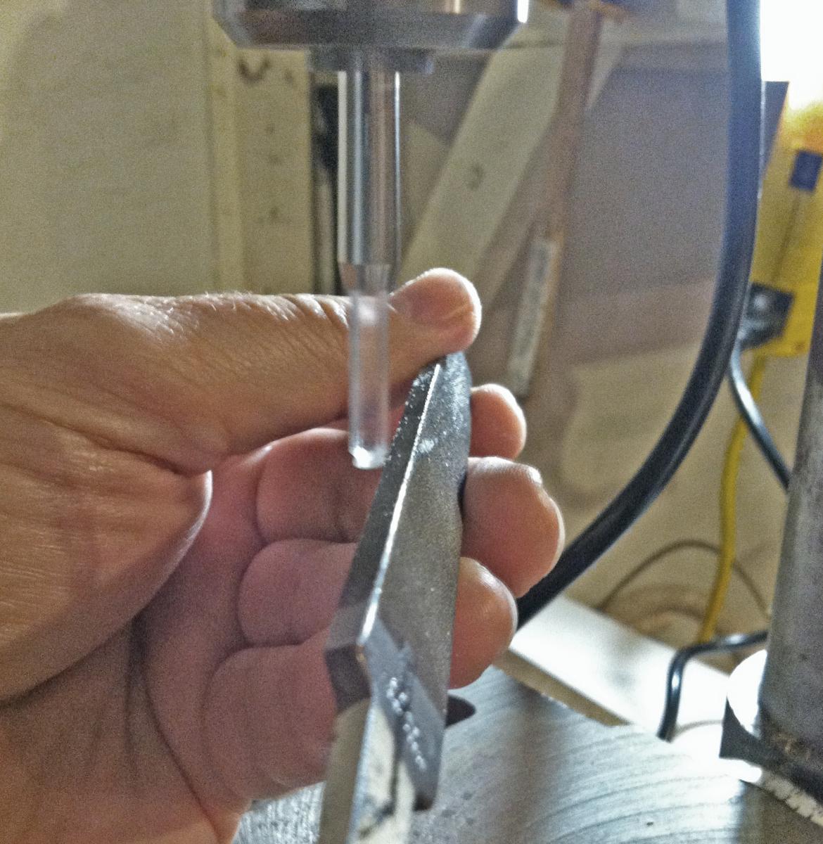
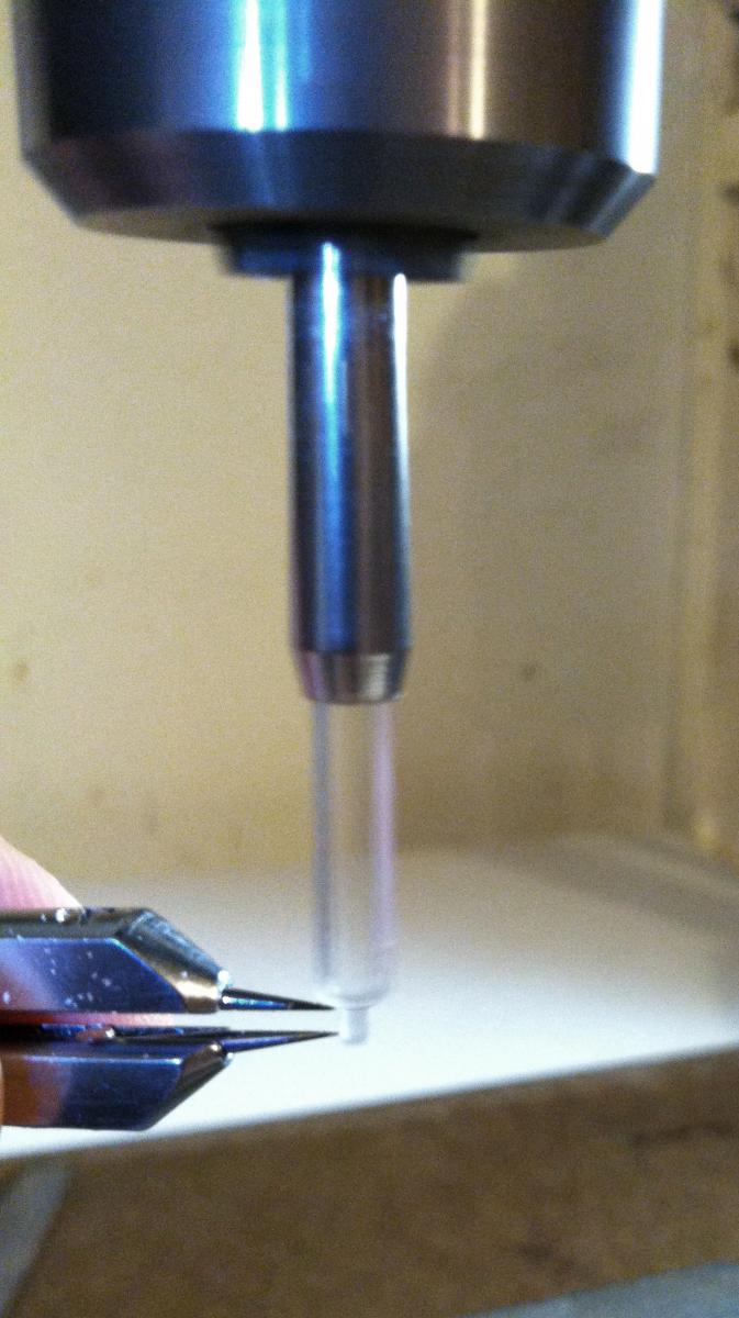
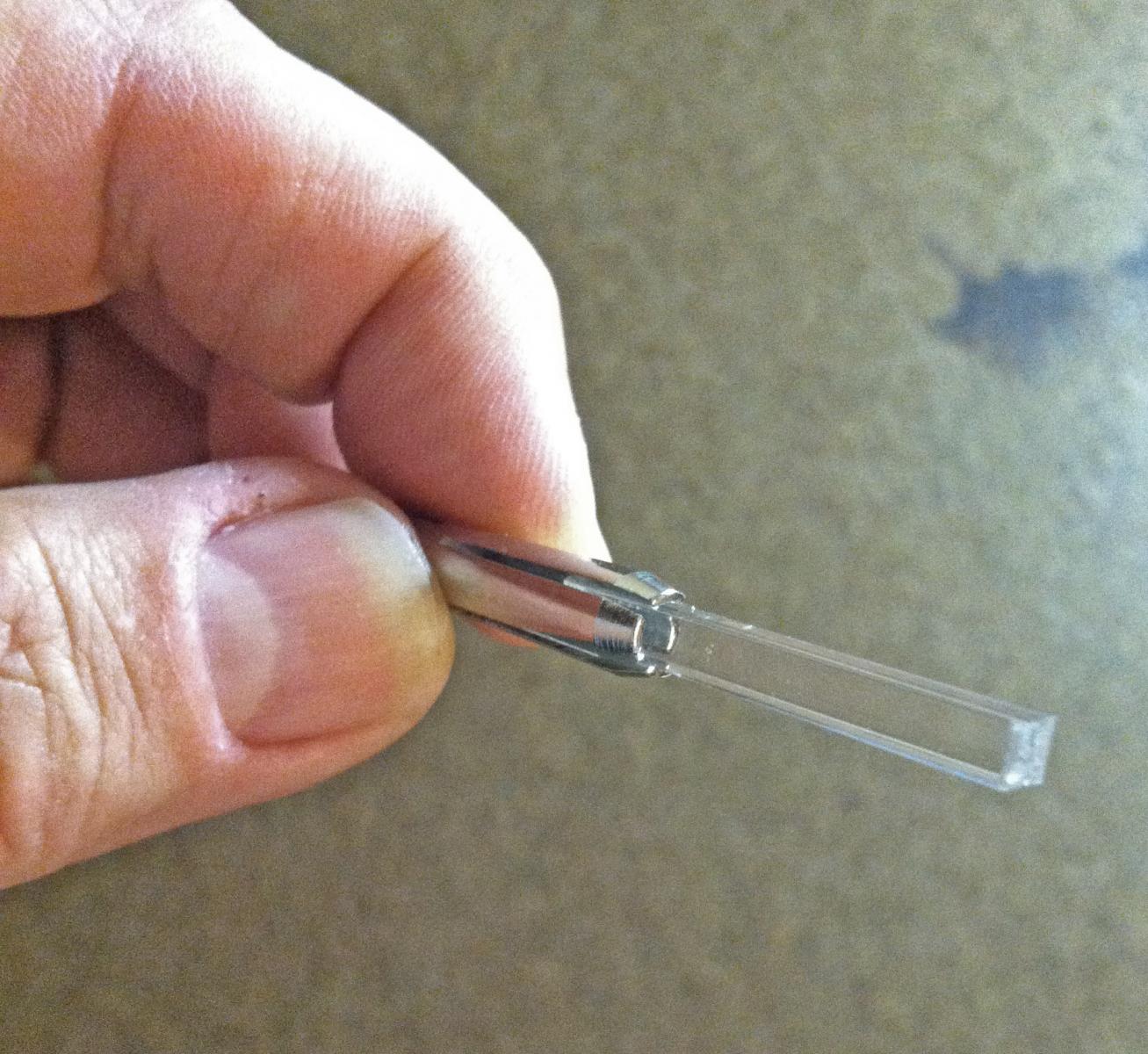
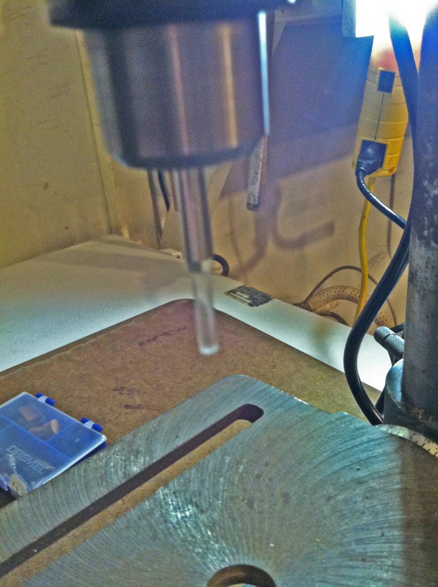
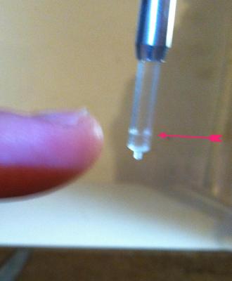
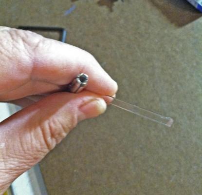
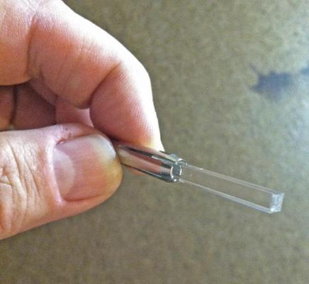
Just to note: I used fiber optic on my build for a couple of reasons. There are other options: i.e. incandescent grain of rice bulbs and ship mounted LED's. The incandescent bulbs are bright and have capabilities of easy brightness variability but they get HOT - dang hot. So much so that you can not touch them after running for a minute. So they either have to be well insulated from the plastic or incorporated into a wooden build which won't be as prone to heating (melting!). The ship mounted LED's are now much easier to incorporate but they also can fail over time or worse yet not light after the completed build for a variety of reasons - all of which you can't fix when the build is complete. Although fiber optic is a little bulky to work with it does not overheat, can only fail if you break the optic (not likely with careful handling) and allows you to put the light source and the electronics OUTSIDE of the build where they can be modified or repaired at any future date. So that is my reasoning and having said that I'll move on to how I made these lanterns and incorporated them into my Connie build. Before starting consider how the optics will exit your build. I chose to alter my Connie mounts to pedestal type and will add a third pedestal for the optic cables to transit. I used an 11/64" bit which exactly cut through the center of the keel without cutting keel sides. It allowed for ten 0.75mm optic cables to exit the hole without being too tight. The trick: centering the boat above the drill press to achieve the exact midline of the keel. With care this is not too difficult. First break off about 1 1/2" of the clear plastic stock (item 7) with the snips (item 17). Using the large end of the pin vise chuck (2) tap in the plastic so it is tight. (Note: I used the pin vise chuck because it has FOUR SIDES - the drill press chuck has three. It would have been easier to simply secure the plastic in the drill chuck - and I tried this - but it places the center of rotation away from the center of the plastic producing a non-symmetrical lopsided lamp. If you have or can find a drill chuck with 4 grips the centering in the drill would be a lot easier) Once you are happy with the placement put the pin vise chuck (2) into the drill press chuck and tighten the assembly. It does not have to be super tight but just tight enough to prevent slippage. Pin Vise chuck and Plastic stock Put together - trim until about 1" remains outside the chuck Use a low speed on the drill as high speeds will melt the plastic as you work with it (that is also why a Dremel does not work here - but you will need it later). Test the general centering by looking at the turning stock. If it seems to be wobbling slightly just turn off the drill press and re-center by tapping the piece lightly with a hammer. Repeat until the wobble is minimalized. If not minimized after a couple of taps you will probably have to start with a new piece. CENTERING THE PLASTIC IS A CRITICAL STEP TO GETTING A GOOD LANTERN. Up and spinning and CENTERED.

-
That is just too cool! It looks like a previous build may be at the bottom - is that a shipwreck? Dave
- 1,668 replies
-
- 1
-

-
- syren
- model shipways
- (and 1 more)
-
Good luck Verne. I can't wait to see how they turn out. I am especially looking forward to your research and it's incorporation into your build I think it adds a bit of excitment to the build (and maybe a little bit of intrigue!). Dave
-
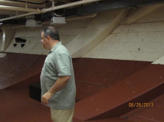
Actually Verne the knees, like Evan has said, are not well documented for 1812. But the diagonals to which I think you refer are on the Orlop deck and have nothing to do with the knees on the Berth and Gun decks. These same diagonals were removed from the ship in the early 1900's refit only to discover that the hog of the ship increased by 200%. They were reinstalled as laminated wood (no timbers of proper shape or size could be found anymore!) in the 1993 refit. The photo below shows Henry (popeye2sea) explaining these diagonals. You can see them in the background. Marquardt in his AOTS has a drawing of them as well. I will see if I can post it without getting into trouble...
- 135 replies
-
- 2
-
-
- Constitution
- Revell
- (and 1 more)
-
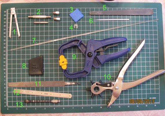
Several members over the last few months have inquired about some fiber optic lanterns I incorporated in my U.S.S. Constitution build and how to make them. Although some trial and error will occur for you (as with any new applied technique) I will highlight some of the details of the process I used to hopefully allow you to avoid some pitfalls. Let me start with tools you will need. Although this lantern process may seem tedious it is actually a lot of fun working with them and the rewards of lighting previously unseen areas of your build can't be beat. They do get easier as you do more of them. The tools I used are as follows: 1. Calipers (used to gauge the size of the plastic while it is being turned and shaped) These are EKG calipers that were given to me long ago. 2. Double end pin vise from Micromark tools: http://www.micromark.com/double-end-pin-vise,6729.html item #21104. I took mine apart and only used the large chuck (beneath the hand grip in the photo) to secure the plastic stock. 3. A slightly curved and cut paint stirring stick with blue painters tape applied. This is used to clamp the fiber optic into the ships bulwark and protects the model from the bite of the clamp. I added felt (not pictured) between the clamp as well for the same reason. 4. A plastic jig made from extra 1/8" plastic stock. More on this later... 5. Fine modelers sanding stick (or simply spray glue fine sand paper to another paint stick). 6. Micro brush - I believe this is a Microbrush product (http://www.microbrush.com/hobby/howtobuy/area.asp). 7. 1/8" Square clear plastic stock. This one is acrylic. I got mine from US Plastics item 44135 (http://www.usplastic.com/catalog/item.aspx?itemid=24195&catid=440&clickid=searchresults) BUT they only come in 6 foot sections! Shipping was more than the product...but there was plenty of it to experiment. Pictured is a 16" section. 8. Miniature drill bits. Any will do...mine are Micromark (http://www.micromark.com/20-piece-micro-size-drill-bit-set-with-index-61-80,6758.html) 9. 3" or 4" grip clamp to compress the fiber optic into the bulwark. 10. Leather punch for cutting out lantern reflectors. 11. Medium file with sharp fine teeth. Dull files will increase friction and thus heat, melting your stock. 12. An accurate ruler for setting the calipers. 13. A hand mini drill (Mine: Micromark http://www.micromark.com/micro-hand-drill,7045.html) NOT pictured: 14. Drill Press 15. Fiber OPtic cable (I bought plastic cable on Ebay - 0.75mm) 16. Dremel tool with a 1/32" engraving bit. 17. Beader's snips or tree snips. 18. Emory board 19. Flat Black Paint Next I'll describe how I used them.
-
I have had a few inquiries about the lanterns I made for this build. I will try to give a detailed account of how I did that. Only a few basic tools are needed and plastic stock. I'll get that description posted over the next few days for those interested. Dave
-
Just a heads up Verne: re-size your pics to 800 x 600 (or 600 x 800 if portrait oriented) to upload. I had some difficulty in the first log before realizing the size requirement. Dave
-
Nice to see you up and running Verne.
-
Hello Henry. I am just now experimenting with these hooks. So far not what I wanted but I am 'endeavoring to persevere.' 2mm beckets would be even trickier. A jig is an interesting thought. So far I have used round nose pliers with flat faced needle nose pliers. I have 26 gauge brass wire but the finished hooks are too big. Dave
-
Thank you Chuck. I had seen these blocks from your avatar but even up close they look superb! 50 per hour. Wow. Thanks also for including the wire size. I will double check mine. Some folks have used brass wire and blackened it. I may give that a try but I have already noticed a structural compromise in the metal integrity after blackening thinner items. From your description my tools may be my main issue. I need to get some better ones. I am heading out with my wife to shop tonight and I will keep at least one eye out for some replacements. Dave
-
There used to be a tutorial about making hooks for blocks and tackle but I do not see it on the MSW 2.0. It would be very helpful to have those tutorials or other folks voices of experience to help in this area of modeling - avoiding reinventing the wheel. Specifically I need to hook and block tackle from the Revell Constitution. I have experimented already but I am not happy with my results thus far. I will be working with 2mm single and double blocks and 0.20mm rigging line (both from Syren Ship Modeling Co.). Thank you in advance for sharing your experiences and techniques. Dave