Gahm
-
Posts
1,217 -
Joined
-
Last visited
Content Type
Profiles
Forums
Gallery
Events
Everything posted by Gahm
-
 Hey Richard, good to have you back! Your head rail really looks great! And talking about the lonely supply ship . . . well, it looks to me like I am plotting along in your wake Thomas
 -
Excellent job, Augie! You can soon think about your next project Thomas
-
US Brig Syren by Gahm - Model Shipways
Gahm replied to Gahm's topic in - Kit build logs for subjects built from 1801 - 1850
Hello Rusty, Thank you for stopping by. What are you up to in the moment? I followed your Syren build very closely, and I was totally in awe of your Confederacy. Both turned out absolutely beautifully! Thomas -
US Brig Syren by Gahm - Model Shipways
Gahm replied to Gahm's topic in - Kit build logs for subjects built from 1801 - 1850
Thank you, Chuck. The Syren really is a fun project! Thomas -
US Brig Syren by Gahm - Model Shipways
Gahm replied to Gahm's topic in - Kit build logs for subjects built from 1801 - 1850
Thank you, Augie! -
Beautiful work! Thomas
-
US Brig Syren by Gahm - Model Shipways
Gahm replied to Gahm's topic in - Kit build logs for subjects built from 1801 - 1850
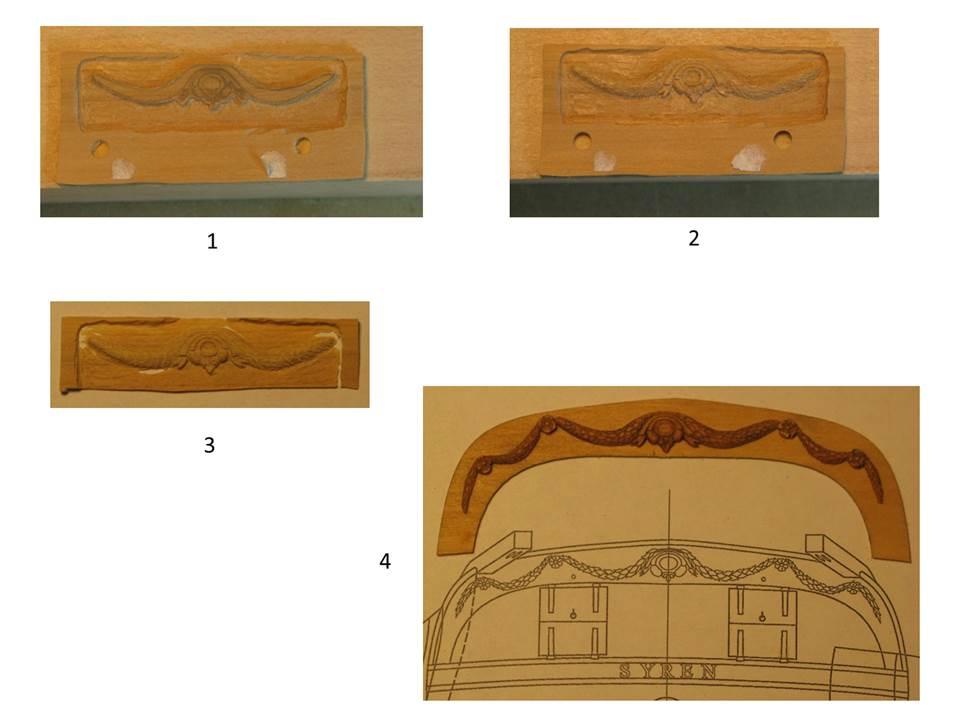
I finished the stern ornamentation. One of the biggest problems for me was (and still is) to find a good method to transcribe the drawings shown on the plan to the target piece of wood, which in this case was a piece of Swiss pear sanded down to about 5/64 inch. I chose the thickness of the wood slightly larger than what the ornament finally should be. As transcription method I ended up with using a copy of the drawings in the plan, blackened the backside of the paper with a pencil, placing the paper on the target wood and tracing the drawings with a pen. This leaves the traced part of the drawings as fine black lines on the wood. These lines I reinforced again with a pen (image1.1). However, I would highly appreciate ideas for better transcription methods! As a next step I glued the piece of wood with two little droplets of superglue on a larger block of wood for easier handling. Using a rotary tool as well as little chisels and an Exacto knife I first generated the coarse shape and then the fine details (image 1.2). Finally the wood piece with the carvings was detached from the wood block and sanded down until the wood matrix (background) disappeared (image 1.3) and only the carvings remained due to their larger thickness. This method allows generating carvings which ultimately are thin enough to match the scale of the model. Image 1.4 shows the finished result, images 2 and 3 show the Syren’s stern with the mounted ornamentation. Production of stern carvings. Mounted stern carvings. Stern view of Syren with mounted carvings.
-
Hi Augie, Great to see your building log coming up again! I always love to watch your progress! It gives me an indication what I still have ahead of me Thomas
-
US Brig Syren by Gahm - Model Shipways
Gahm replied to Gahm's topic in - Kit build logs for subjects built from 1801 - 1850
Augie, Mark, Chuck, I just finished uploading my Syren build log and saw your kind remarks. Thank you very much! And by the way, the new site is great! Everything works so much better and is so much more up to date than it was before! Great job! Thomas -
US Brig Syren by Gahm - Model Shipways
Gahm replied to Gahm's topic in - Kit build logs for subjects built from 1801 - 1850
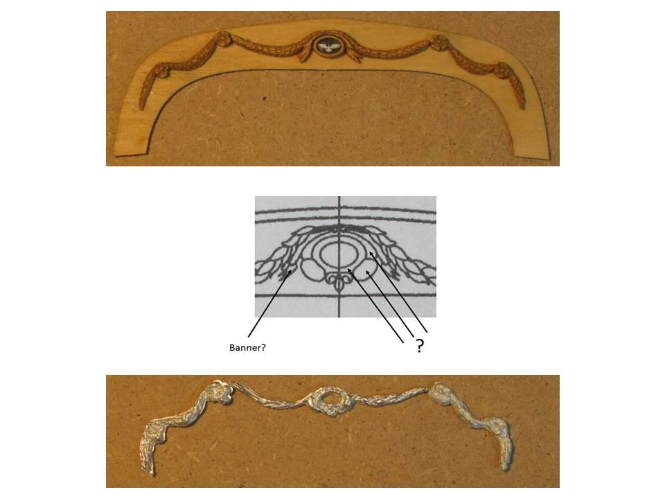
Test fitting of quarter gallery. I started to give the stern carvings a try. During this process I realized that I did not really understand the components of the central part of these ornaments. As a first attempt I tried to realize a medallion with two banners and a little eagle in the middle . . . however I really would love to understand what should be there so that my next try might get a little closer (-:

-
US Brig Syren by Gahm - Model Shipways
Gahm replied to Gahm's topic in - Kit build logs for subjects built from 1801 - 1850
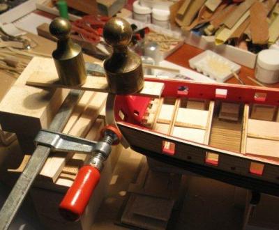
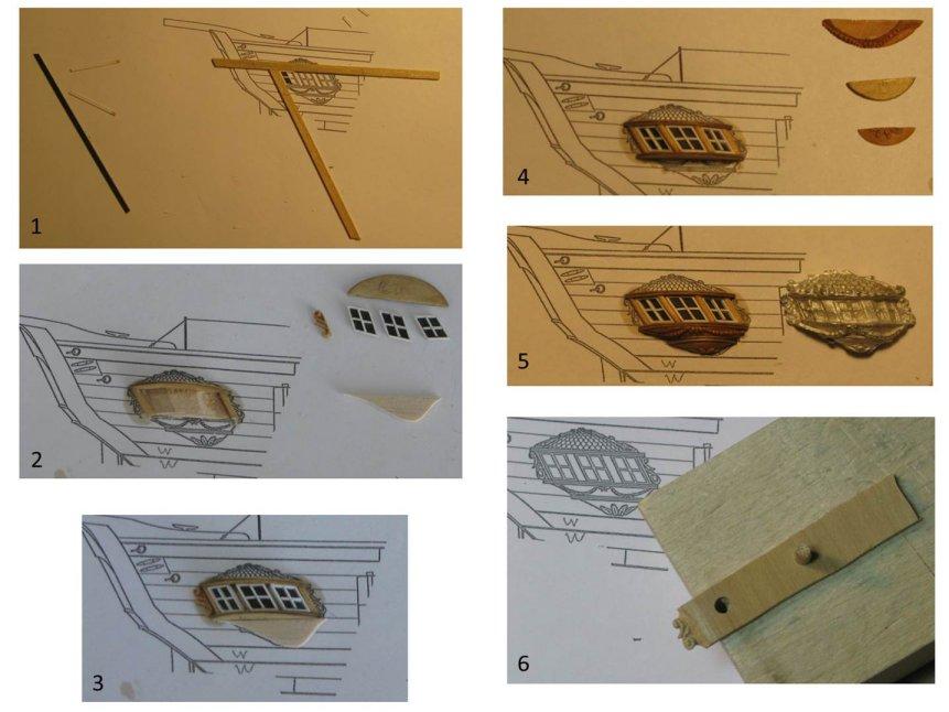
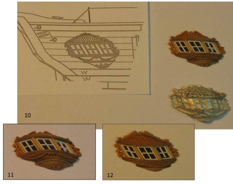
Building of the rudder. Finished pintles and gudgeons. Several views of Syren with mounted rudder: Building of the starboard quarter gallery. The windows are constructed out of birch veneer and bass wood (1). (2) shows three finished windows and the main gallery body, in which the windows are test-fitted (3) and finally mounted with separating columns (4). At the right side of image 4 the carvings of the lower gallery body are lined up. From top to bottom: chains, moldings, leafs. 5 shows the assembled gallery body. 6 depicts the carving of the side ornaments. Images 7, 8 and 9 show the construction of the roof with the backplane carvings and the shingle body. The shingle body on the right side in image 9 (3rd carving attempt) was used for the final assembly. Different views of finished quarter gallery along with Chuck's plan and the metal casting from the Syren kit.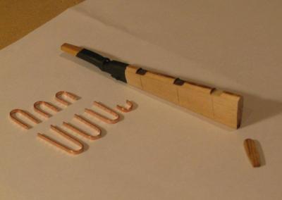


-
US Brig Syren by Gahm - Model Shipways
Gahm replied to Gahm's topic in - Kit build logs for subjects built from 1801 - 1850
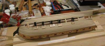
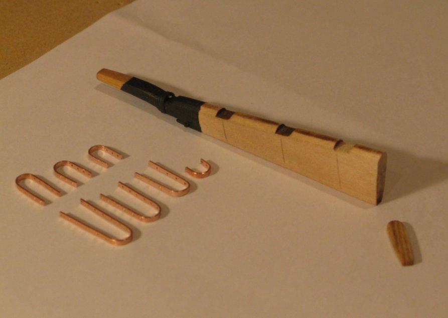
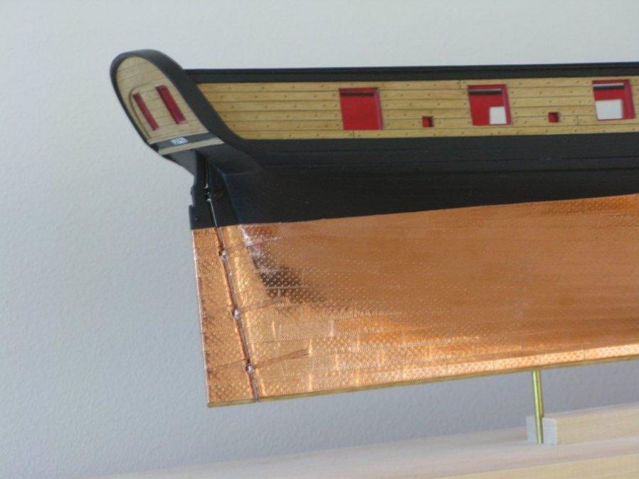
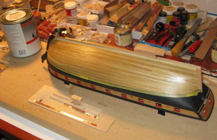
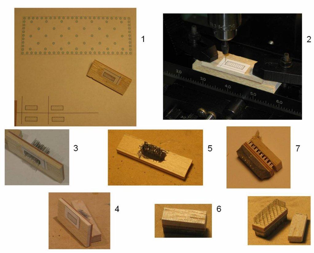
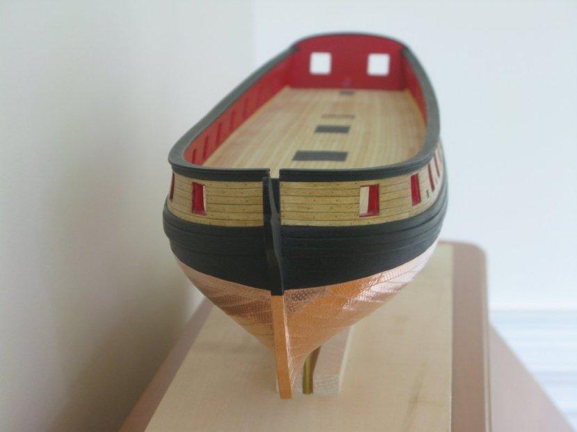
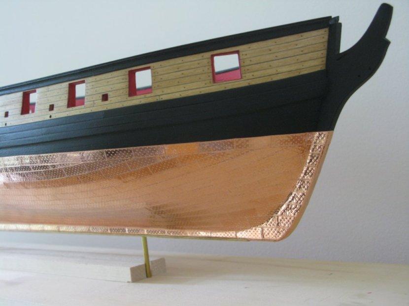
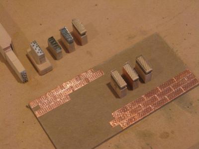
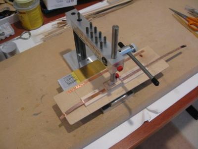
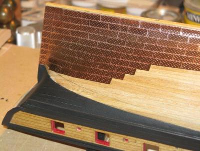
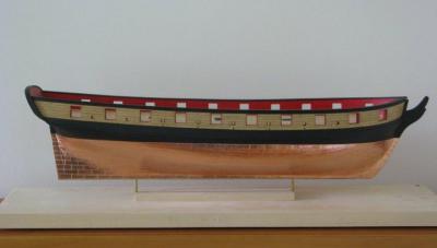
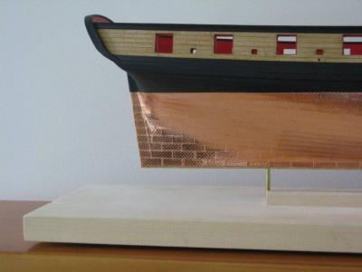
The copper plating of the hull is finished. After experimenting with different nail patterns I finally settled for one. The following images show the hull preparation, the production of the nail head using a variation of Alan’s method with the diabetes needles, and the resulting copper plating. I first prepared the hull by filling every hole with wood filler, treating the hull with MinWax Sanding Sealer and sanding it down to a very smooth finish. To produce the nail head I designed the desired pattern with MS PowerPoint, shrank it to the right scale and printed it out (image 2.1). I glued the image of the nail pattern on a piece of 3mm thick balsa wood which in turn was glued to a thin piece of plywood. I made sure that no glue was between the balsa and the plywood under the area where the printed image of the nail pattern resided. Using a #80 drill (~0.3 mm diameter; Micro-Mark) and a micro pin chuck (Micro-Mark) mounted in my drill press I drilled the holes for the nail pattern (image 2.2). The soft balsa wood allows the thin drill to proceed without bending. Once the drill hits the hard plywood the drill channel in the balsa wood acts as a guide for the thin drill ensuring that it enters the plywood without being deflected or bent. Next I removed the metal needles (~0.3mm diameter) from the plastic heads of the diabetes needles bought at Wallmart with a pair of pliers and inserted the needles into the drilled holes (image 2.3). Pushing the balsa wood surface against a flat piece of metal ensures that all needles end in the same plane (image 2.4). The needle ends sticking out of the plywood side were glued together with JB Weld (image 2.5). Now the nail head can be cut out according to the drawing glued on top of the balsa wood. The balsa wood surface is then sanded down until all needles show a complete diameter perfectly aligned in the balsa wood plane (image 2.6). As a next step the balsa wood can be separated from the plywood (for this reason it is important to have no glue between balsa and ply wood underneath the nail pattern drawing, see image 2.7) and the nail head is finished. Experimenting with different nail patterns. The 3 nail heads in the front were used for my model – one for starboard, one for backboard, and a symmetric one for the dress belt. The “Sensipress” (Micro-Mark) came in handy for the copper plate mass production. Resulting copper plate pattern. Here are some additional views of the copper plated hull:


-
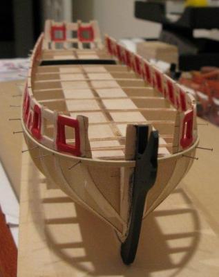
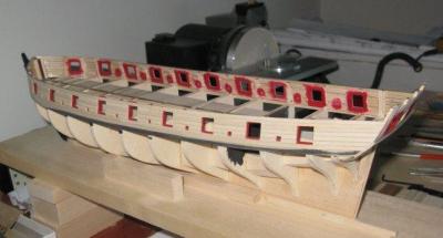
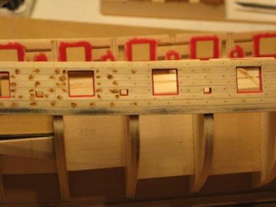
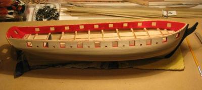
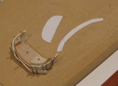
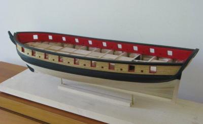
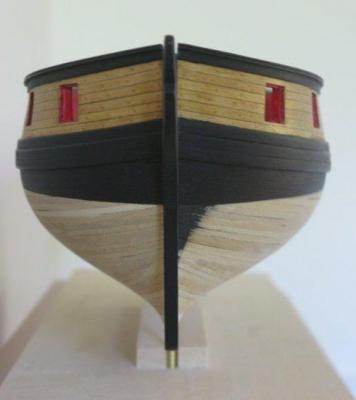
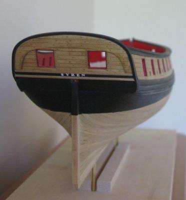
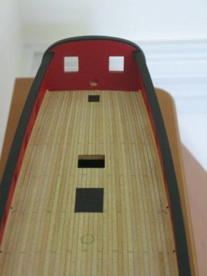
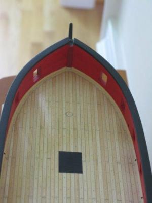
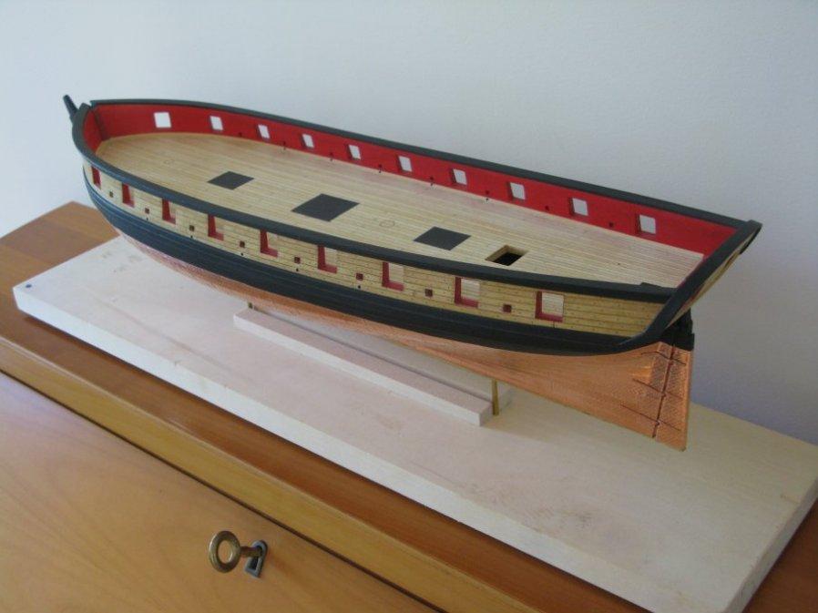
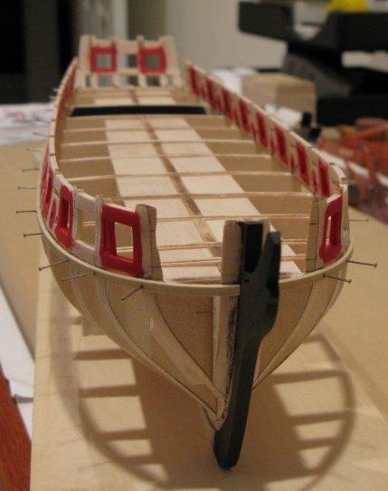
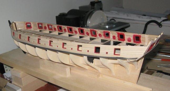
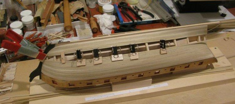
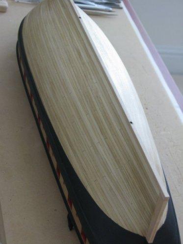
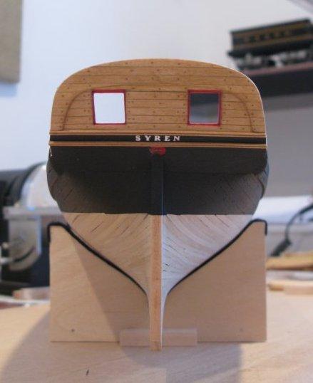
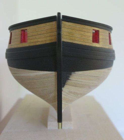
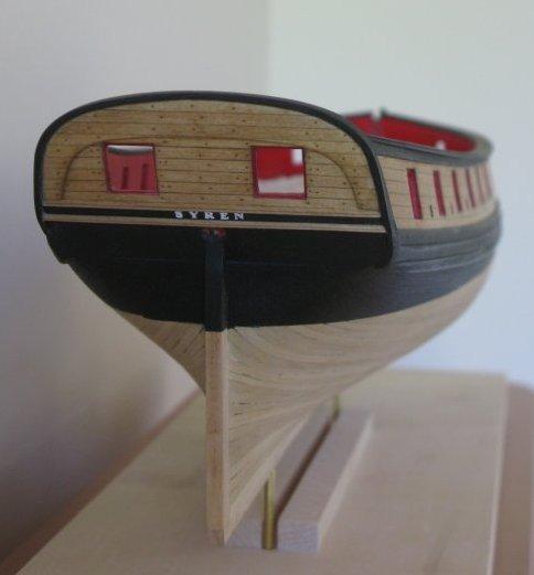
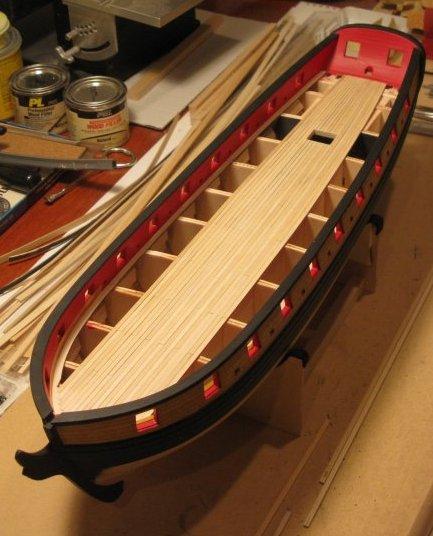
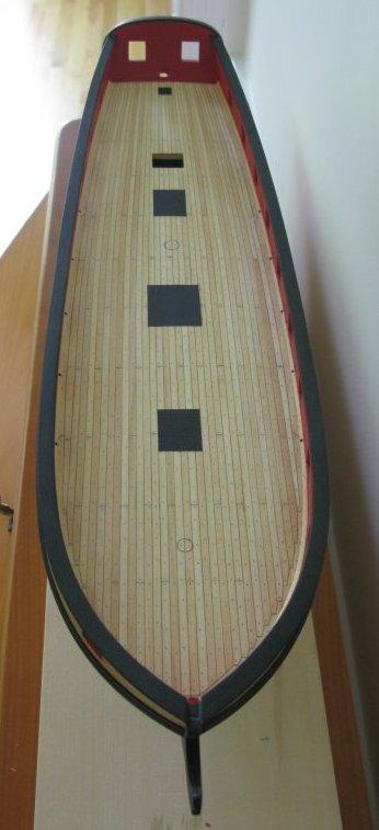
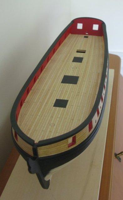
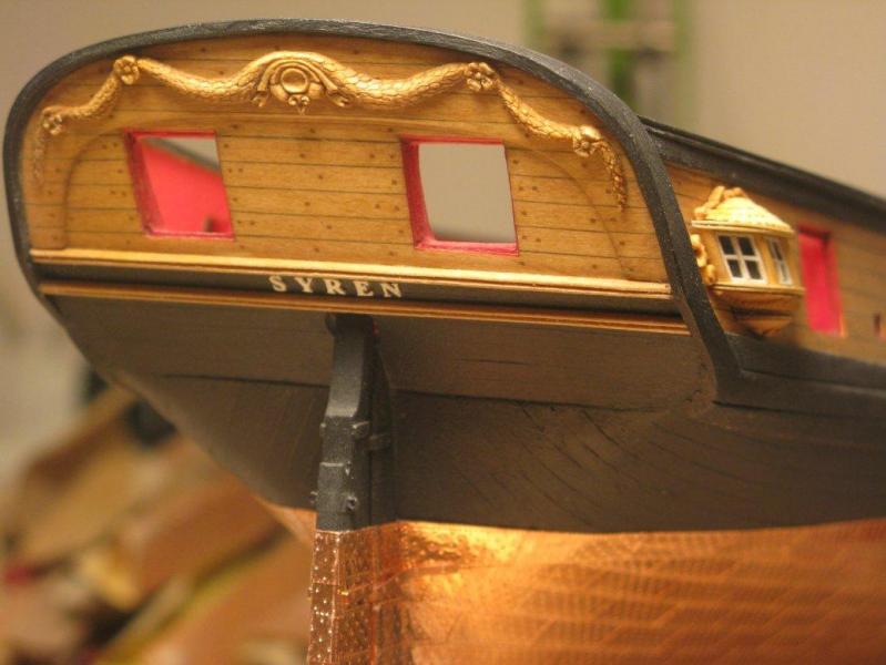
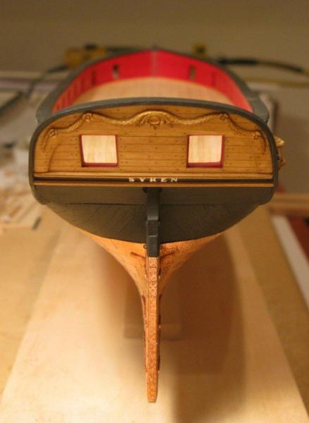
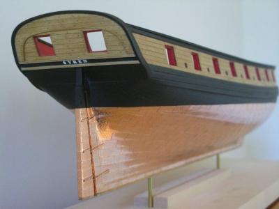
Hi, my name is Thomas Gahm. My build log disappeared as so many others during the recent crash, and I just try to reconstruct as much as I can. Bulkheads and filler blocks are being glued in place. Gun ports are framed and the fairing of bulkheads is finished. Planking of the upper part of the hull with bass wood strips. The strips were selected for homogeneous color and texture. Treenailing using the wood filler based method described by Chuck in the instruction book. During my last ship model build (Anfora kit Ictineo II) the combination of the applied wood stain and the slight fuzziness of the treenail hole edges led to a larger treenail appearance than initially intended. To avoid this effect I drilled holes which were slightly smaller than the intended treenail size of 0.5mm and I opened them up with a needle of a slightly larger diameter (0.53mm). This led to well defined, round holes with sharp edges, which once filled with wood filler gave me the intended treenailing effect. Planking of the lower hull with bass wood strips. As this part of the hull will be covered later by copper sheaths I did not particularly select the wood strips for texture or color. Finished hull planking. Lower part of hull planking. Two brass pipes were buried in the keel to allow for the possibility to mount the model later via two brass carriers inserted in these pipes. If these mounts should not be needed the holes can be covered up via the false keel. Stern view of the Syren. Mounting the Syren name turned out to be a bit tricky due to the small size of the photo etched letters. The following method worked for me: I painted the letters (white) while they were still attached to the photo etch grid. After separating them from the brass grid I arranged them to form the name “SYREN” on a sticky tape mounted on a flat piece of wood with the sticky side up. Once I was satisfied with the arrangement of the letters I covered them with a second piece of transparent tape with the sticky side towards the letters. After turning the whole arrangement upside down so that the first tape was on top and the second tape underneath the letters I removed the first tape while carefully making sure that the letters did not come loose from the second tape. Now all that remained to do was to apply some superglue to the uncovered letter backs and transfer the name as a whole in its final arrangement to its destination on the stern. The use of a transparent tape allowed for precise positioning. Once the letters were glued to the hull the tape could be removed. Building of the stern transom. To form the stern transom I modeled it first with a piece of paper which I then used to cut out the wooden (bass wood) counterpart. This was then soaked in hot water and bent to its final shape in a jig. The formed transom is glued in place. Finished transom. Front view of the Syren. The planks are stained with a mixture of 1 part Minwax Golden Oak and 2 parts Minwax Natural wood stain. Stern view of the Syren. Planking of the deck using selected basswood strips. The planks were tapered towards the stern. Finished deck planking with waterways. I painted the locations of the future gratings black to prevent the possibility of the deck planking to be seen through the openings of the gratings. The deck was stained with Minwax Natural wood stain. Stern view of the deck with treenailing. Plank nibbing. Deck view.