
JerryTodd
-
Posts
879 -
Joined
-
Last visited


-
 JerryTodd reacted to a post in a topic:
HMCSS Victoria 1855 by BANYAN - 1:72
JerryTodd reacted to a post in a topic:
HMCSS Victoria 1855 by BANYAN - 1:72
-
JerryTodd reacted to a post in a topic:
My Rope Making Machine ( Rope Walk )
-
JerryTodd reacted to a post in a topic:
La Créole 1827 by archjofo - Scale 1/48 - French corvette
-
JerryTodd reacted to a post in a topic:
Gary Thomas by J Snyder - 1:16 - William Atkin 25 foot Sloop
-
JerryTodd reacted to a post in a topic:
Trireme Olympias by Richard Braithwaite
-
JerryTodd reacted to a post in a topic:
Trireme Olympias by Richard Braithwaite
-
JerryTodd reacted to a post in a topic:
Trireme Olympias by Richard Braithwaite
-
JerryTodd reacted to a post in a topic:
Herzogin Cecilie 1902 by Jim Lad - Four Masted Barque
-
JerryTodd reacted to a post in a topic:
Attention: New Members and Your Screen Name
-
Zvr reacted to a post in a topic:
HMS Macedonian 1812 by JerryTodd - 1:36 scale - RADIO
-
Keith Black reacted to a post in a topic:
In which offense is taken (or, "hey! I resemble that remark")
-
tlevine reacted to a post in a topic:
Keel first before planking?
-
vvvjames reacted to a post in a topic:
In which offense is taken (or, "hey! I resemble that remark")
-

In which offense is taken (or, "hey! I resemble that remark")
JerryTodd replied to Cena's topic in New member Introductions
I doubt he was envisioning that, at all. A plastic kit is gluing parts together. He's referring to wooden kits that require shaping semi-made parts and strips in addition to gluing parts together. Granted, many want more from their plastic kit, and there's a few Revell Constitution and Heller Victory logs here on MSW where you can see the lengths some folks go to to super-detail their kit, rather than build out of the box. Still, I doubt a Revel Constitution has a record of knocking people out of the hobby to match a Caldercraft Victory. -
Pierre Greborio reacted to a post in a topic:
Keel first before planking?
-
Paul White reacted to a post in a topic:
Keel first before planking?
-
You can't put skin on a critter that has no bones! Most kits are "plank-on-bulkhead" construction. They consist of an inner form or strong-back, sometimes called an inner keel, or false-keel, but is probably best called the keel-son. The forms, probably called frames in the kit's instructions, notch into the keel-son to make the skeleton of the model. Kits generally use two layers of planking to use thin veneers that are easier for the average modeler to work with, and a cheap way for the manufacturer to provide pretty wood that's usually a pain to work otherwise. The first layer is often basswood/lime which modelers often apply willy-nilly because "no one will see it" and the outer layer of some junk wood that happens to finish pretty and is also applied willy-nilly because the kit's instructions don't tell how a boat's really planked because they don't know themselves (judging by the photos of the one they built) Anyway, A house has to have a framework before it gets sheathing, siding, roofing, etc, so build the frame first! Look at the build logs here on MSW and you'll see the process, as well as some extra work people often put in to make sure the framework is sound before starting the planking.
-
JerryTodd reacted to a post in a topic:
USS Constitution by mtbediz - 1:76
-
PaddyO reacted to a post in a topic:
Copper plate overlapping (< > 1794) - lower overlaps upper or vice versa?
-
ccoyle reacted to a post in a topic:
Copper plate overlapping (< > 1794) - lower overlaps upper or vice versa?
-
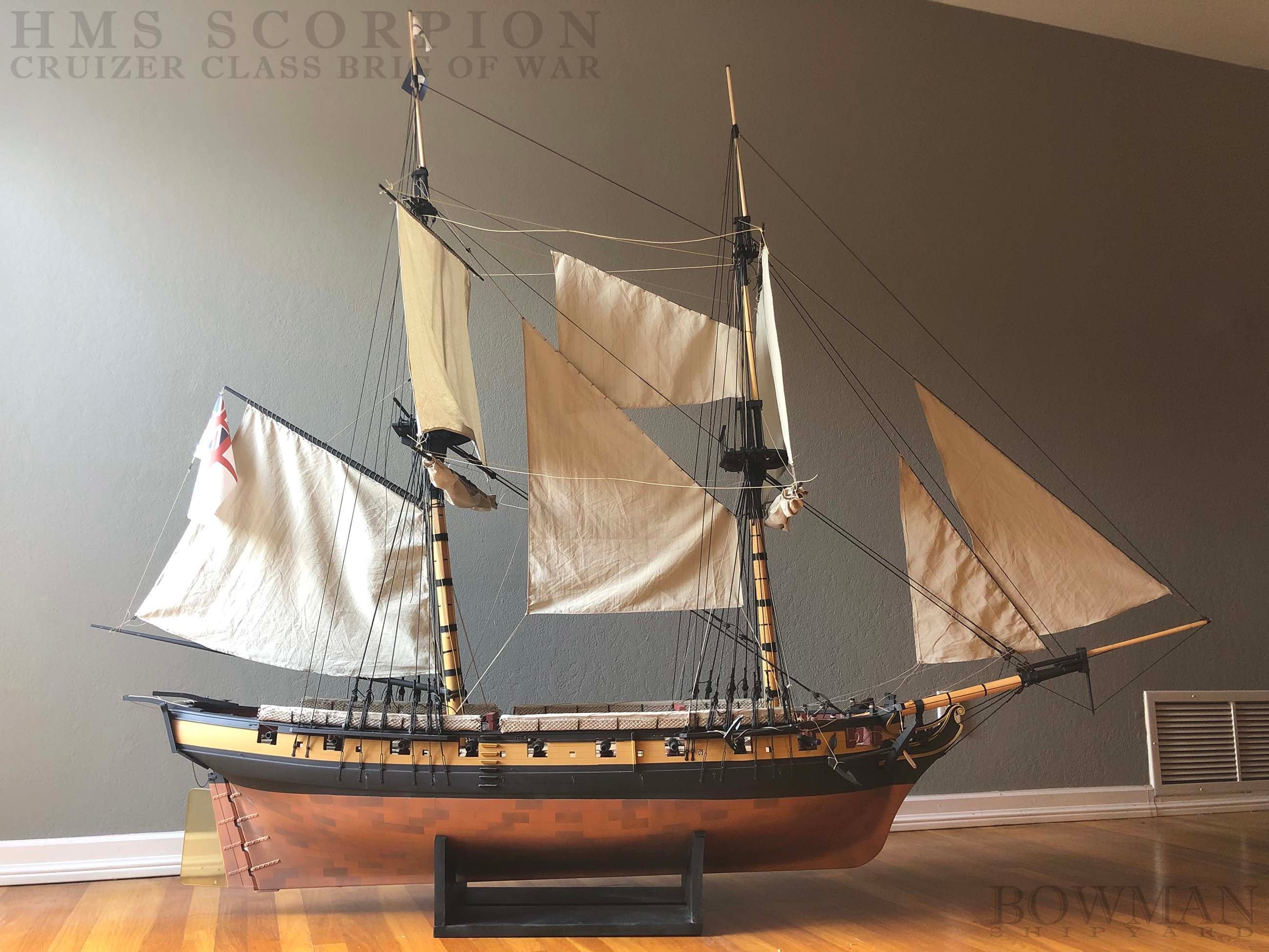
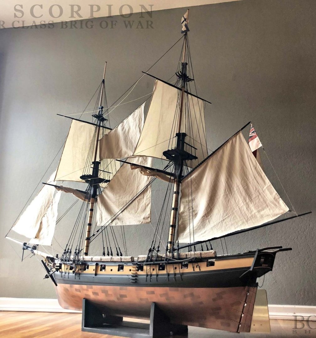
There's no rule that says you can't just paint the coppering. Here Tim Bowmen used several masks and tints of copper to imply the copper bottom on his 1:24 Cruiser class brig Scorpion, making sure the layers went on in the right order to give an edge to the plates. I've seen this technique used on steel warships to imply plating without exaggerated thickness on a 1:350 scale model. click for larger images...

-
PaddyO reacted to a post in a topic:
Copper plate overlapping (< > 1794) - lower overlaps upper or vice versa?
-
Harvey Golden reacted to a post in a topic:
Sail feedback request, Mondfeld method
-
Sail feedback request, Mondfeld method
JerryTodd replied to travis's topic in Masting, rigging and sails
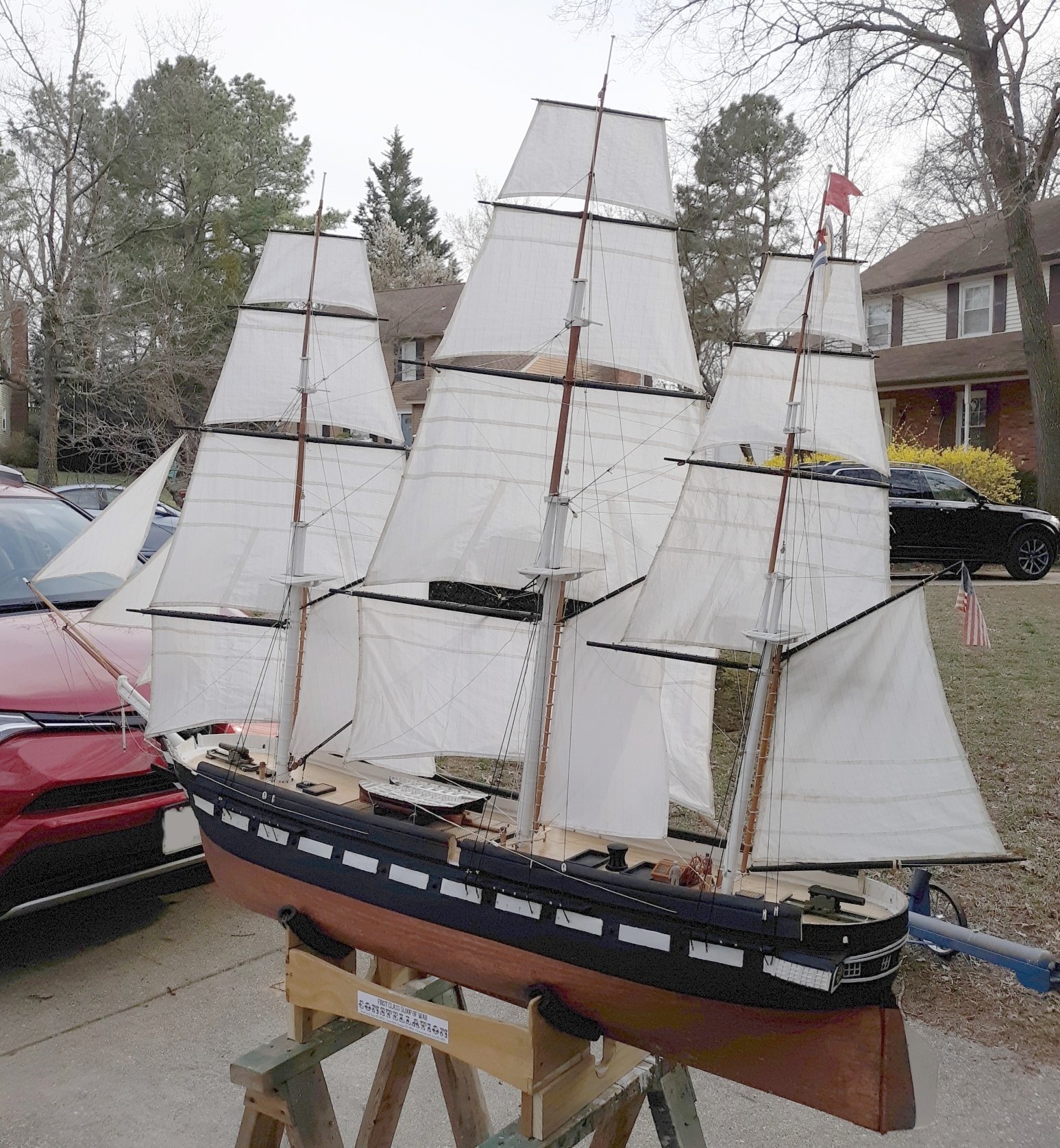
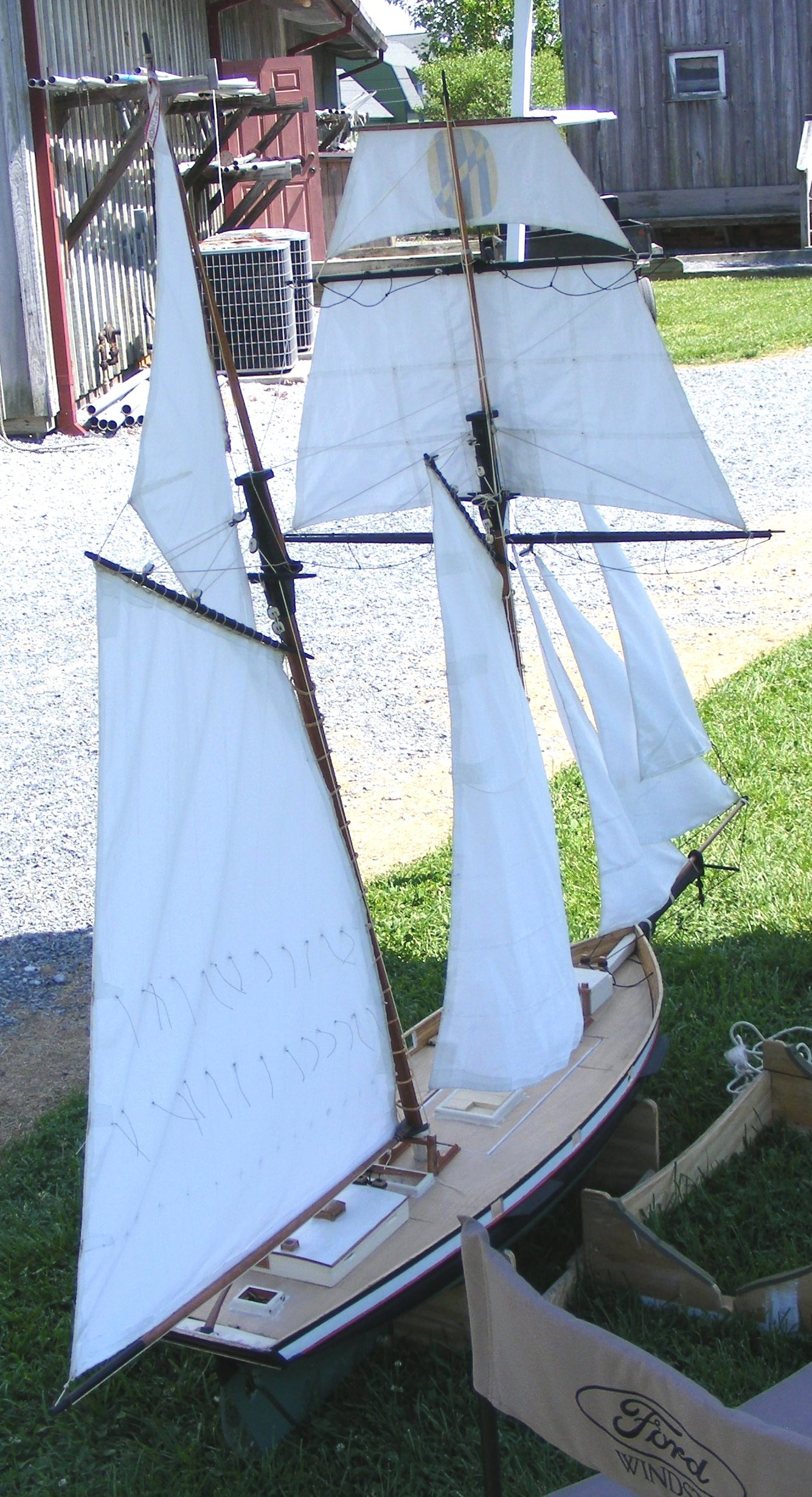
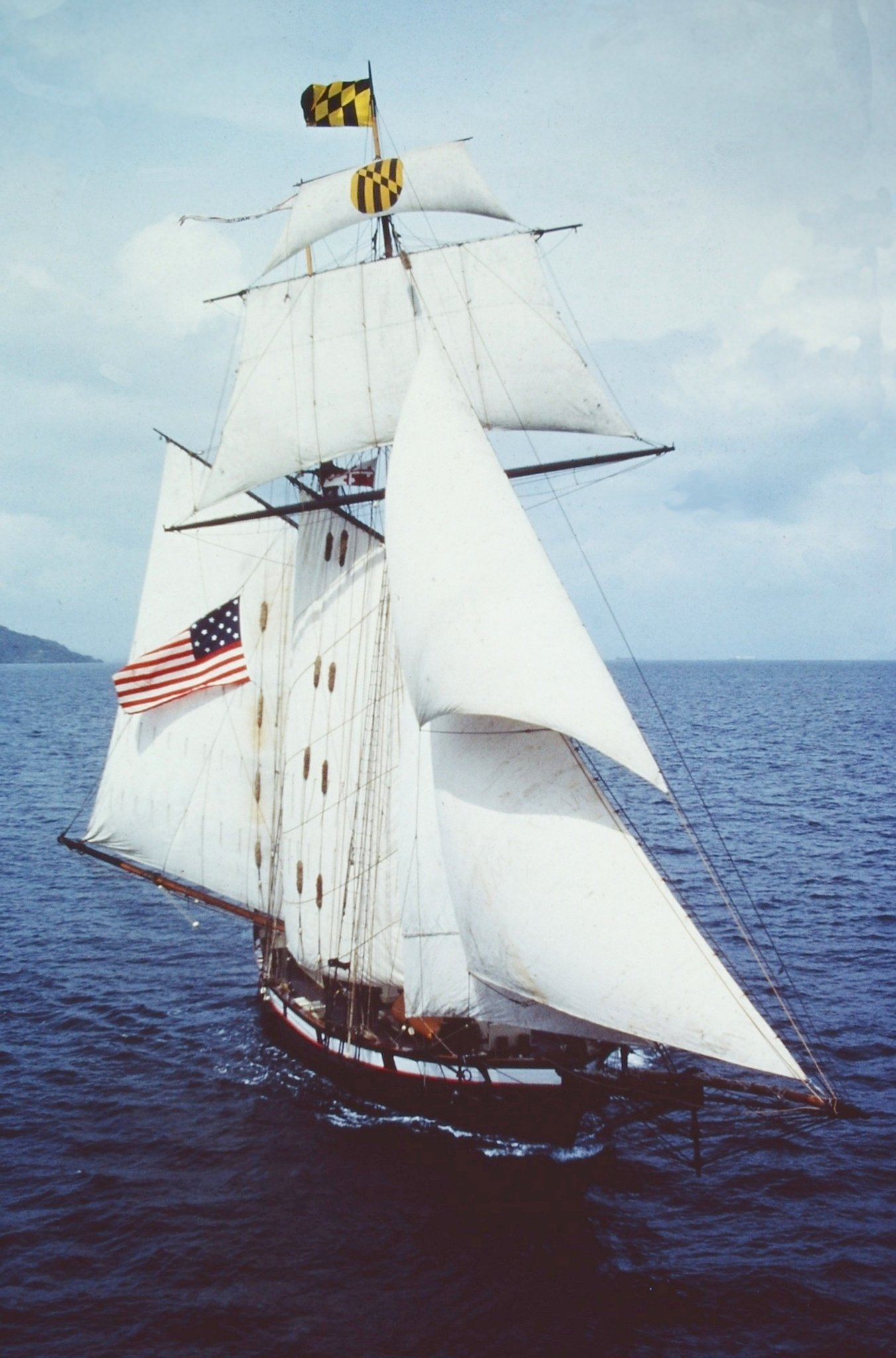
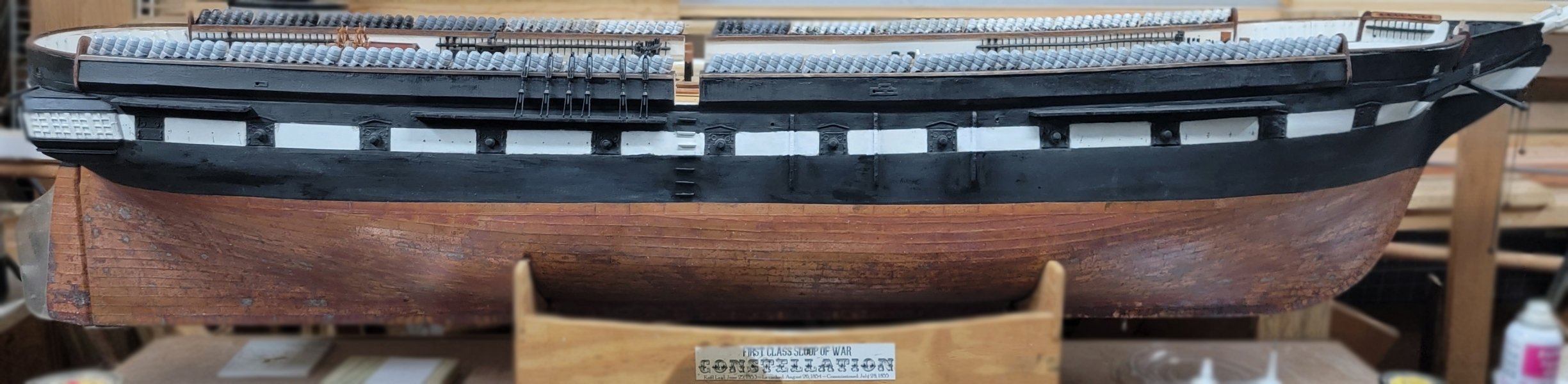
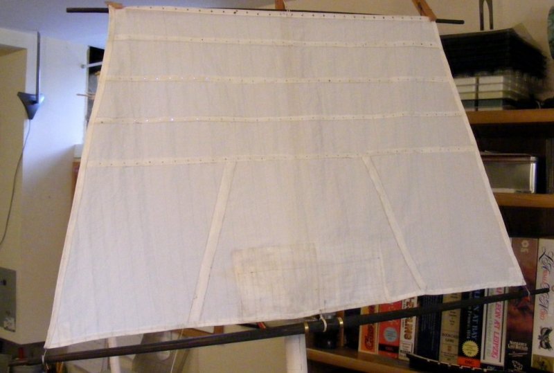
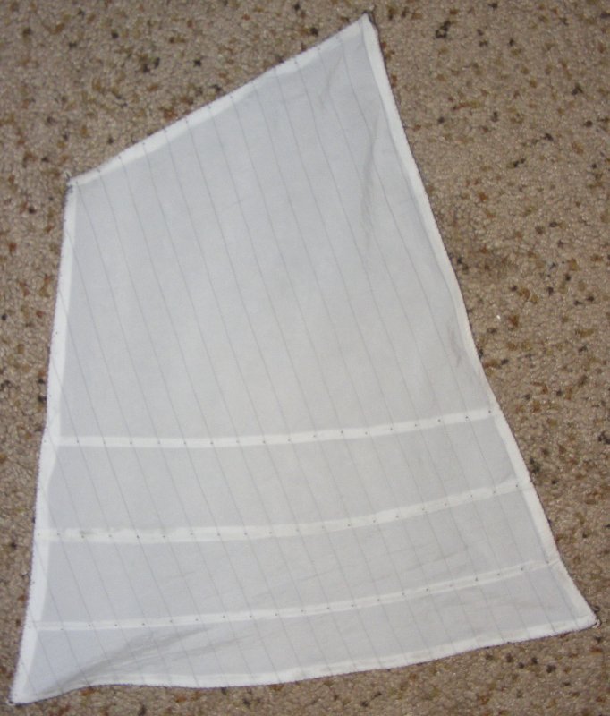
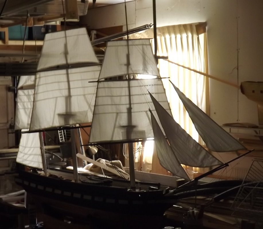
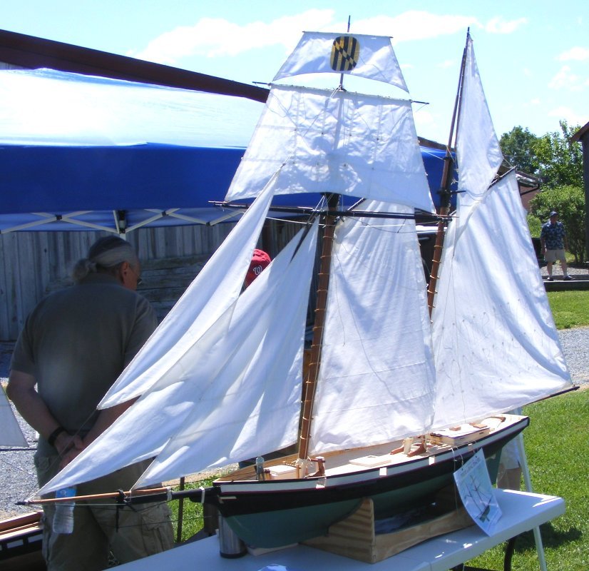
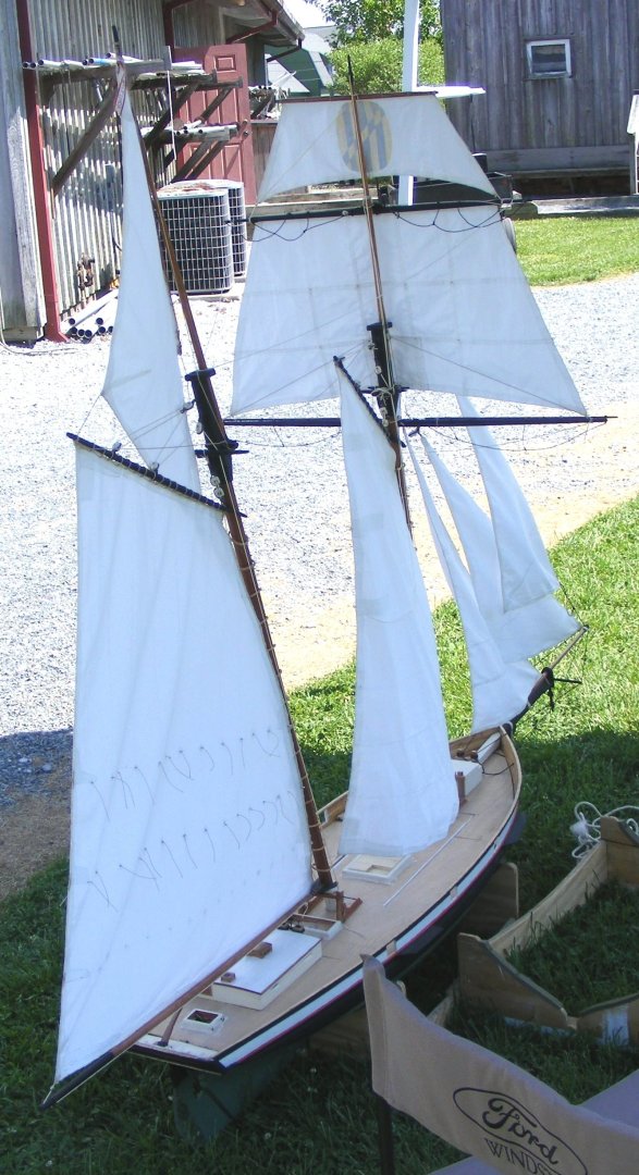
There's way too much focus on seams. The only reason you see seam on real sails is because the material is 4 layers thick (2 layers on modern sails), and that's when the light's behind them. When the light's in front, you see the shadow of the edge of the seam. Most kits run in the 1:64 to 1:48 scale range, for square-riggers, and the thread in those stitch-line "seams" scale from the size of a man's wrist, up to nearly the size of a tow-cable in diameter! - a bit much to represent a shadow. Most kits, especially the ones anyone can afford, are filled with parts-bin parts that don't match the model's scale, and wind up being much to oversized and clunky looking, and in rare cases, under-sized and diminutive. Any sail-cloth included is usually some burlap looking muslin scraps from an upholstery shop, that sometimes they run some anchor-chain through to save you the time making them even worst. I personally think the best approach is to imply the shadow of the seams by drawing them on with fine (.03) permanent marker. I draw all the seams on one side of the sail, and again on the other side just a little off to imply seam width. My sails may not be fair representations as they are made for working models at a larger scale than most static models (1:36 & 1:20), but they do show the effect of drawn seams, which also don't suffer from puckering the way stitch-line seams do. (click the pics till you get them full-size) The actual boat for comparison...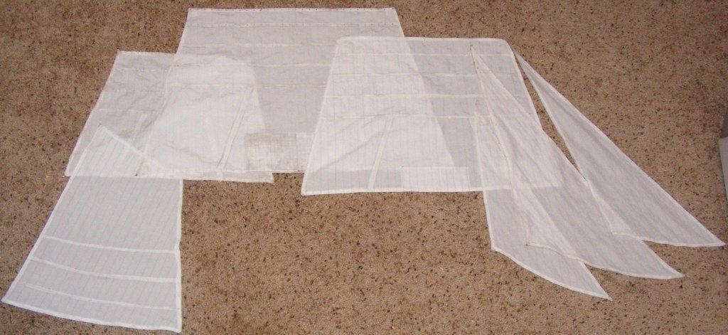


-
I like big boats and I can not lie... Though I do prefer mine to swim
-
The bowlines purpose is to pull the windward edge (luff) of the sail forward when on-the-wind (beam-reach to close-hauled), so they would need to lead forward of where that edge of the sail would be when braced hard over, same with the tacks.
-
Possibilities of a visual reference for sail configurations
JerryTodd replied to N Mart's topic in Masting, rigging and sails
John Harland's Seamanship-in-the-Age-of-Sail https://www.amazon.com/dp/1472982371/ref=olp-opf-redir?aod=1&ie=UTF8&condition=ALL -
A long time ago, the Naval Academy had the Macedonian figurehead scanned to create a 3D model. The people that did the scan found my, and my Macedonian model and offer to 3D print one for me for $250. I couldn't justify $250 for a 2 inch tall bit of plastic, so I declined. Years later, having my own 3D printer, I contacted these people hoping to may get a file I could accurately scale and print. They replied after several attempt to contact them, that they could not distribute the file because it was US Navy property. Then I found it posted on a public site, not downloadable, and with no contact information. Still there: https://sketchfab.com/3d-models/usna-macedonian-monument-uwSAs3DI5gtIRlQtrtFYfUcJbp6 Constellation's been without her head ornamentation for some time now. Figuring they're looking to replace it with reproductions and would have it scanned much how the USNA did with Macedonian's figurehead, I contacted Historic Ships Baltimore to inquire if that's the case, if so, was there a chance of getting copies of the files, and explained why I was asking. In short, the answer was "I don't know, but I presume NO." Out of curiosity, I checked my bookmarks to see if the Macedonian figurehead was still on SketchFab, and it was. Interestingly, on the right column was a "Billet_head" posted by the same Direct Dimensions only a month ago! Well if it isn't a scan of Constellation's billet-head, but wait, there's more... Going to their Sketchfab page, to see all their 3D model uploads, I found scans of Constellation's trail-boards! None of this is downloadable, and there's still no contact information, so... Billet-head: https://sketchfab.com/3d-models/billet--head-3mill-mm-d1422e4df6454a3dbea26ea5058d7109 Trail-boards: https://sketchfab.com/3d-models/us-constellation-filligree-43b0610e75c5460ea3661a33b92a79ec There's functionality in the Blender software to basically make a contour model from a shaded image, just like these. I hope using the best screen-shots I could manage will allow me to use that feature to finally produce Constellation's head ornamentation.


- 553 replies
-
- 2
-
-
- sloop of war
- constellation
- (and 3 more)
-
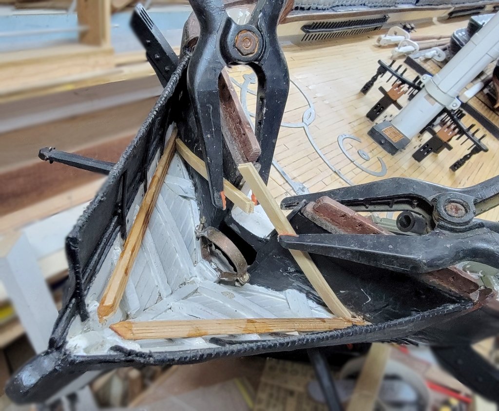
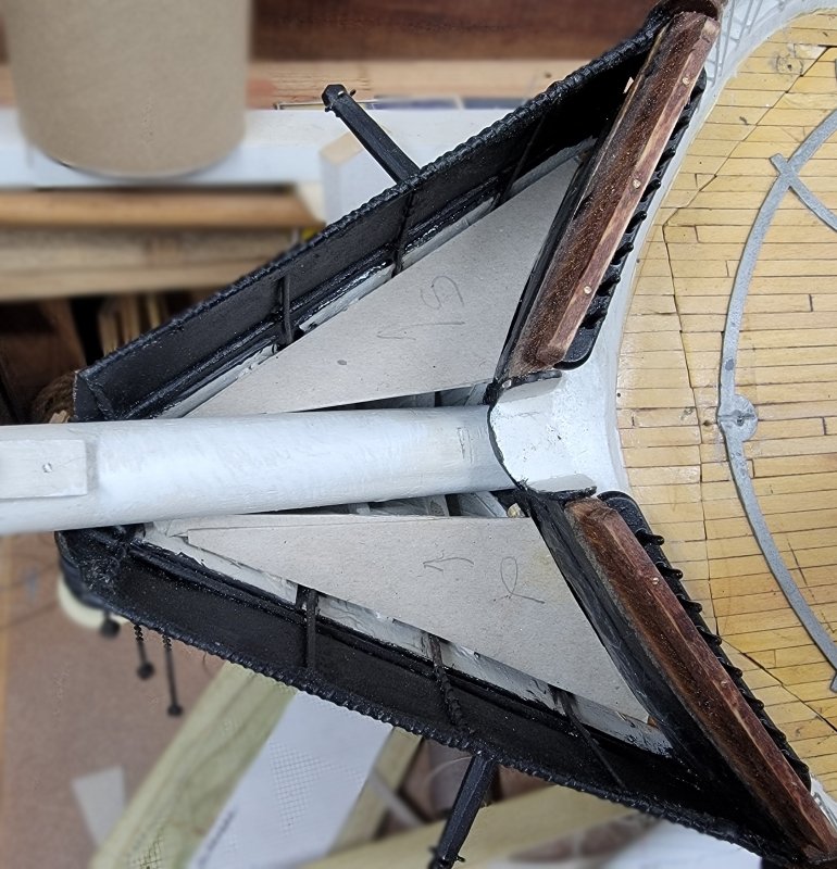
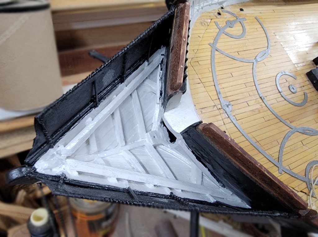
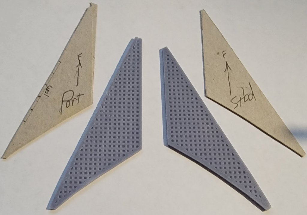
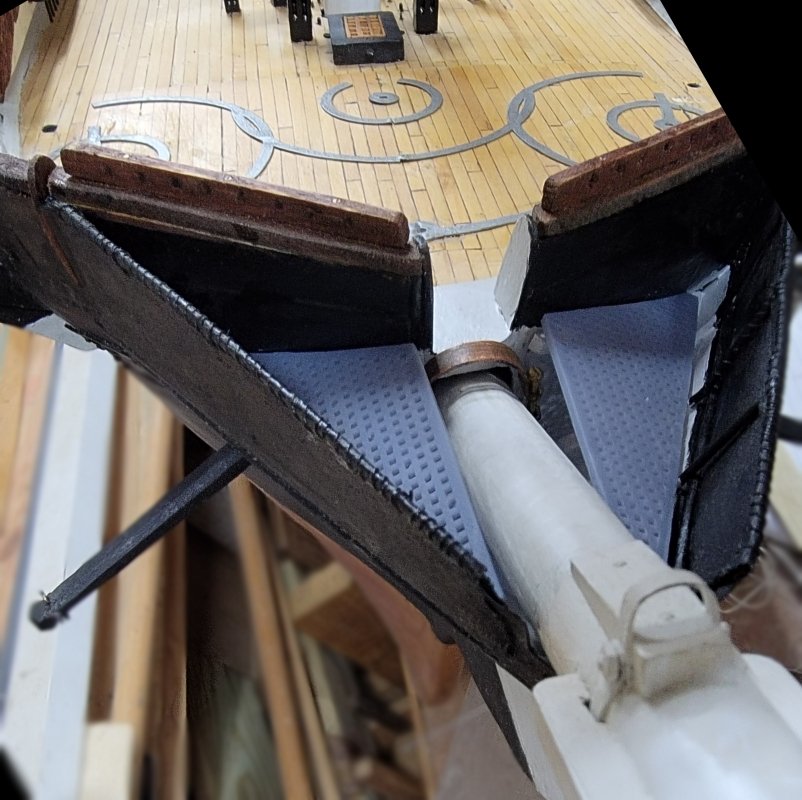
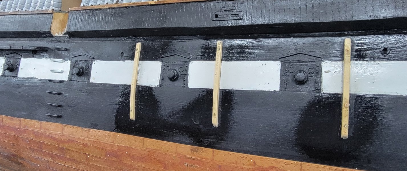
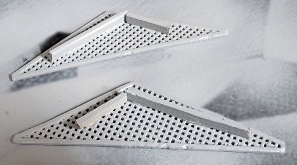
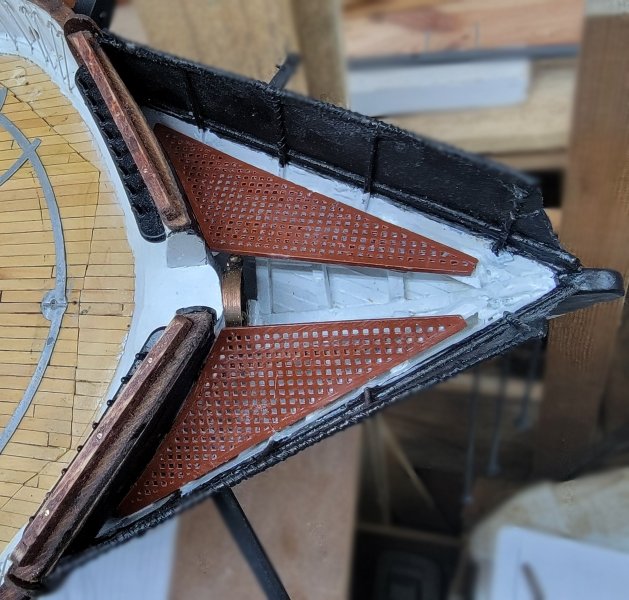
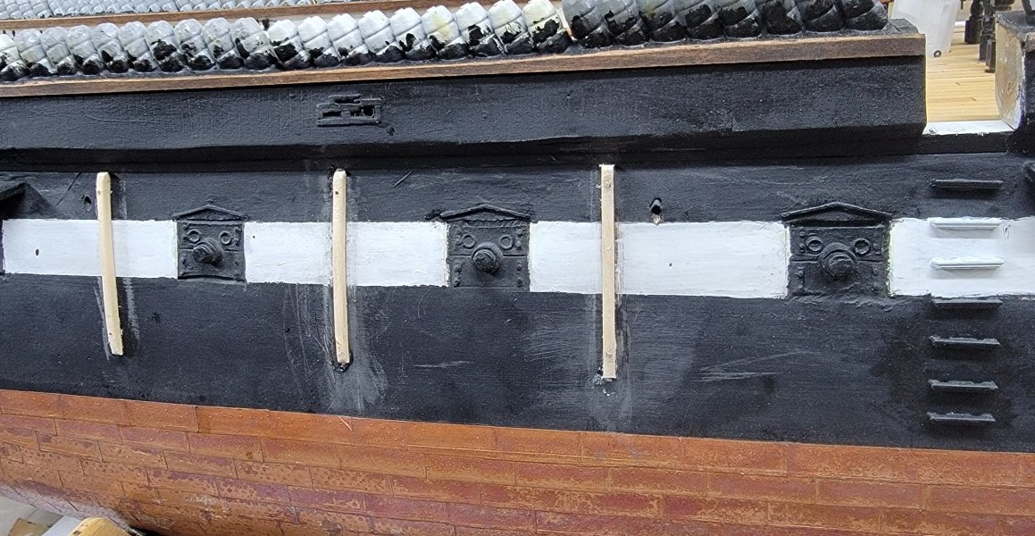
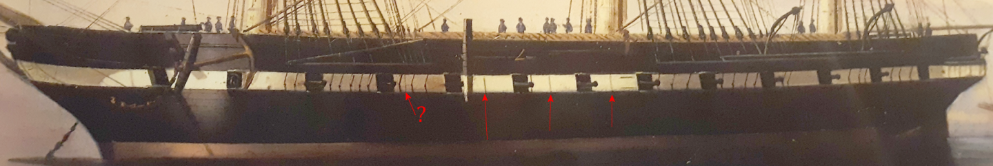
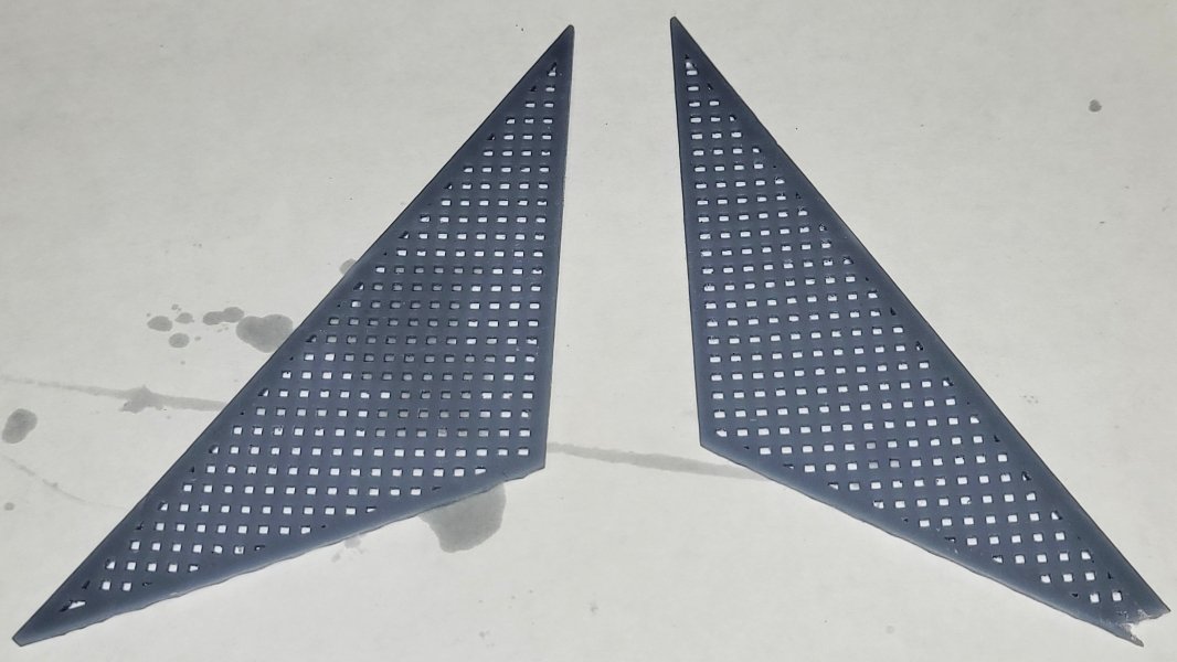
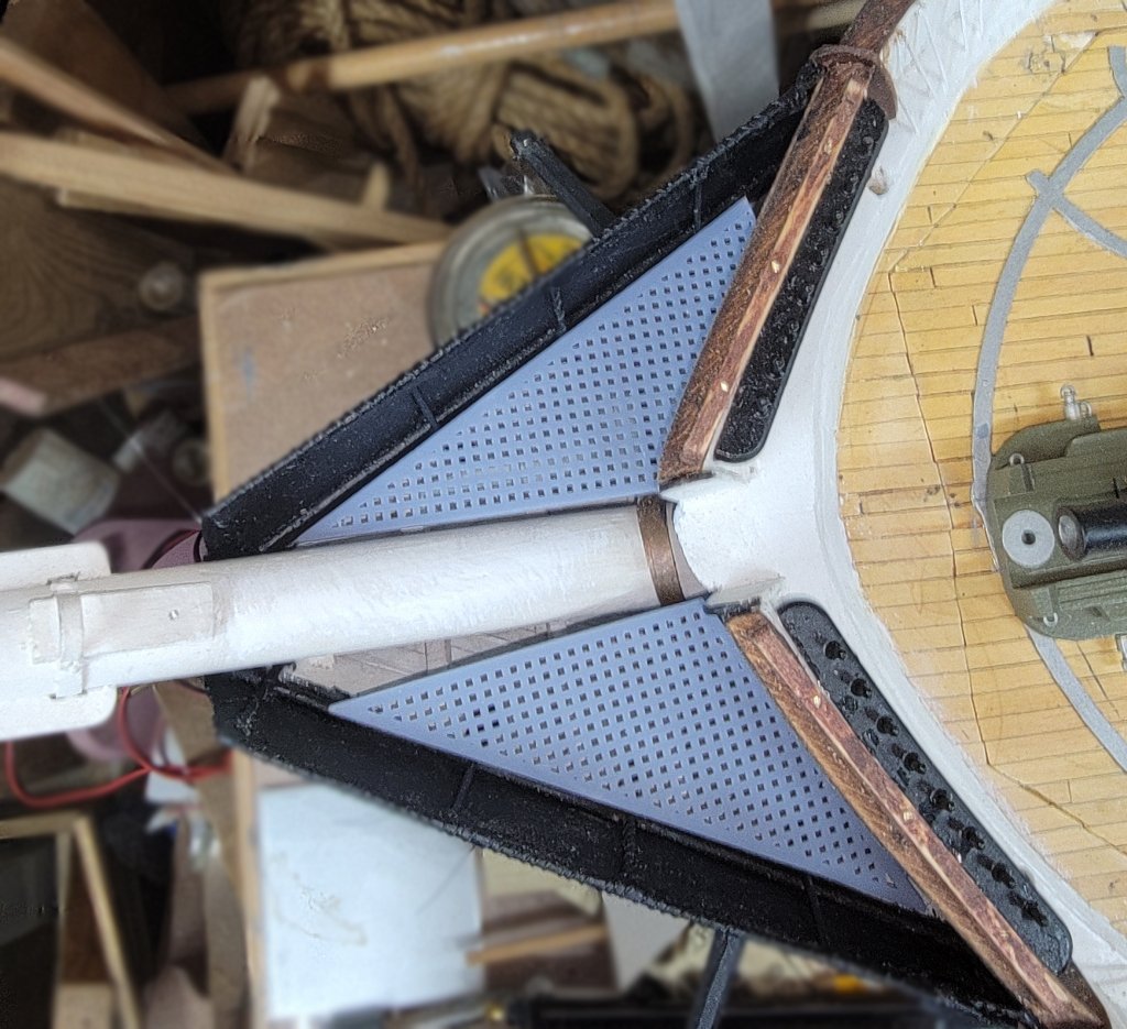
Put ledgers, clamps, cleats, or whatever term is correct in this situation, in the head and made new templates from chipboard From which I modeled and printed new grates.These had a tendency to try to curl, so I attached wood strips to the underside to resist that. They then got primed and painted. There's vertical rub rails on the hull's side. In the 1856 portrait, I con only verify 3 at the main hatch, though more show up in photos from 1879 on, when she carried more boats as a training ship. I'm only adding the three per side I can verify. These were cut to shape to fit the hull, rather than try to spring a straight stick into place, and pinned with 1/16" brass rod; then they got some quick paint. The hull will get a proper paint job just before the chain-plates get installed.

- 553 replies
-
- 2
-
-
- sloop of war
- constellation
- (and 3 more)
-
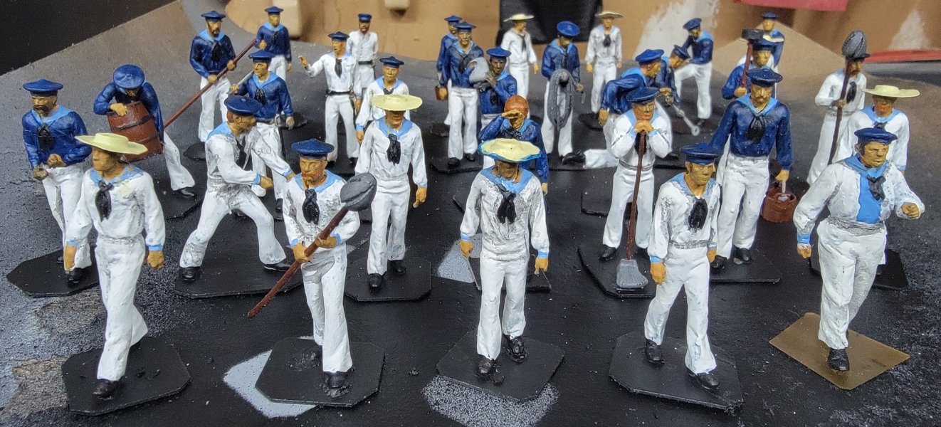
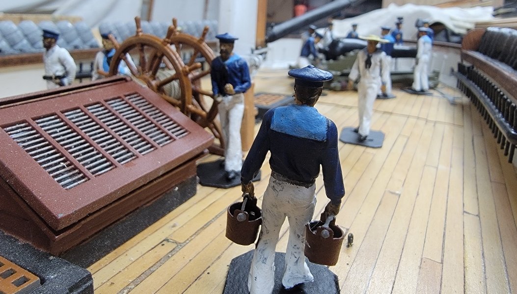
The crew got some touch up, and I tried a "wash" on them which wasn't all I hoped it would be, but I kept it and gave the a couple of coats of clear-coat. Ivan's blue uniform was certainly slimming, he's looking quite Stan Laurel-ish in white. I made a pattern for the head gratings from chip-board, scanned it and used the image to make 3D models. Went away for the weekend, and printed them when I got home. I need to install cleats (like seat cleats in a boat) for them to sit on along the spray-screens and hull. Then I can more accurately see how the shape may need adjusting, which may mean printing again, which didn't use much resin, but did take 4 hours.
- 553 replies
-
- 1
-
-
- sloop of war
- constellation
- (and 3 more)
-
3D Naval Guns 1850s ~ 1870s
JerryTodd replied to JerryTodd's topic in CAD and 3D Modelling/Drafting Plans with Software
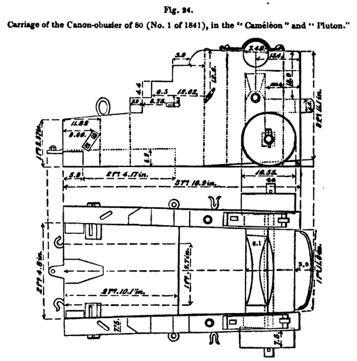
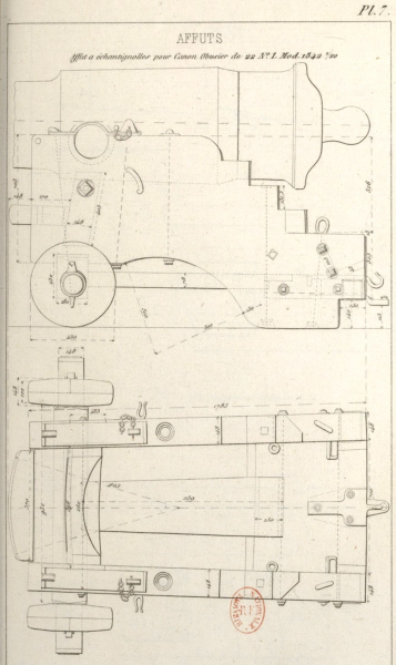
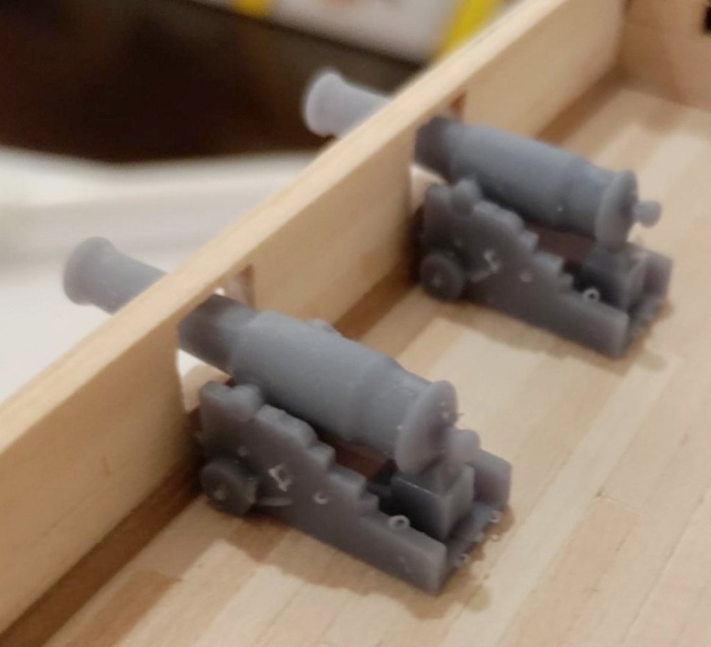
Took three tries before the guns printed well in 1:100. Using thicker supports seemed to do the trick. I went back to the first version I started of this gun, with the taller carriage, to finish it. I used plate #7 of LaFay's, which had measurements, rather than the model plans I had used. Both are modeled in 1:36 scale and posted on Thingiverse. Two of the delivered guns sitting on the model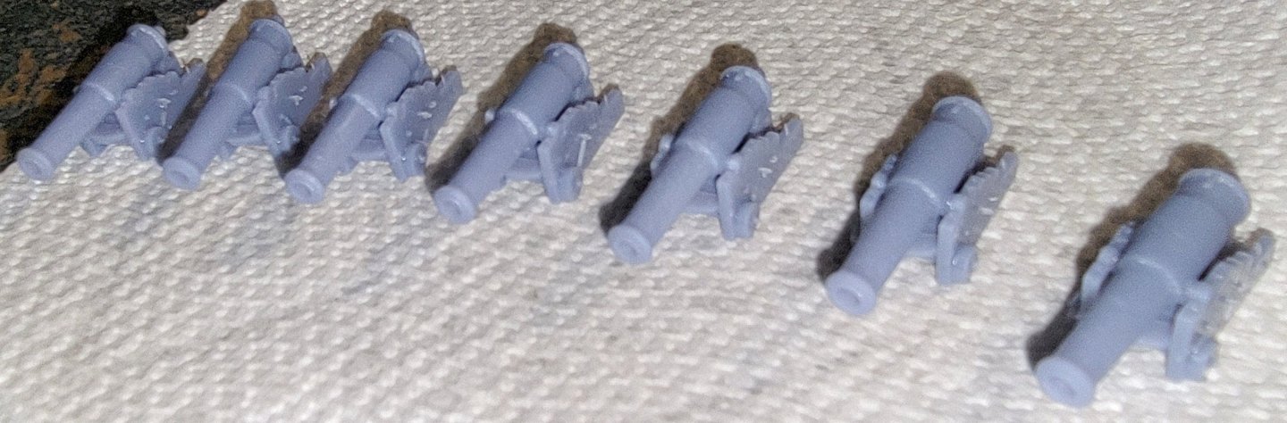
-
3D Naval Guns 1850s ~ 1870s
JerryTodd replied to JerryTodd's topic in CAD and 3D Modelling/Drafting Plans with Software
le canon est complet! Loaded in the slicer, re-scaled to 1:100, copied to make 7 tubes and carriages, sliced and sent to the printer. Fingers are crossed!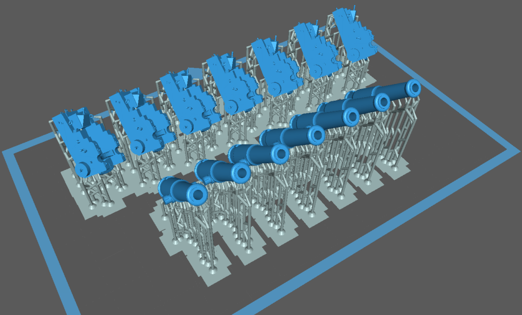
-
3D Naval Guns 1850s ~ 1870s
JerryTodd replied to JerryTodd's topic in CAD and 3D Modelling/Drafting Plans with Software
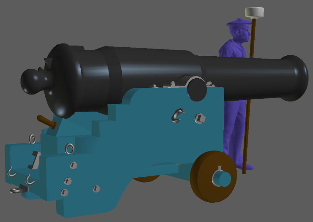
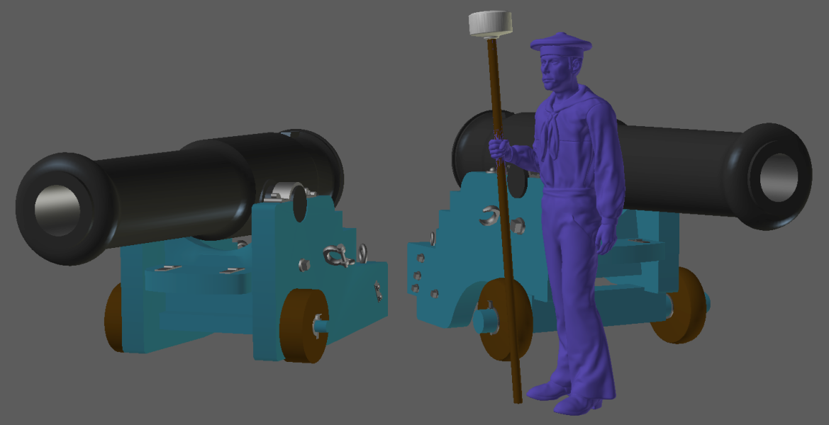
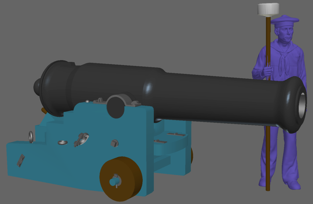
I got this far on it before I had to do other things today and tomorrow. Comparing the tube height to the sailor figure, this carriage is definitely a better match for the model it will be living on. I'm modeling it in 1:36 scale, but I'm printing them in 1:100. Besides what I print for my friend building the model, it'll get posted on Thingiverse when it's done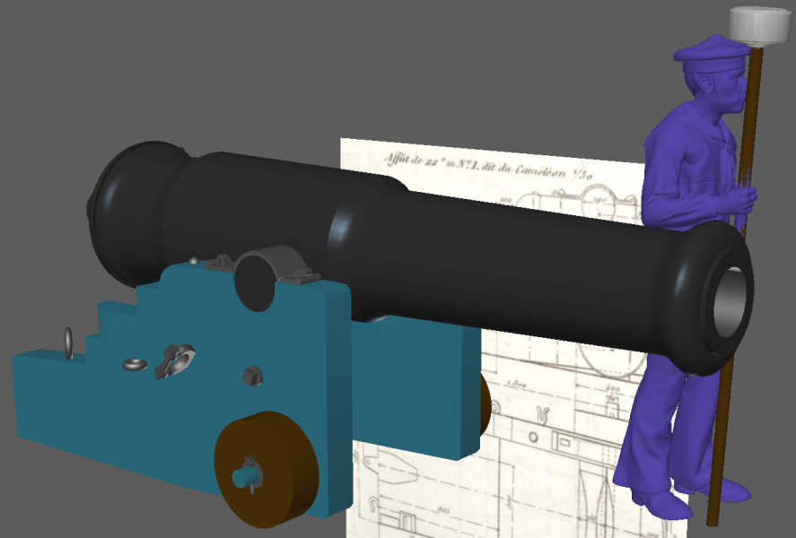
-
3D Naval Guns 1850s ~ 1870s
JerryTodd replied to JerryTodd's topic in CAD and 3D Modelling/Drafting Plans with Software
I found I could download the PDF of Lafay, so now I have a reference if another French gun shows up on my inbox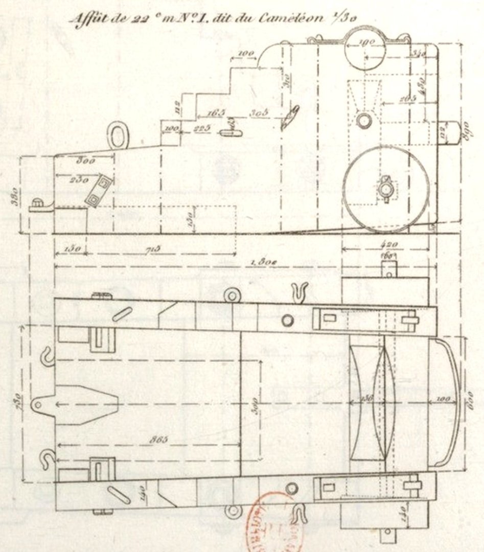
-
3D Naval Guns 1850s ~ 1870s
JerryTodd replied to JerryTodd's topic in CAD and 3D Modelling/Drafting Plans with Software
The Lafay link goes to the same carriage that I made, which I'm thinking is for a smaller gun, abiet very similarly shaped; but Douglas shows... which specifically says is for the gun I'm doing, so I think I'm going that route. Thank you very much Lieste, for pointing out a document I already had