

JerryTodd
-
Posts
788 -
Joined
-
Last visited
Reputation Activity
-

 JerryTodd got a reaction from aviaamator in Constellation 1856 by JerryTodd - 1:36 scale - RADIO - First Class Sloop of War
While I considered what to do about the plug, I found some very nice white cedar while getting something else at the lumber yard, so I began making the lower masts.
Since I had no plans for Constellation's spars specifically, I used several sources for the details, including Spars and Rigging From Nautical Routine, 1849 and Biddlecomb's Art of Rigging, but the best source I found for this 1850's warship was Luce's Textbook of Seamanship which has some very detailed drawings of the rigging of this period.
After drawing the spars full-scale, I cut the cedar to the rough dimensions on a table saw:
I then marked out the details and the taper:
Shaved the taper, then marked the spar to make it 8-sided:
The masts were banded with the same brown paper tape the plug was made from, the hounds and the front fish were made and attached:
The cross-trees and trestle-trees for the lower tops were made along with a rough set of mast caps:
The topmasts were made from the same cedar and in the same manner as the lower masts. Some temporary mast steps were placed inside the plug, a stand made from 3/8" plywood to hold the model up, and some paint went on the lower masts.
By this time I was convinced that glassing the plug and making it the model's hull was the best course to take...
Next: Prepping to glass
-
 JerryTodd got a reaction from CDW in Constellation 1856 by JerryTodd - 1:36 scale - RADIO - First Class Sloop of War
The deck clamp was built up from two layers of pine strips, much the same as the hull's battens. The sub deck would be 3/16" luan plywood with strips glued down on top for the visible decking, so the deck clamp was set down so the finished deck would be flush with the sheer.
The subdeck was cut from the ply and fitted
Then the positions of the hatches and deck furniture marked on it to determine where the deck beams would be needed.
At this point I only had two sources for the ship's spar deck layout; Chapelle's drawing of Constellation from The History of the American Sailing Navy, and model plans of the ship from A.J.Fisher which the people restoring the actual ship told me they were using. The Fisher drawings are of the ship in 1941 and very crude. Chapelle's drawing says they are from the original drawings, but the 1854 drawing of the spar deck was missing from the National Archives. The major differences being the main hatch in 1941 was shaped like a capital I and the galley hatch had a house on it - neither of which are on Chapelle's drawing. I opted to go with Chapelle. Later, I found more information that vindicated my decision.
Down in the hull, straight beams were installed to carry the equipment decks where the radio equipment and sail controls would be mounted. I also decided to step the masts on these decks. The deck beams were laid out to form mast partners and hatch framing. Each beam was cambered and notched to hook under the deck clamp. The subdeck would be epoxied on and sandwhich the beams and the deck clamp all together.
Temporary mast steps were put in to get the mast partners properly aligned, and the subdeck was sawn into 2 inch wide strips so it could conform to both the beams camber and the boat's sheer.
-
 JerryTodd got a reaction from John Allen in Constellation 1856 by JerryTodd - 1:36 scale - RADIO - First Class Sloop of War
While I considered what to do about the plug, I found some very nice white cedar while getting something else at the lumber yard, so I began making the lower masts.
Since I had no plans for Constellation's spars specifically, I used several sources for the details, including Spars and Rigging From Nautical Routine, 1849 and Biddlecomb's Art of Rigging, but the best source I found for this 1850's warship was Luce's Textbook of Seamanship which has some very detailed drawings of the rigging of this period.
After drawing the spars full-scale, I cut the cedar to the rough dimensions on a table saw:
I then marked out the details and the taper:
Shaved the taper, then marked the spar to make it 8-sided:
The masts were banded with the same brown paper tape the plug was made from, the hounds and the front fish were made and attached:
The cross-trees and trestle-trees for the lower tops were made along with a rough set of mast caps:
The topmasts were made from the same cedar and in the same manner as the lower masts. Some temporary mast steps were placed inside the plug, a stand made from 3/8" plywood to hold the model up, and some paint went on the lower masts.
By this time I was convinced that glassing the plug and making it the model's hull was the best course to take...
Next: Prepping to glass
-
JerryTodd got a reaction from John Allen in Constellation 1856 by JerryTodd - 1:36 scale - RADIO - First Class Sloop of War
The deck clamp was built up from two layers of pine strips, much the same as the hull's battens. The sub deck would be 3/16" luan plywood with strips glued down on top for the visible decking, so the deck clamp was set down so the finished deck would be flush with the sheer.
The subdeck was cut from the ply and fitted
Then the positions of the hatches and deck furniture marked on it to determine where the deck beams would be needed.
At this point I only had two sources for the ship's spar deck layout; Chapelle's drawing of Constellation from The History of the American Sailing Navy, and model plans of the ship from A.J.Fisher which the people restoring the actual ship told me they were using. The Fisher drawings are of the ship in 1941 and very crude. Chapelle's drawing says they are from the original drawings, but the 1854 drawing of the spar deck was missing from the National Archives. The major differences being the main hatch in 1941 was shaped like a capital I and the galley hatch had a house on it - neither of which are on Chapelle's drawing. I opted to go with Chapelle. Later, I found more information that vindicated my decision.
Down in the hull, straight beams were installed to carry the equipment decks where the radio equipment and sail controls would be mounted. I also decided to step the masts on these decks. The deck beams were laid out to form mast partners and hatch framing. Each beam was cambered and notched to hook under the deck clamp. The subdeck would be epoxied on and sandwhich the beams and the deck clamp all together.
Temporary mast steps were put in to get the mast partners properly aligned, and the subdeck was sawn into 2 inch wide strips so it could conform to both the beams camber and the boat's sheer.
-
 JerryTodd got a reaction from CaptainSteve in Constellation 1856 by JerryTodd - 1:36 scale - RADIO - First Class Sloop of War
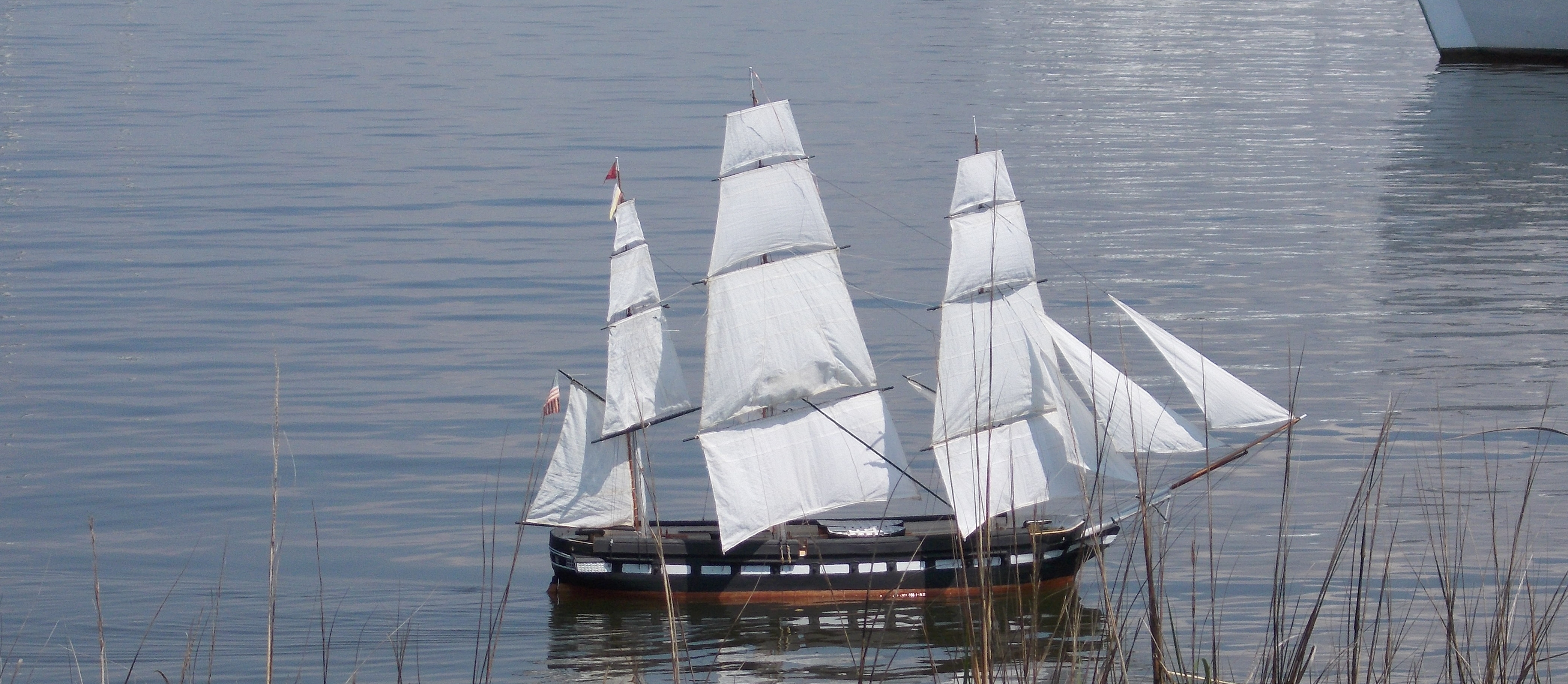
Inspired by a large RC model of the Rattlesnake featured in an issue of Model Ship Builder magazine, I looked around for a subject to built and decided to built the ship in my own back yard, the sloop of war Constellation tied up in Baltimore's Inner Harbor since the mid 1950's.
Some video of Rattlesnake
Constellation was a sloop-of-war, of 22 guns, designed by John Lenthal, and built in 1854 by Gosport Navy Yard at Norfolk, Virginia; the last US warship designed and built to operate under sail alone. For a long time she was believed by many to be the old frigate of 1797, rebuilt and moderized, and that debate has raged in the maritime history community for decades.
Her lines and sail plan were acquired from the National Archives where I got to handle the actual hand drawn documents. I decided to build her as she appeared in a portrait by deSimone when she was in Naples in 1856 and still a new ship.
Her lines were drawn in 1:36 scale, which was perfect, giving a model:
Beam: 13-5/8" (34.713 cm) Length over the rig: 96" (243.84 cm) Width over the rig: 36" (91.44 cm) ~ Main yard w/o stuns'l booms. Length on deck: 61" (154.94 cm) Length between perpendiculars: 59-1/8" (150.178 cm) Draft, without ballast keel: 7" (17.78 cm) With 3-1/2" ballast keel: 10-1/2" (27.94 cm) Height bottom of keel to main truck, without ballast keel: 65" (165.1 cm) With ballast keel: 69" (175.26 cm) Sail Area: 2,807.01 square inches in 17 sails (19.5 sf, 18,109.7 scm, 1.8 sqm)
This log will cover my work on this model since it began in 1999 up to where it is now.
Author's Note: This is a log of how I am building this model, not a guide to how a model such as this ought to be built. It's full of fits and starts, changes of mind, errors, re-do's, more error's, a few mistakes; and somehow, despite all this, it seems to be becoming a working, sailing model that actually looks something like it's namesake. The director of the actual ship recognized it on first sight - I take that as a good sign!
If you're considering taking on a project like this, please, please, don't let this build log deter you - it's not nearly as difficult as I make it seem. Just take away from it that which helps you along, and ignore the rest.
-
JerryTodd got a reaction from aviaamator in Constellation 1856 by JerryTodd - 1:36 scale - RADIO - First Class Sloop of War
Much more regarding the details of why I chose this ship to build; history of the ship; and other items of interest can be found on my web page for this project. This "log" is to replace the one that had been posted here before the forum crashed and lost a lot of data.
Beginning
Having the plans already in the size I wanted saved a lot of time getting started, and I used the Model Ship Builder article as a guide at first. A bit of scrap particle board from a remodeling project was used as a building board. The forms were cut from scrap wood paneling, and the keel was some 1/2" scrap birch plywood from a cabinet I built. This was all stood up by the end of March, 1999.
Then I discovered a book;
William Mowll's Building a Working Model Warship:HMS Warrior, 1860.
Mowll covered his forms with battens instead of planking and covered that with gummed brown paper packing tape over which he applied masking tape to create a plug for making a fiberglass mold. The masking tape was to give the texture of Warrior’s cast iron plating. I happened to have a large roll of the brown tape, and got the idea of using this method to make a plug and cast 3 hulls in glass fiber. I didn't need the masking tape as Constellation wasn't iron plated, I would use the brown tape to impart planking details to the mold.
So, moving forward with this plan, I battened the forms with scrap white pine strips...
...and proceeded to cover that with the brown paper tape creating what would be a plug for a fiber-glass mold.
The tape shrinks a bit when it dries and can be sanded. Once the form was covered diagonally I began applying a second layer in the form of strips to represent planking, gunport lids, and even copper bottom plating - all this detail would be picked up by the mold and imparted to the glass hull when it was laid up. The plug still needed more details, like quarter galleries, but none of the drawings available gave these details, so I had to go digging.
In the meantime we sold the house and bought a small farm where we kept some horses and I commuted 65 miles one-way to work. The plug went into the barn, covered in plastic, and wasn't touched from 2003 till 2008.
Next: Work resumes.
-
JerryTodd got a reaction from John Allen in Constellation 1856 by JerryTodd - 1:36 scale - RADIO - First Class Sloop of War
Work Resumes
So, life went and changed things around a bit. My wife and I went different ways and the farm was sold. I moved into an apartment and the workshop and the plug went into storage. In the late spring of 2008 I bought a house with a 12 x 29 shed that became my workshop, subsequently known as "The Damn Yankee Workshop."
With the shop set up, I began to work on the plug in earnest. Those details needed for the mold still had to be added and the quarter galleries were a big part of that, so that's where I started.
These things didn't need to be very structural as the entire plug would be destroyed in removing it from the mold.
In the mean time I visited the restored vessel and learned some things. The bulwark on the spar deck was actually planked up hammock stanchions. When the ship was being "restored" as a frigate, they took off the hammock irons and tossed them into the bilges, the restoration recovered all but one and reinstalled them.
This changed the shape of the hull for me. Instead of "solid" bulwarks continuing smoothly up to the cap rail, the hull stopped with a cap on top of the waterways, and had these stanchions mounted on top of that cap and covered with wainscoting. So, I cut the plug down to the lower level at the top of the waterways.
The whole idea of the plug being destroyed when the mold was made began to nag at me. There was a chance, a very good chance in my opinion, that the mold might not turn out and the whole thing would be a disaster and a major waste of time and effort.
Next: A Course Change
-
 JerryTodd got a reaction from JerryGreening in Constellation 1856 by JerryTodd - 1:36 scale - RADIO - First Class Sloop of War
While I considered what to do about the plug, I found some very nice white cedar while getting something else at the lumber yard, so I began making the lower masts.
Since I had no plans for Constellation's spars specifically, I used several sources for the details, including Spars and Rigging From Nautical Routine, 1849 and Biddlecomb's Art of Rigging, but the best source I found for this 1850's warship was Luce's Textbook of Seamanship which has some very detailed drawings of the rigging of this period.
After drawing the spars full-scale, I cut the cedar to the rough dimensions on a table saw:
I then marked out the details and the taper:
Shaved the taper, then marked the spar to make it 8-sided:
The masts were banded with the same brown paper tape the plug was made from, the hounds and the front fish were made and attached:
The cross-trees and trestle-trees for the lower tops were made along with a rough set of mast caps:
The topmasts were made from the same cedar and in the same manner as the lower masts. Some temporary mast steps were placed inside the plug, a stand made from 3/8" plywood to hold the model up, and some paint went on the lower masts.
By this time I was convinced that glassing the plug and making it the model's hull was the best course to take...
Next: Prepping to glass
-
JerryTodd got a reaction from JerryGreening in Constellation 1856 by JerryTodd - 1:36 scale - RADIO - First Class Sloop of War
Prepping to Glass - or how not to build a hull.
April 2009
The plug, now "the hull." needed to be prepped in order to be glassed. The card-stock quarter galleries were tossed; the stem knee shaped and tapered; and some of the brown paper detailing removed. The sheer was trued-up and every thing was lightly sanded.
I used the polyester resin available at the local hardware superstore, and laid up one half at a time with 4oz cloth.
After one side set-up, it was trimmed and the other side laid up. The next day that was trimmed, the whole hull sanded, and another coat of resin rolled on:
Once that was set and sanded all the forms were carefully removed. The hull was flimsy with only the battens, paper tape, and some very fine glass cloth:
Glass matting was laid in, one side at a time. Extra resin was poured in while the hull laid on it's side, to try and fill the spaces between the battens. This probably would have been better done with Water Putty, or some other filler that would have filled the space more solidly:
I now had a solid fiberglass hull as the matting made it very rigid.
This is NOT a good way to make a hull for an RC boat. The original plan, before I was distracted by Mowill's book, was the way I should have gone from the start; wood planking on forms, covered with glass and resined inside. If you're following this with the idea of doing one yourself, learn from my mistakes - look at how I built the hull for my Macedonian.
Next: Deck Framing
-
 JerryTodd got a reaction from Krelis in Constellation 1856 by JerryTodd - 1:36 scale - RADIO - First Class Sloop of War
Prepping to Glass - or how not to build a hull.
April 2009
The plug, now "the hull." needed to be prepped in order to be glassed. The card-stock quarter galleries were tossed; the stem knee shaped and tapered; and some of the brown paper detailing removed. The sheer was trued-up and every thing was lightly sanded.
I used the polyester resin available at the local hardware superstore, and laid up one half at a time with 4oz cloth.
After one side set-up, it was trimmed and the other side laid up. The next day that was trimmed, the whole hull sanded, and another coat of resin rolled on:
Once that was set and sanded all the forms were carefully removed. The hull was flimsy with only the battens, paper tape, and some very fine glass cloth:
Glass matting was laid in, one side at a time. Extra resin was poured in while the hull laid on it's side, to try and fill the spaces between the battens. This probably would have been better done with Water Putty, or some other filler that would have filled the space more solidly:
I now had a solid fiberglass hull as the matting made it very rigid.
This is NOT a good way to make a hull for an RC boat. The original plan, before I was distracted by Mowill's book, was the way I should have gone from the start; wood planking on forms, covered with glass and resined inside. If you're following this with the idea of doing one yourself, learn from my mistakes - look at how I built the hull for my Macedonian.
Next: Deck Framing
-
JerryTodd got a reaction from CaptainSteve in Constellation 1856 by JerryTodd - 1:36 scale - RADIO - First Class Sloop of War
While I considered what to do about the plug, I found some very nice white cedar while getting something else at the lumber yard, so I began making the lower masts.
Since I had no plans for Constellation's spars specifically, I used several sources for the details, including Spars and Rigging From Nautical Routine, 1849 and Biddlecomb's Art of Rigging, but the best source I found for this 1850's warship was Luce's Textbook of Seamanship which has some very detailed drawings of the rigging of this period.
After drawing the spars full-scale, I cut the cedar to the rough dimensions on a table saw:
I then marked out the details and the taper:
Shaved the taper, then marked the spar to make it 8-sided:
The masts were banded with the same brown paper tape the plug was made from, the hounds and the front fish were made and attached:
The cross-trees and trestle-trees for the lower tops were made along with a rough set of mast caps:
The topmasts were made from the same cedar and in the same manner as the lower masts. Some temporary mast steps were placed inside the plug, a stand made from 3/8" plywood to hold the model up, and some paint went on the lower masts.
By this time I was convinced that glassing the plug and making it the model's hull was the best course to take...
Next: Prepping to glass
-
JerryTodd got a reaction from John Allen in Constellation 1856 by JerryTodd - 1:36 scale - RADIO - First Class Sloop of War
Much more regarding the details of why I chose this ship to build; history of the ship; and other items of interest can be found on my web page for this project. This "log" is to replace the one that had been posted here before the forum crashed and lost a lot of data.
Beginning
Having the plans already in the size I wanted saved a lot of time getting started, and I used the Model Ship Builder article as a guide at first. A bit of scrap particle board from a remodeling project was used as a building board. The forms were cut from scrap wood paneling, and the keel was some 1/2" scrap birch plywood from a cabinet I built. This was all stood up by the end of March, 1999.
Then I discovered a book;
William Mowll's Building a Working Model Warship:HMS Warrior, 1860.
Mowll covered his forms with battens instead of planking and covered that with gummed brown paper packing tape over which he applied masking tape to create a plug for making a fiberglass mold. The masking tape was to give the texture of Warrior’s cast iron plating. I happened to have a large roll of the brown tape, and got the idea of using this method to make a plug and cast 3 hulls in glass fiber. I didn't need the masking tape as Constellation wasn't iron plated, I would use the brown tape to impart planking details to the mold.
So, moving forward with this plan, I battened the forms with scrap white pine strips...
...and proceeded to cover that with the brown paper tape creating what would be a plug for a fiber-glass mold.
The tape shrinks a bit when it dries and can be sanded. Once the form was covered diagonally I began applying a second layer in the form of strips to represent planking, gunport lids, and even copper bottom plating - all this detail would be picked up by the mold and imparted to the glass hull when it was laid up. The plug still needed more details, like quarter galleries, but none of the drawings available gave these details, so I had to go digging.
In the meantime we sold the house and bought a small farm where we kept some horses and I commuted 65 miles one-way to work. The plug went into the barn, covered in plastic, and wasn't touched from 2003 till 2008.
Next: Work resumes.
-
 JerryTodd got a reaction from qwerty2008 in Constellation 1856 by JerryTodd - 1:36 scale - RADIO - First Class Sloop of War
Inspired by a large RC model of the Rattlesnake featured in an issue of Model Ship Builder magazine, I looked around for a subject to built and decided to built the ship in my own back yard, the sloop of war Constellation tied up in Baltimore's Inner Harbor since the mid 1950's.
Some video of Rattlesnake
Constellation was a sloop-of-war, of 22 guns, designed by John Lenthal, and built in 1854 by Gosport Navy Yard at Norfolk, Virginia; the last US warship designed and built to operate under sail alone. For a long time she was believed by many to be the old frigate of 1797, rebuilt and moderized, and that debate has raged in the maritime history community for decades.
Her lines and sail plan were acquired from the National Archives where I got to handle the actual hand drawn documents. I decided to build her as she appeared in a portrait by deSimone when she was in Naples in 1856 and still a new ship.
Her lines were drawn in 1:36 scale, which was perfect, giving a model:
Beam: 13-5/8" (34.713 cm) Length over the rig: 96" (243.84 cm) Width over the rig: 36" (91.44 cm) ~ Main yard w/o stuns'l booms. Length on deck: 61" (154.94 cm) Length between perpendiculars: 59-1/8" (150.178 cm) Draft, without ballast keel: 7" (17.78 cm) With 3-1/2" ballast keel: 10-1/2" (27.94 cm) Height bottom of keel to main truck, without ballast keel: 65" (165.1 cm) With ballast keel: 69" (175.26 cm) Sail Area: 2,807.01 square inches in 17 sails (19.5 sf, 18,109.7 scm, 1.8 sqm)
This log will cover my work on this model since it began in 1999 up to where it is now.
Author's Note: This is a log of how I am building this model, not a guide to how a model such as this ought to be built. It's full of fits and starts, changes of mind, errors, re-do's, more error's, a few mistakes; and somehow, despite all this, it seems to be becoming a working, sailing model that actually looks something like it's namesake. The director of the actual ship recognized it on first sight - I take that as a good sign!
If you're considering taking on a project like this, please, please, don't let this build log deter you - it's not nearly as difficult as I make it seem. Just take away from it that which helps you along, and ignore the rest.
-
 JerryTodd got a reaction from Chuck in Constellation 1856 by JerryTodd - 1:36 scale - RADIO - First Class Sloop of War
Inspired by a large RC model of the Rattlesnake featured in an issue of Model Ship Builder magazine, I looked around for a subject to built and decided to built the ship in my own back yard, the sloop of war Constellation tied up in Baltimore's Inner Harbor since the mid 1950's.
Some video of Rattlesnake
Constellation was a sloop-of-war, of 22 guns, designed by John Lenthal, and built in 1854 by Gosport Navy Yard at Norfolk, Virginia; the last US warship designed and built to operate under sail alone. For a long time she was believed by many to be the old frigate of 1797, rebuilt and moderized, and that debate has raged in the maritime history community for decades.
Her lines and sail plan were acquired from the National Archives where I got to handle the actual hand drawn documents. I decided to build her as she appeared in a portrait by deSimone when she was in Naples in 1856 and still a new ship.
Her lines were drawn in 1:36 scale, which was perfect, giving a model:
Beam: 13-5/8" (34.713 cm) Length over the rig: 96" (243.84 cm) Width over the rig: 36" (91.44 cm) ~ Main yard w/o stuns'l booms. Length on deck: 61" (154.94 cm) Length between perpendiculars: 59-1/8" (150.178 cm) Draft, without ballast keel: 7" (17.78 cm) With 3-1/2" ballast keel: 10-1/2" (27.94 cm) Height bottom of keel to main truck, without ballast keel: 65" (165.1 cm) With ballast keel: 69" (175.26 cm) Sail Area: 2,807.01 square inches in 17 sails (19.5 sf, 18,109.7 scm, 1.8 sqm)
This log will cover my work on this model since it began in 1999 up to where it is now.
Author's Note: This is a log of how I am building this model, not a guide to how a model such as this ought to be built. It's full of fits and starts, changes of mind, errors, re-do's, more error's, a few mistakes; and somehow, despite all this, it seems to be becoming a working, sailing model that actually looks something like it's namesake. The director of the actual ship recognized it on first sight - I take that as a good sign!
If you're considering taking on a project like this, please, please, don't let this build log deter you - it's not nearly as difficult as I make it seem. Just take away from it that which helps you along, and ignore the rest.
-
 JerryTodd got a reaction from Cap'n Rat Fink in R/C ...WHAT TYPE OF GLUE SHOULD BE USED???
I use Tightbond III for wood-to-wood joints, and epoxy everywhere else.
-
 JerryTodd got a reaction from avsjerome2003 in R/C ...WHAT TYPE OF GLUE SHOULD BE USED???
I use Tightbond III for wood-to-wood joints, and epoxy everywhere else.
-
JerryTodd got a reaction from qwerty2008 in R/C ...WHAT TYPE OF GLUE SHOULD BE USED???
I use Tightbond III for wood-to-wood joints, and epoxy everywhere else.
-
JerryTodd got a reaction from qwerty2008 in Byzantium by qwerty2008 - Scale 1:20 - RADIO - based on the Pride of Baltimore
BTWY: You should resin the inside thoroughly before attaching anything inside the hull. Deck clamp, mast steps, framing, etc can all be epoxied in after, but if resined after attachment, there's a place for water to get in. If water gets in, even a small amount, it will swell the wood causing joints to open, the glass to separate, and make more places for water to get in.
Holes in the hull, for prop shafts and the like, ought to be over sized, filled with epoxy and redrilled to the correct smaller size to prevent any wood from being exposed.
You might consider painting bare wood with Ethylene Glycol (automotive antifreeze - not Propylene Glycol). Glycol soaks into the wood and crystallizes which doesn't allow in water or mold which causes rot. All my models get this treatment. Allow it dry thoroughly and then resin it. If you look close you'll see the wood has little sparkles in it because of the crystals. A lot of wood objects recovered from shipwrecks are preserved this way it keeps out water without shrinkage. Be very sure to follow the safety precautions on the container, I had a neighbor whose dog lapped up a puddle of it from a leaking bottle and it later died as a result - they thought it was rabid until it was tested.
-
JerryTodd got a reaction from qwerty2008 in Byzantium by qwerty2008 - Scale 1:20 - RADIO - based on the Pride of Baltimore
That's a lot of thick ribs in a hull that even at that size, doesn't offer a lot of space. With the outside glassed and the inside given a coat or two of resin, you really only need a couple of those. I kept one to brace the dagger-board trunk, and one for the motor mount. The thing that really made the hull solid was the deck clamp and beams.
What ever you decide to do, remember to make it possible for water to get through fore and aft. Water WILL get in, if only a little, and you want drain holes in any bulkhead so it all goes to the lowest point where it can be pumped and dried out - otherwise you get mold in there and that gets really disgusting really fast. It'll be a very hard hull to reach into and clean.
Consider too keeping the hull as light as you can. That gets more weight onto the removable ballast which is deeper and stiffens the boat more, and allows you to trim her easier with internal ballast. It also makes handling the model a easier if the 20-30 pounds of sailing weight can be shed when she's not sailing.
-
 JerryTodd reacted to captainbob in Malabar Jr by captainbob - FINISHED - 1:48 - 30' gaff rigged yawl
I probably should have painted the hull first, Popeye.
I’m sorry but I did it again. I got carried away building and forgot to take pictures. Anyway I built the cabin furniture so I could put it in before I put on the sub-deck. I put pads on the benches and backs and added a chart on the table. The brown shelf has a step in the middle and another on the cabin deck.
That’s it for now.
Bob
-
 JerryTodd got a reaction from mtaylor in Licorne by mtaylor - 3/16" scale - POF - TERMINATED LOG
I'm sorry, but every time I look at the lines of a French frigate the rap song "I like Big Butts" pops into my head. I can't figure out why.
Happy Birthday
-
JerryTodd reacted to EdT in HMS Naiad 1797 by EdT - FINISHED - 1:60 - 38-gun frigate
1:60 HMS Naiad 1797
Part 180– Finishing the Quarter Gallery
In these last phases of construction some of the items are small and the descriptions short – like this one.
The starboard quarter gallery has been worked and reworked quite a bit as I have deciphered its construction. The last remaining issue was the enclosure atop the upper finishing. My original interpretation of this is shown in the first picture.
I was never satisfied with this arrangement. First, the enclosure is too low based on the original sheer draft. Also, the aft end of it is unsupported and open across the back. Fixing this has been on my “to-do” list for some time.
On ships where the scallops at the ends of the taffrail are convex, there is sufficient height for the enclosure to butt against the taffrail. On the Naiad draft, these scallops are clearly concave, so at the end of the enclosure the cap rail on the taffrail is lower than the top of the enclosure. After quite a bit of searching, I finally found a reasonable reference showing a comparable configuration in John Franklins model of Egmont in the NMM. I replaced the enclosure shown above with the modified version shown below.
In this construction, an athwartship section is installed to meet the height of the side enclosure at the correct height. This seems a logical solution. The enclosure acted as a cistern, undoubtedly lead lined, that provided water the toilet facilities in the quarter gallery, so with the addition of the aft section, a level barrier is provided.
Here is another view.
In this construction the height of the enclosure is at the height of the sheer rail as shown on the drafts and the back section completes the basin enclosure at that height - a much better solution.
Ed
-
JerryTodd reacted to EdT in HMS Naiad 1797 by EdT - FINISHED - 1:60 - 38-gun frigate
1:60 HMS Naiad 1797
Part 179– Gun Port Lids
Before attacking the port lids, I had some rework to attend to. The t-plates installed under the channels were initially made too curved. Although I had drawn these correctly, I had a sketch from a book in my mind when I made them and they ended up too curved. To fix these, the channels had to be removed and each one of the plates bent straight below the angled break at the top. A minor detail perhaps, but I feel better. The corrected versions are shown below.
The next picture shows the ironwork for the hinges, The straps were photo-etched and the pintles fabricated from copper wire and tubing.
The pintles were silver soldered. The next picture shows hinges being fitted to one of the port lids.
After bending the strap down over the hinge pin, the strap is inverted so the bent over piece is in back, where it will be secured by the top through bolt. The straps are bolted though using copper wire that is peened over to hold the straps in place. There is a small ringbolt shackle in the lowest hole through the strap.
The next picture shows the three aft lids installed. There are three aft and two forward.
The next picture shows the two forward lids before the copper was blackened.
The next picture shows the blackened forward lids.
The last picture shows the three lids aft. This picture really highlights the difference in the sheer of the outboard planking versus the flatter line of the upper deck as reflected by the port heights.
The contracts specified shackles on the lids but did not require the rigging or the holes and sleeves through the side. I eventually installed the sleeves.
Ed
-
JerryTodd reacted to EdT in HMS Naiad 1797 by EdT - FINISHED - 1:60 - 38-gun frigate
1:60 HMS Naiad 1797
Part 177– Port Side, Lower Stern
At the time of the “Great Crash” I was working on the unplanked port side of the model and anticipating completion of the entire model within weeks. It eventually took longer, perhaps without the pressure to keep posting – or perhaps it was resisting crossing the finish line.
Anyway, the first picture shows the two additional ribbands installed – one at the height of the wale and the second at the height of the sheer rail. In this picture the planksheer along the waist and the roughtree rail along the topsides of the quarter deck are also in place.
The next picture shows a closer view pf the planksheer and the gangways installed along the waist. The tops of these decked walkways is flush with the tops of the planksheers.
Part of the final work on the port side was to locate and insert all the missing bolts that were left uninstalled during work on the knees, spirketing, and other internal members that bolt through the hull.
The next picture shows a closer view of the port gangway and one of the ladders into the waist.
Only the basic structure of the quarter gallery on the port side was installed. This included the stools, the rim with its stanchions and the upper and lower finishings. The next picture was taken after bolting in the lower finishing on the port side with the model inverted.
While in this position, the final applications of wax finish were applied to the lower stern and the lower hull framing.
The next picture shows work on the lower parts of the starboard quarter gallery that were also installed at this time.
In the next picture the model has been righted and all of the lower parts of the quarter gallery are in place.
Ed
-
JerryTodd got a reaction from qwerty2008 in Byzantium by qwerty2008 - Scale 1:20 - RADIO - based on the Pride of Baltimore
This seemed the quickest way to get the spar dimensions to you...