


mspringer
-
Posts
39 -
Joined
-
Last visited
Reputation Activity
-

 mspringer got a reaction from Bill Morrison in HMS Royal William by KeithW - Euromodel - 1/72
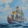
Glad to see another Royal William started. I've always wanted to add one of these to my stash so I'll pull up a chair. I'll be interested to hear how useful the "interpretive information" on the Euromodel site is. Some of it looks good.
I also like your workroom setup...very functional.
Enjoy!
Mark
-
 mspringer reacted to modeller_masa in OcCre HMS Victory Limited edition
Due to the simplified hull, it looks like the easiest HMS Victory kit under 1/90 scale in my opinion. Hull fairing and planking are really big hurdle for beginners. I'm glad more companies release new kits.
-
 mspringer got a reaction from BETAQDAVE in tips on building plastic tall ships
I have "How to Build Plastic Ship Models" by Les Wilkins. It's pretty old but you can still buy used copies through Amazon, although they are a bit pricey. Good luck.
-
mspringer reacted to NenadM in Cutty Sark by NenadM
Thank you all, dear friends, for your intrest in my experiments.
I am afraid I shall not be able to spent more time than I wish with Her Majesty for couple of reasons (I think I mentioned that early)
Princes definitely have got employment certificate in one hospital in Germany for her specialization in anesthezy, and she is here at home only next 2-3 months. Having in mind that Hothead is also here at home couple of months, we all just want to spent as much is possible quality time together. "Rhea the beast" also demands her time, my job also ... my social activities are reduced for next couple of months also, and my hobby...
Also, cataract grows and make me some dificulties working with thiney pieces last two months. Operation is sheduled at the end of February, so this dificulty will be solved.
But I am still here on MSW, lookling what is new every day
"Big Brother is watching you"
-
mspringer reacted to NenadM in Cutty Sark by NenadM
Hello to everybody !!!
At first i want to thank you for your kind care and support
There are several reasons I did not post a while.
At first - puppy is demanding some of my free time, and if she is alone almost all day, I feel she is unhappy if I at the evening go down to workshop and left her alone again. Workshop is for now forbidden space for her for many reasons. Last couple of days I tried to test her, spending some hours in workshop working on my side "play-project" inspired by Chinese Ivory Balls
igranje.mp4
And test run well, so I think soon I will be back to Her Majesty. Rhea is 7 months old now, and she sleep when I am down in workshop.
The second - some extra time I had to spend in office, some extra time visiting doctors, and I want badly to spend some time more with my daughter before she left Serbia forever at Summer/Autumn. My cataract is on early stage, so eventually surgery is planed at February 2018 with further medical consultations. Some other medical research are running through (nothing serious), so my free time drop by drop - gone
The third - After almost two years my Admiral passed, I entered to particular complicated stage of my personal life starting some kind of relationship, also time demanding ...
The fourth - to admit - sometime I am just lazy, and still thinking how to resolve my boats
I really hope to return soon
-
mspringer reacted to NenadM in Cutty Sark by NenadM
Hello to all!
Still thinking ...
After a couple of unsuccessfull tests, not worth to be posted, I am a bit more close to solution with solid body boats.
My sweet beast is still a demanding one, and I am so delighted and excited with her character, personality, frendly attitude and intelegence. Much more I can imagine. She is 5 months old now, with weight growing over 20 kg, and herart and love I just can not describe with words.
Still a baby, but really smart and sweet one, making every of my day nice and shiney
I hope that I'll be able to show some progress soon
In mean time, cheers to everybody!
-
mspringer reacted to NenadM in Cutty Sark by NenadM
Somehow, even I had mini holliday from dec. 28th until jan 10th which I spent mainly with kids at home, my free time slided from my hands. Days full of everything, extreme cold with extreme low outside temperature comparing to average ( full week with max -10°C to -17°C ) snow 40cm, different homeworks and office works last few days, and - I hate winter! Gas and coal consumotion for heating house was also extreme.
Every day I was thinking about making new plug, which do not have to last more than a hour of work, but, it seems that low temperature made empthy my energy resources. Of course, my little sweet beast which doubled her size for a month, demand some time for her. Her learning process goes well, new command almost solved (lay down). Also it seems She starts to love brushing her hair ! And She is crazy loveing to be and to play in snow. Playing with Her, I forced Her to run in yard making snowballs and hitting it in yard with apport command. Of course, She can not find snowball, but She was very happy to run throught snow and to digg it. Yesterday She brought frozen snowball I have hitted couple of days before, which She found by Her nose, smelt it and digged under snow! Really smart kid!
Anyhow, I hope to procceed soon with Her Majesty's boats. Even one of them. In meantime I was thinking about avaliable material which to use for ribs and planks, still without final decision
-
mspringer reacted to EdT in Young America 1853 by EdT - FINISHED - extreme clipper
Young America - extreme clipper 1853
Part 192 – More on Tops
The holiday season is a time for reflection and I have been thinking about the work ahead on YA in the New Year and beyond. One of the approaching tasks is to finish the dust case that was started in an earlier post. This project always gets me thinking about the size of the model. The first photo, showing the drawing of the enormous fore yard attached to the mast, is not nearly as scary as it is in real life, but gives some appreciation of the final model size.
The yard is 82' long (~14" actual), just 7' shorter than the entire lower mast from step to cap – and without studding sail booms. Even with all my familiarity with the drafting, it was somewhat shocking.
The height of the model is another issue. The next picture was taken using a Christmas gift – a new tripod that can crank up to 7' in height.
This will be needed for the rigging photos. A leg of the old tripod may be seen in the picture. So much for reflections on model size.
Some questions arose on the fabrication of the tops after the last post. The steps are many, so I will refrain from describing everything here, except to answer some questions. In the first picture the distance between index holes is being measured so the crosstree can be drilled to match the index holes on the drawing.
The aft tree has already been drilled and pinned in place on the drawing. With the crosstrees in place the trestletrees were marked and the mortises cut, one at a time. In the next picture the forward tree has been removed to check the first mortises.
After the structure was assembled, the bending pattern used for the rim, was used to mark the inner line of the rim on the structure.
In the next picture the half-laps on the cross and trestle trees have been cut, the structure has been located using pins, the rim has been pinned in place, and a chisel is being used to mark the lines of the mortises to be cut in the rim.
After fitting the joints, the rim was glued to the trees and all the excess ends were trimmed back. The iron rim plates were then attached as described earlier.
There was a question on the slotting of the rim to fit the deadeye straps. The next picture shows this being done using a jewelers saw.
The holes are too small to be filed. The saw works well. It does take some contortions to fit the saw to the threaded blade and to reverse it so the cut is always downward on the plate. This keeps it from peeling off.
There is a cap over the forward part of the rim, covering the plank ends and also the joint at the forward end of the trestletrees. This was cut from a single piece of wood and is shown in the next picture being finish sanded.
In this picture some planking has been installed. These were installed over the lubbers hole to ensure a straight line once the lubber hole sections were cut out. The next picture shows the three tops planked.
The holes in the fairlead planks were drilled using the x-y table on the mill to set the spacing. I spent quite a lot of time this week making sure there were sufficient holes in each top. This required reviewing the entire running rigging list of roughly 400 lines. Each hole is allocated to a specific line – generally buntlines, leech lines, clue lines, upper sail sheets and some jib lines. Six yards on each mast add up. The line numbers for the mizzen top may be seen in the lower right of the photo. As a result of the review, I added holes at the forward end of each top. The fore and main tops now have 40 holes each and the mizzen 34. There are just a few spare open holes, none in the mizzen top. I mention this because rigging design and checking is consuming a lot of my time, so the modeling progress these days is slow.
The drawing in the last picture shows additional features added to the cap, in this case the mizzen cap. Drawing discrepancies in the pictures, actually revisions were mentioned earlier. Note that blocks are shown on the cap. These are shackled to the cross iron on the cap, so to avoid having to strap the blocks later to the soldered shackles on the installed cap, this will be done before fitting the iron to the cap – a complication in using soldered shackles that requires more rigging checks early in the work – in this case checks of the entire standing and running list. All of this is a great mental exercise.
Happy New Year everyone.
Ed
-
mspringer reacted to NenadM in Cutty Sark by NenadM
Nice feeling to come back
Workshop temporary installed in kitchen where Rhea is
My peacefull helper, tired ( today was Her first day in homeyard playing and running as devil on specific silly Bobtail's way) and sleepy, watching me carefully
Material used: 0,5mm card for ribs and keel, regular 80gr printing paper for planking
So, I cut ribs and glued them... It looks promissing ...
And started planking trying to simulate specific way of planking on CS boats ( plank over plank) ...
But ...
I realized that I did not cut ribs precise enough, and did not glue them precise ...
Ugly
Lesson learned, and some conclusions
Moulding just has to be solid, or ribs have to be lasser cuted. I prefer first option, because I am not able to cut and glue so precise - 0,5 mm mistake left hole or mountain in hull lines. working with solid moulding alow me to install and glue as first layer inner ribs, and planks over it
Planking with paper will be ok if I make nice moulding with soft lines. Keel has to be made of something harder than card.
After glue dry, whole structure is fragile, but strong enough to allow additional works
Of course, my drawings have to be adjusted for new approach
Having in mind that all four boats are very very visible and at the first line of looking, particulary their white color is in contrast to cabin's roofs color, and that I intend to left them opened to half (simillar as I did with hatches), all boats have to be made just - perfect!!!
Wheels in my brain have to turn some more rounds untill final solution
It was nice to play again, never mind it was unsuccessfull
-
mspringer reacted to NenadM in Cutty Sark by NenadM
This little doll obviously will keep me out of shipyard for a whille
A lot of work in office + a lot of work about her (if I do not want my home to stink...)
-
mspringer reacted to NenadM in Cutty Sark by NenadM
Thanks for nice word. I am still here but occupied with so demanding 2 months old baby which eats my shoes and my free time
-
mspringer reacted to _SalD_ in US Brig Syren by _SalD_ – FINISHED - 3/16" scale
Well it was a very productive holiday break. While the wife and daughter were out shopping I got to play. For this post I was going to do it a little differently. Instead of showing all the steps and then the finished product I thought I would present the finished piece first and then show all the steps for those wanting to see what I did (it is rather long).
So ‘Ta-Da’…my longboat. The oars and rudder have not been permanently glued in yet, because I’m trying different arrangements to see which I like best.
Now the steps. Since this was going to be my first attempt at building a boat like this I thought I would make up some cross-section templates from the drawing to help me shape the hull. The exterior of the hull was rough sanded and shaped with a ‘mouse’ sander and the interior was done using my dremel and a high speed cutter. The final sanding and shaping was done with the dremel using a coarse and fine abrasive buff. The sheer profile was marked out on the exterior of the hull and shaped with a drum sander attachment on the dremel. All finish sanding was done by hand.
Instead of installing the center keel next and then the interior ribs on either side of it I decided to leave out the keel and install the ribs for each side as one piece. I decided to do this since the floor boards will be covering the keel and it won’t be seen. The first rib was installed approximately at the center of the boat. Once that rib was set I used a 3/32” wide plastic zip-tie to space the remaining ribs. I saw this method used here on MSW but for the life of me I can’t remember whose log it was. As careful as I was I found that even after soaking the 1/32” square strips for hours with ammonia that they still kink towards the bottom.
While waiting for the glue to dry between ribs I worked on the longboat oars and the ships sweeps. I’ll describe how I did these later on.
Next for some unknown reason, well there was a reason but that’s another long story, I install the keel, stem and stern posts. I would not do this at this point the next time. After staining the interior of the boat the floor boards were placed as described in the instructions. I used sewing pins for spacers between the boards. You need to be careful not to push them through the hull.
The thwart support was added next. I used a drafting divider to mark its location on the ribs. Note that these pieces and the floor boards were all stained prior to gluing them in place.
Next I wanted to see how the longboat would look with red bulwarks and caprail, so I cut out a caprail using some red construction paper and….well the wife and daughter put the nix-e-do to that and I agreed.
The grating and thwarts were done next. The grating was done per the instructions and the thwarts were dressed up a bit by scribing the edges. By some miracle most of the thwarts landed squarely between the ribs. The thwart with the iron strap to support the mast was cut out of the scrap 1/32” thick laser cut sheet. The iron straps were made from blackened copper foil and the belaying pins were ones left over from my Phantom kit. The idea for adding the scribed edges and belaying pins were gotten from Chuck’s Model Shipway’s Longboat kit. So were the split rings and mast step on the floor boards.
The windlass was made per the instructions. I tried to make the shaft octagonal but it came out more roundish. I should have tried to make it round and then it would have come out octagonal for sure.
Moving to the exterior of the boat the caprail and molding below the rail were added next. I used the laser cut caprail with some modifications. The rail provided was a little short, so I needed to cut the end off and add a piece. I apologize that I don’t have any pictures of this because my phone (camera) went dead. After gluing the caprail in place I wasn’t too happy with the outboard side so I sanded it flush to the exterior of the hull and then added a 1/32” square strip to the outside edge. The molding strip was added as per the instructions.
The oar locks, splash panels, knees, and bowsprit step were added next and then the exterior of the hull was painted. Once the paint dried I added the gudgeons and bowsprit iron strap. I also added some pins to the bottom of the keel and the chocks on the gallow bitts to help position the boat. The rudder and tiller were made as per the instructions. I tried to put the pins in the pintles but they were just too small.
-
mspringer reacted to NenadM in Cutty Sark by NenadM
Than you Marc, I ll keep it on mind. For now, I found some solution in laser cutting next week
Tonight I ll start second part of my Shumadia tour vacation, going in middle-south Serbia, to town Krusevac, capital City of Serbia in XIV century, raised by Prince Lazar, famoys ruller who lost his life in Kosovo Battle 1389, where also died Turkish Sultan Murat the 1st. My grand father was born in Krusevac, where from during first world war at age of 16. he was taken from France army to finish school in Paris, where he graduated medicine in Sorbon university. After that, tomorrow, kids and I will go to Trstenik, where my grand mother was born, to visit old monastery Ljubostinja where my grand parents were married. This monastery was raised by Lazar`s wife Milica after his death 1389, at same start of XV century. After Kosovo battle, Milica continues to rule country , and gives her daughter Olivera to Murat`s succesor Bajazit to be his wife. Milica and Olivera were the most powerfull womans in XV century in this part of world
Then maybe spent some time on Cuty pool, visit famous Vrnjacka banja ( spa center with natural hot and cold mineral water), and maybe short trip to visit Maglic fortres, raised in early XIII century during Mongolian wars in XIII century.
After that, in return, I intend to take kids to visit Manasia monastery again, and Smederevo fortres on Danube
-
mspringer reacted to EdT in Young America 1853 by EdT - FINISHED - 1:96 - POB - extreme clipper
Young America 1853 – POB 1:96
Part 12 – Stem/Keel/Sternpost 1
The stem assembly, keel and sternpost on the POB model are virtually identical to their counterparts on the framed model except for scale and the deletion of a few unnecessary internal structural parts. Unlike the framed version that started construction with this work, on the POB model they were made and installed after the hull was shaped.
In keeping with the concept of simpler tools and readily available materials for this version, scale members were all cut from ¾” (4/4) material. For the stem/keel/sternpost, hard maple was used – with pieces selected for straight grain. Becaused of its visible grain pattern I would only use maple where work will be painted or metal sheathed.
The POB model did not require the thickness sander or band saw. Members were sized using circular saws. If ¾” hardwood can be ripped on an available 4” model circular saw, ripping stock to required dimensions is just a matter of setting the rip fence and cutting. On the full-sized (10”) table saw that I used, a different method was adopted. The first picture shows stock for the 16” wide keel about to be ripped off of a piece of 3/4” maple.
Although cutting sized strips away from the rip fence as shown takes a bit more setup time, it is much safer and eliminates damage to small thicknesses left between the fence and the blade. It also avoids having them come out of the saw at high velocity. The blade in the picture is an ultra-thin kerf (.080"), 40-tooth carbide blade that leaves a very clean surface on the strip. The Plexiglas® table insert was specially made for close clearance to this blade. The next picture shows the ripped 16” strip being checked for size.
I usually start with a very small cut into the plank and measure what will be the resulting strip thickness, then adjust the fence if necessary before cutting off the whole strip. This was then repeated for each cut. The ¾” strips were then used to make sections of the keel and the other components.
In the next picture the POB stem pieces are shown on a copy of the pattern sheet.
All were able to be cut from the ¾” inch stock except for the lower stem as shown above. On the original ship this piece would have been cut from a very large piece of compass timber – probably live oak for strength. On this model, two pieces of edge-glued ¾” maple were used. The next picture shows the two pieces used for this being edge glued.
Undarkened Titebond® was used for this to minimize joint visibility, although on this model all this will be covered by metal sheathing. The long straight piece in the picture is being used to make sure the two glued pieces lie flat.
The next picture shows the four stem pieces cut out and ready for fitting. Dashed lines around the patterns show ¾” stock.
The pieces were cut on the scroll saw very close to the pattern lines, then dressed with a file for final fitting – as shown below.
The patterns were left pasted on for all of this work. In the next picture,, the false stem (the members forward of the stem proper) have been fitted and aligned on the drawing.
The false stem pieces are being glued in the next picture.
Alignment is again provided by the drawing. To be continued…
Ed
-
mspringer reacted to augie in USF Confederacy by Augie & Moonbug - FINISHED - Model Shipways - 1:64
Things have been a bit slow in the yard as the chief shipwright, deciding to use as #11 blade as a chisel, added his DNA to the build. No major damage but a painful reminder that it's impossible to do the fiddly bits with bandaged fingers.
However, we did manage to get a start on the foredeck. Here, we've added some coamings, companionways, and a second fife rail. Note the chimney for the stove below. I love that stove, now 80% invisible. But we know it's down there !
-
mspringer reacted to EdT in Young America 1853 by EdT - FINISHED - 1:96 - POB - extreme clipper
Young America 1853 – POB 1:96
Part 10 – Hull Fairing – Method 1
As seen in some of the previous photos, there is quite a bit of wood to be removed from the spacers used in this framing method. It is much like working on a solid lift type hull, but the numerous bulkheads make it very easy to accurately duplicate the original shape by merely removing wood down the each of the bulkheads then finishing it off to a smooth fair surface.
My natural response to this work was to use available carving tools to remove wood between bulkheads, followed by rasping and sanding. This is a good method to use if you have the tools and the ability to keep then razor-sharp. However, although I used this method on the starboard side, I wanted to offer a simpler process, using less expensive tools on the opposite side. That second method will be described in the next part.
The first picture shows shavings being pared off the hull using a shallow curved gouge with hand pressure.
A solid anchoring of the hull is essential to allow two hands for this work. The sharp gouge easily removes thin cross-grain shavings. In the next picture a deeper gouge is being used with a mallet to chip off larger pieces of the extreme bevels near the stern. Again, this requires the hull to be firmly secured.
After paring with the gouges the shape was further smoothed out with fine-cut rasps. The curved rasp in the next picture was used on the concave surfaces.
A flat rasp was used on the convex hull surfaces as shown in the next picture.
The rasps used here are fine-cut Iwasaki® carving rasps. This is not a job for the coarse hardware-store variety. You can pay almost anything for a rasp. These are good quality and reasonably priced. The last step on this side was done with 120-grit sandpaper on Softsander® pads – as shown in the next two pictures.
The rasping and sanding bevel the plywood bulkheads as necessary to leave a smooth surface. This involves trimming only the small side of the plywood shapes. This point is indicated by feel as well as sight.
The above picture shows the finished and unbeveled sides and gives an idea of the amounts of wood to be removed.
This work went pretty fast, taking less than 2 hours for this side of the hull. A second method will be shown on the port side in the next part.
Ed
-
 mspringer got a reaction from billt in tips on building plastic tall ships
Yes, I agree...very expensive. I'll also say that unless you just really want a book to look through, all the content that is contained in the book is covered at some point on this site and is in greater detail than the book. Plus there are quite a few build logs on the Constitution in plastic that are very active at this point that also cover the same material as in the book. But with that said, there is still nothing like holding a real paper book...
-
mspringer reacted to EdT in Young America 1853 by EdT - FINISHED - 1:96 - POB - extreme clipper
Young America 1853 – POB 1:96
Part 3 – Erecting Bulkhead Assemblies
In the full-framed version of the model, frames were plumbed then clamped in place using small wood spacer blocks or later, using ribbands at the planksheer. For this model the bulkheads are glued to their neighbors using wood spacers. The method is basically the same but requires a different clamping method. The first picture shows the device used to clamp the bulkheads for gluing.
The two plywood rectangles fit loosely over the central spine. They are drilled at the same level as the holes shown earlier in each bulkhead. A long, loose-fitting threaded rod is used to tighten the glue joints as each new bulkhead is added and aligned. The next picture shows bulkhead 2 being glued.
The squares are used to align the frame to the maximum breadth line on the shipway plan. The nut on the threaded rod is then tightened to secure the glued joint. The next picture shows more bulkheads added - one at a time.
And so on.
In the above picture the fairness of the deck “beams” is being checked with the metal rule. If the notches over the spine are cut carefully, the line should be precisely fair.
The next picture is a close up of some bulkheads showing the excess spacer material that will need to be removed later.
Note that the station lines on the shipway plan align with the plywood bulkhead at its maximum breadth. When the hull is faired by removing the excess and smoothing the line to over the plywood sections, the hull shape will be precise.
The last picture shows the framing of the forebody almost complete.
Note in this picture that the midship frame and another forward of that are held in alignment throughout this process by squares clamped to the shipway. This prevents the hull shape from twisting as frames are added.
While building up to this point, a number of special attachments were made on some of the bulkheads for mast steps, reinforcements and hold down bolts. I will show some of these in the next part.
Ed
-
mspringer reacted to DORIS in ROYAL CAROLINE 1749 by Doris - 1:40 - CARD
Royal Caroline is finished. Here you can see many pics of the model:
-
mspringer reacted to rafine in Frigate Essex by Rafine - FINISHED - Model Shipways - Kitbashed
DONE!! Essex is now completed. The last item was the lantern kit from Caldercraft that just arrived from the UK. Etched brass with a white metal top and base and brass rod support. A fussy little piece to do, but correct in size and shape.
Essex has now sat for her completion portraits and it is time for some reflection on the past almost two years that I have worked on her:
1) This was a great challenge. Those who have followed along from the beginning will remember that I almost gave up in frustration at the problems that presented themselves. I'm very glad that I didn't. It turned into an enjoyable and rewarding experience. I had my doubts about how things would turn out and some of my fears were realized -- for example, the placement of the quarterdeck gun ports turned out wrong when I did the rigging. This was my fault for not having thought it through well enough when I was making the various structural changes that were required. I thank everyone for kindly not pointing out the errors when they appeared.
2) I will not do another model at this small a scale again. The problems of aging eyes and arthritic hands made some of the very small work and particularly the rigging in very close quarters a pain. This probably also means that this may be the last large complex ship that I will model. My current plan is to stick to smaller vessels in larger scales. Chuck's Cheerful is next.
3) Some words of warning and encouragement to those wishing to build the "new" Essex kit. I have not seen it, but I've read the posts from some who have. If the drawings have not been changed, you will have problems. The drawings have scale issues, inconsistency issues and, according to Sam Cassano, were not his final drawings. Using the AOTS Essex as an additional reference is a help, but care will still be required to make it all work. Having said that, I think that anyone with moderate skills and some experience can turn out a creditable model. I would love to see some logs started, and I would be happy to provide any help that may be desired.
Thanks to all for the interest, the generous thoughts and comments and the help and encouragement throughout this project. It is always appreciated and is what makes this site so great. A special thank you to Sam for all his help and a wish for his good health.
Bob
-
mspringer reacted to Gahm in US Brig Syren by Gahm - Model Shipways
A little update. Things as usual are moving very slowly due to lack of modeling time (what’s new ? ). I finished the first 4 carronade carriages and the first “production” carronade (image 1).
Images 2 a-d show the fabrication of the hinges for the gun barrels. For this I milled a grove into a brass strip and silver soldered a brass tube into the grove. The result is shown in image 2a. To cut hinges from this piece with always the same width I combined my Taig lathe and my rotary tool with flex shaft (in lack of a suitable table saw) to a metal cutting device (see images 2b and c). The resulting hinges are shown in image 2d.
Image 3a and b present the method I used to determine the correct location of the hinges on the carronade carriage. I placed the gun barrel-hinge assembly on the carriage in such a way that the elevation screw was located correctly on the metal fitting and marked the front end of the hinges with masking tape. As a next step I placed the hinges alone nicely centered on the carriage, with the right distance between them and the front end aligned with the masking tape (image 3a). To help with this process I covered the carriage first with further masking tape and a double-sided sticky tape on top of the masking tape. Once aligned satisfactorily I marked the 2 front ends of the hinges on the masking tape, removed every tape with the exception of the tape with the alignment marks and mounted the hinges permanently using these marks (image 3b). Finally the gun barrel was mounted, the elevation adjusted with the elevation screw, and barrel and screw glued in place. The final result is displayed in images 4 and 5. Images 6 and 7 show the first carronade in its final place on my Syren model.
Thomas
Image 1
Image 2
Image 3
Image 4
Image 5
Image 6
Image 7
-
mspringer reacted to Jeronimo in LE BONHOMME RICHARD by Jeronimo - FINISHED
Hi friends,
many thanks for the comments and Likes.
Unfortunately, a picture with three model segments of the BHR is not possible together.
Every model segment is for itself in a seperate glass cabinet / protective bonnet and
stand on different places.
Here, however, some pictures of my private ship model -museum.
Karl
-
mspringer reacted to Jeronimo in LE BONHOMME RICHARD by Jeronimo - FINISHED
Hello friends,
construction end of the model.
Originally, the model was planed with a complete main mast
and complete rigging.
Massive objections and pressure through my admiralty and government
with regard to the enormous size of the display case required an
amendment to the plan.
Karl
T e i l 59 / Ende
-
mspringer reacted to _SalD_ in US Brig Syren by _SalD_ – FINISHED - 3/16" scale
The templates that I cut from Sheet #2 of the drawings worked out very well. I marked the locations of all the gun ports and sweeps and then proceeded to cut and assemble all the pieces. After installing each group of pieces making up the gun ports and sweeps I sanded them down to their rough shape.
After the sweeps were glued and dried I sanded everything down to their final shape. This was a lot of sanding.
For sanding I used my dermal to take off a majority of the material, for the final sanding I used the sanding blocks shown below. I had seen the red blocks in Marsares's Syren build and liked their shape so I purchased two. The 20mm wide sander was very handy for doing the inboard side of the bulwarks, the 40mm wide one was good for doing the outboard side with its rounded surface. The one I made from a cardboard tube with sandpaper taped to it also worked very well for the outboard side. The emery boards and pencil sander I used to clean up the inside of the gun ports.
-
mspringer reacted to _SalD_ in US Brig Syren by _SalD_ – FINISHED - 3/16" scale
I finished placing the two 5/32” wales below the top most wale and the first 1/8” plank below them. I also completed placing the garboard plank and the two 1/8” planks above it. To shape each plank to conform to the shape of the hull I soaked and steamed each plank and then temporarily pinned them to the hull. After letting them dry in place I removed them and glued them back into position.
The one deviation I made from the instructions was that I decided to skip Step 2 and not install the counter planking or the transom at the stern until I finished planking the hull. I decided to do this for two reasons. 1) Because of the way the counter planking and transom fit over the ends of the hull planking, I thought it would be easier to shape the counter planking if the hull planking was already in place. And 2) I thought it would be easier to ‘tuck’ the hull planks around the counter if the planking was not on the counter yet. I guess I’ll find out if it was a good or bad decision.
Forming the second wale in place
Wales glued in place and forming the first 1/8" plank
Bending the plank around the 'tuck' of the counter
Garboard glued in place
Forming the first 1/8" planks above the garboard. Did both port and starboard sides at the same time. Push pins seemed to work very well at holding the planks in position.
Planking at the counter
Garboard and first two planks in place
Port side with simulated butt ends of planking on wales to get an idea of how the second layer of wales should look.
Stern. Pencil line on the counter denotes, what should be, the location of the bottom edge of the last plank of the counter.
Sorry for all the photo's, just a few more