


AON
-
Posts
2,875 -
Joined
-
Last visited
Content Type
Profiles
Forums
Gallery
Events
Everything posted by AON
-
 Mark Regarding your thought of perhaps no seizing at all.... I can tell you from my experience that seizing a line or whipping was common practice and would not be given a second thought. The thought of the sight of an unkempt ragged cut line drove my kind nuts. In my full time job as a mechanical designer I once stood at our company display booth at a technical show in Chicago and backspliced a barrier rope because the sight of it drove me nuts. I would put good money down on it. They would want everything tiddley and squared away.
 -
was too busy fixing my typos to see your post Druxey!
-
Any other books I have are too early ( breech rope threaded through a hole in the side of the carriage cheek) or later (with the breech rope threaded through a ring cast above the button) and so they were rigged differently. Most do not show any seizing but seizing makes sense as I imagine with the thrust backwards a spring back forwards might likely occur and the breech rope might be thrown off. Was the breech rope turned over or under the cascable and then seized? I envision the large line (breech rope) would lay better (downwards) if turned over and seized under as Druxey recommended, otherwise it could be one more safety hazard.
-
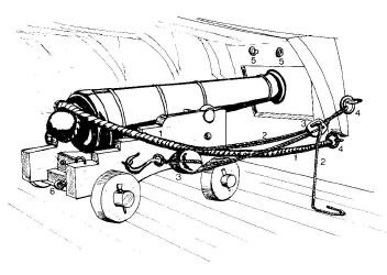
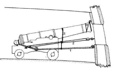
Mark, Do you have a copy of Anatomy of the Ship - The 74 gun Ship Bellona by Conway. Section J contains sketches on the armament. Below are two of the many. I am told there are some inaccuracies but I haven't the knowledge or expertise to say what is what. I will look look in a couple other books I have.
-
Welcome Robert. I've been retired two and a half months, laid off (mutual agreement) seven months prior to that. I am more busy now than ever, chasing all the things that interested me and I hadn't the time before... and finding new interests. I find the days are too short and the nights too long. Back in 1990 I was off due to medical reasons and when well enough ... and thoroughly bored... I turned to model making too. I do know how you feel. My whaler build got me through the worst of it, gave me a focus. You will find no better support group (for modelling) than here... second to the "little boss" of course!
-
De Zeven Provinciën 1665 by Dražen - Scale 1:45
AON replied to Drazen's topic in - Build logs for subjects built 1501 - 1750
simply masterful!- 487 replies
-
- 3
-

-
- ship of the line
- 80 guns
- (and 1 more)
-
Thank you Paul. I had seen that in the photo before posting it and went to have a look. It seems more likely a high angle thing... but having said that I hope I don't find you were correct after all. I guess I'll know for sure soon enough.
-
I have gone down to the dungeon half a dozen times today trying to figure out why the width aligns perfectly with the plan below but the contour of the aft frames don't "flow" naturally into this square frame. Now that you've asked the question the answer to my concern is obvious! I need to check if it should have been tapered. Also, I was reading in TFFM yesterday about the addition of a cross support and was once agained amazed at the authors foresight... or possibly it was a lesson he learned the hard way. I will be removing the frame in a couple minutes. Thank you.
-
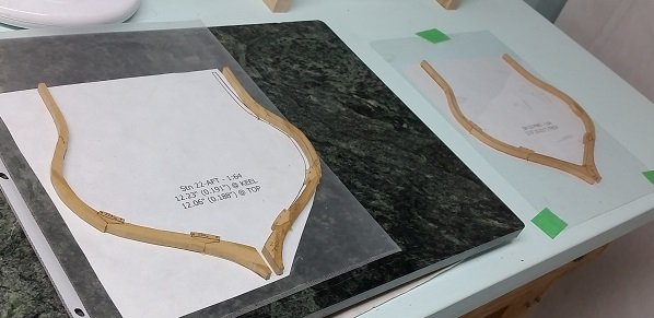
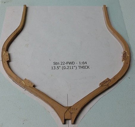
First full square frame installed. #22Fwd. First time I used the square frame support. Clamped the frame to it with an elastic band. Now I start installing the spacer blocks near the top side to lock them all together.

-
Fantastic idea. I have been worried about them popping off prematurely while fairing. I know exactly who to talk to about this.
-
Just removed the support. Glue held! One other view.
-
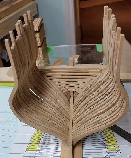
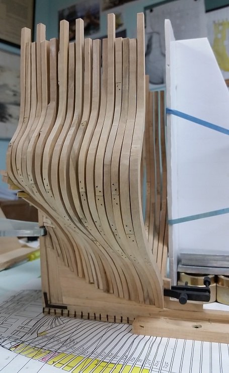
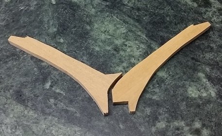
At 6:10 AM today I reached a milestone. I spot glued my last aft cant frame. Her sister (the mirror image frame on the starboard side) gave me all kinds of trouble because of the steep radius on the outside of the lower futtock that mates to the aft deadwood. I had been clamping the frames to the deadwood with a spring clamp (similar to a clothes pin) at this point, but the slope of this one caused the force of the clamp to push the futtock upwards, climbing out of position. I tried a bulldog clip above to stop the migration but it just climbed over that. I then tried other clamps but nothing worked. Finally I used the nose of a mini clamp to simply push the frame against the one behind and this worked. There will be two more frames ahead. They are made up and need some sanding, drilling and installation of the faux bolts through the chocks first. The second last frame is another half frame whereas the last frame to install will be the first full square frame, first to wrap over the keel and not be setting onto the stepping line. It's lower futtock joint was a real treat as a new challenge... I had to do the one half twice to get it correct. Once I have this in place I will install temporary spacer blocks near the top of the frames to stiffen it up for sanding.
-
and there you are! Thank you Greg.
-
Our next meeting is presently scheduled to be on Feb 10th. I will miss this meeting due to a scheduled injection in my eye. The meeting falls in my recovery time. They are discussing rescheduling this meeting (no, not for me) and if so I can ask then, but I feel they (David and Greg?) simply haven't decided as yet. I am sure I will have an opportunity to ask David, but I imagine it takes a bit of effort before they can make a commitment.
-
At this point I am still roughing out. Started by cutting a small block of boxwood (Linden) and marked off the center line, then traced the outline of the image on all four sides. Presently removing down to near proper depths to reveal a block 3D image. Then will come shaping. Likely I will do the heads first, then the arms and wings and work down.... but today I have to glue another frame on my build and then cut more slats, plane to thickness, trace and scroll out yet more frames.... one quadrillion to go!
-
Regarding progress on the figurehead... I am leaving the larger version for the summer but did start the smaller version. The big one is a nice project for the outside patio. The small one is my first stab (spear pun intended) at such a tiny carving. Nothing to brag about as yet. It will likely become kindling and be replaced by a second and third try. I started with my dremel but do not like dealing with the "fur" it creates so I've reverted to my miniture chisels and knives. It is a part time project... forcing myself to walk away and think about the next slice before I screw it up too early in the game. If this one becomes a keeper it will be a fluke. I noticed Admiralty Models is considering having a carving seminar in the future. Not sure if it would be held south or north of the longest ungaurded border... but it got my attention and I am waiting for more news.
-
are we still talking about the stick?
-
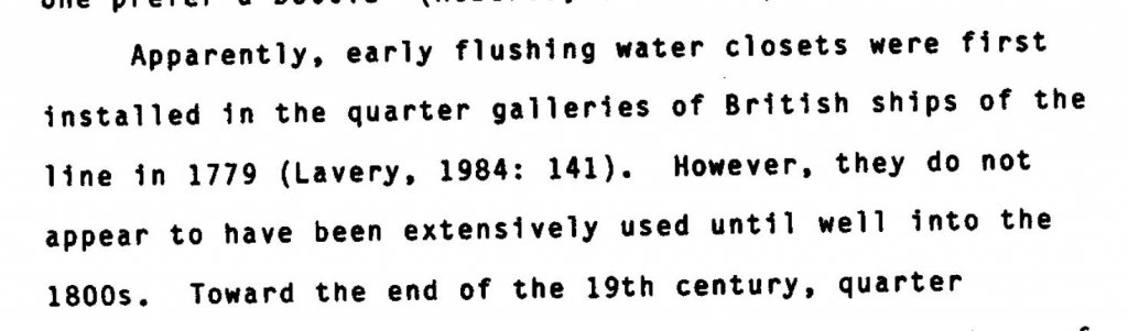
Good morning all. The mention of a "pool" type water collection area over the quarter gallery to provide flush toilets for the officers caught my attention. In my research on "pissdales", there size, shape, locations onboard ships of the line, I found the following... In Joe John Simmons III thesis entitled The Development of External Sanitary Facilities Aboard Ships of the Fifteenth to Nineteenth Centuries for his MA in Anthropology at the Graduate College of Texas A&M University dated Dec 1985 he states the following (see screen capture from thesis below)... As the Bellerophon was completed in 1787, she therefore did have this "pool"! Very interesting.
- 366 replies
-
- 4
-
-
- bellerophon
- victory models
- (and 2 more)
-
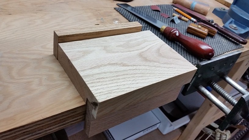
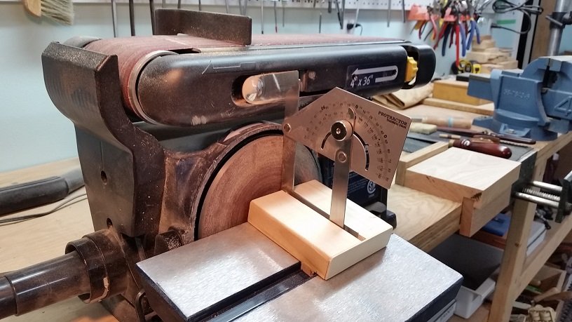
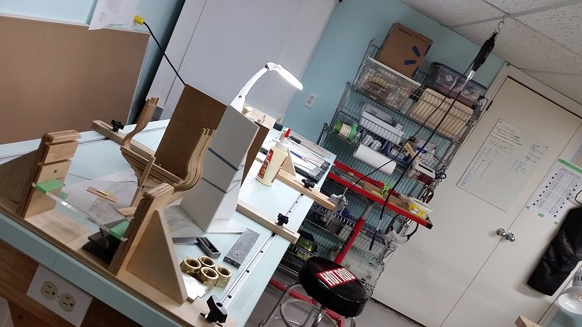
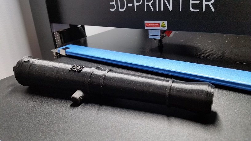
Short update and more. If you're visiting you are probably wonder where had I gone and what have I been up to? Well I am back on my build, have been for weeks. I can proudly say it no longer bothers me to remove frames. It used to tear at my heart and soul. Lord knows how many times I've put them on and taken them off in the last few weeks. I do not give it a second thought anymore. I have gotten frames installed past the location where I last stopped before summer. To recap, I had taken them all off back to the Forward Fashion Pieces, and then I swung my hand over the model and snapped off one of the two forward fashion pieces. It has been remade and installed and it is all now looking good with good alignment. After too many removals and re-installations my CDO (OCD for others) is satisfied. The plan is that I will be putting all frames in (sanding to shape when the aft cant and fore cant frames are installed and then again when those between are in) then marking off the gun ports, then removing frames individually, cutting the gun ports and notches for the cills, and finally replacing them as I go along. It will be a long process as I have many interests and diversions and so do not seem to advance as quickly as other modellers. I will only post when I've something substantial or worthy to look at (or am stumped and need advise) so do not think I've gone for good if you don't see a progress report for awhile. Building and installing frames is repetitive work. Meanwhile I have been lucky enough to have had an opportunity to review all but ten of the 150 issues of the Model Shipwright Magazine (1972 - 2008) and have scanned numerous articles, tips and tricks, etc. that caught my fancy. I will be getting a few more next month. From these I got the idea of a hardwood cutting (sawing/chiselling board). So Yesterday I made one. This inspired me to make a holding setup block for my protractor to free up my hand when setting the adjustable bed on my sander. I had tried numerous methods from clamps to different style protractors but the one in the photo below is my favourite and now I can have one hand on the Allen Key and the other holding the bed. I also attached one photo of my build table as of this morning. Before Christmas I had built a 1:12 scale 9 pound naval cannon (posted on the forum). The cannon and balls were 3D printed for free at the local library. After several attempts they got something I could use but it was in two halves (Breech/Muzzle) and I had to 2 part epoxy glue it together. I found the insignia difficult to see through the Plexiglas case so I had increased the size and finally coloured (painted) it to highlight so it would stand out. I have since purchased a 3D printer and have printed a one piece cannon (1:12) with the insignia at the proper size. One fellow at our club at our meeting earlier this month told me how to clean up the plastic a bit and paint the cannon with an acrylic flat black spray paint. He says the insignia will likely be more noticeable if flat black versus the shiny plastic. So I will be attempting this. Meanwhile I've been trying to print it at 1:64 scale. My first few attempts were a disaster. Today's attempt was better but not quite there yet. Too many adjustments to get it right for the small scale and specific type of PLA plastic... the learning curve. The picture below shows my one piece 1:12 print along with the printer attempting the 1:64 in the background. I apologise for the long story but you may not see another post for awhile.
-
She's white up here also. Guess your getting our left overs! 😂 Edit😆 My mistake is coming from the southwest We (Niagara Region in southern Ontario Canada) are getting your (USA) left overs 😥
-
Good afternoon Mark, As per your request in our earlier PM's I am posting the info here regarding another method to create a scale insignia, or more properly... "Relief sculpting methods for model details". We had our local club meeting on Sunday and I've just updated our website with blogs and photos from that meeting. The method used to sculpt small details was with Weldbond Adhesive. He applies it with the pointy end of a tooth pick and says he has about 5 minutes time before the supply source (he had deposited on a card that he picks off of) sets up. Then he simply squirts some more onto the card and takes droplets from it with his tooth pick and touches it to his model to shape and build up his insignia. It is white (like white glue) when wet and cures transparent. He says it can be scraped and sanded after cured and if it is still not quite right it can be added to afterwards. It works best on porous material (wood) but he is presently using it on copper tubing successfully. He has examples of actual royal insignia on cannons but they are stored away in his son's garage and to use his words, it was too darned cold out there so he gave up looking! For anyone that wants to try this, he suggests you play around with it a bit to get a feel for it and the setup time before you use it on your model. He will be giving a demonstration at our April 14th meeting. For anyone interested in seeing a small sample of his sculpting a photo is posted on our club website: https://modelshipwrightsofniagara.weebly.com/ Please go to our BLOG page and scroll down to January 13th.
-
Mark Re making mistakes... I know this feeling well. Walking away always works so long as I remember to come back. Druxey Re Magic tape After googling it I feel a bit dumber than usual. I normally call it Scotch tape or generically call it Transparant tape. I never noticed the packaging claimed it was magic 😉
-
I just stumbled back here. $4000 gets you the full Standard version of SolidWorks (not the Premium) but anything you print will have a watermark on it.
-
He mentioned it at our last meeting and I can only hope he has done one of the two and will bring it to our next meeting on the 13th of this month.
-
These are really tiny! Mark Taylor (post 1021) mentioned where you can buy them that small. One of the fellows in our local club is sculpting his monogram on his barrel with liquid metal, dental picks and files. I'm not sure if this is an option but thought I'd throw it out there
