KrisWood Posted May 2, 2020 Author Share #121 Posted May 2, 2020 Thank you, Mark, that is great advice! I'll have to get my hands on some carbon paper. I actually did end up doing something very similar to that to fix this, using an X-acto blade to shave off the rounded face made by my filing until it would line up flat against the other side of the joint, one infinitesimally thin shaving at a time. Of course just because it fit together flat in my hand didn't mean it lined up with the plans and when I glued it together again while lined up with the plans it fit perfectly at the top with a tiny gap at the bottom, as if opened like a book. Still, the glue seems to have dried as hard as the wood, and once I sand it down it'll be near imperceptible, so I've decided it's good enough for this attempt. My keel and stems are now assembled straight as an arrow, and I'm moving on. I'll do better on future joints. Quote Link to comment Share on other sites More sharing options...
KrisWood Posted May 2, 2020 Author Share #122 Posted May 2, 2020 Right after my last comment, I noticed I'd messed up on another joint, too. I decided to take it apart and try it your way. I may not have carbon paper handy, but I've got soft lead pencils. I rubbed the flat edge of the lead on the face of one side of the joint, then pressed the two sides of the joint together, quickly staining the highest portions of each face dark. Then it was a simple matter of shaving of the dark spots until each face was perfectly flat and aligned with the other side. It worked! I'm waiting for the glue to dry now. I'm hopeful that this method will come out better than my last attempts. Thanks again! Cathead and mtaylor 2 Quote Link to comment Share on other sites More sharing options...
KrisWood Posted May 6, 2020 Author Share #123 Posted May 6, 2020 So I've got my keel assembled and I've cut out half of the paper templates for my planking bulkheads and I'm looking toward next steps. I've bolded the actual questions in case anyone doesn't want to read this whole wall of text. First, because it was easier to glue the keel and stem parts together when all the pieces were the same width, I made all the parts out of 3/8" solid basswood. Now I need to trim this down to the correct width for each section, as it narrows toward the stems and is widest amidships. I think I can handle this part mostly with a mini-plane and files. What I don't know how to do is the T shaped "wings" on the sides of the keel. Here is what it looks like on a real life boat: https://www.vikingeskibsmuseet.dk/en/professions/education/all-about-the-viking-ship/the-hull-of-the-ship/keel-and-stem That link explains that the T wings are shaped with broadaxe and chisel. How would this be done in miniature? Has anyone here made this kind of keel before? Can you give me any tips as to how I'd go about it? Second, I need to come up with a planking jig to hold my bulkheads. Can anyone give me any tips for aligning them correctly and getting them to stand at the correct height? Here's an example jig I found for another Oseberg model build, but I have no idea how to construct such a thing: https://www.arbeitskreis-historischer-schiffbau.de/mitglieder/modelle/oseberg/ I think nailing something that small into perfect right angles at exactly right spot might be beyond me. >.< mtaylor 1 Quote Link to comment Share on other sites More sharing options...
KrisWood Posted May 6, 2020 Author Share #124 Posted May 6, 2020 One more quick question while I'm on the topic of the keel: How would you make 1:25 scale rivets? The Vikings used square headed nails on one side, with the other side flattened over a square plate. I don't have either of those things nor any idea how I'd flatten the other end. mtaylor 1 Quote Link to comment Share on other sites More sharing options...
Cathead Posted May 6, 2020 Share #125 Posted May 6, 2020 First question: for the straight portion of the keel, you could try carefully running it along a table saw set to just the right depth, then rotating 90 degrees and doing it again. You'd then finish with hand tools. If that's not possible, I'd say use a very sharp knife and a straightedge to progressively carve the notch ouf of the keel. For example, if you need to remove 1/8" of material, use the knife to scribe 1/32" down, then remove material (using that cut as a guide) with the same knife or a chisel. Repeat until the desired depth is reached. For the curved portions, maybe make a template for the curve you need to cut, and use that to guide the knife as you scribe. The easier approach would certainly be to laminate the right keel shape out of multiple pieces, but I think you already rejected that. Second question: You might be best off mounting the keel upright on a build board, then installing the bulkheads. This way you can use metal squares to hold each bulkhead in true (aligned with the board and the keel) while the glue dries. No need for fancy framing. Once they're all in, you'll have an easier time figuring out the right jig for flipping it over and planking. Many of the bulkheads should follow a flat, continous surface in the middle of the ship, so it shouldn't be hard to set up once you've got them attached to the keel. As for nailing together any such jig, just use glue instead. Lets you adjust it until you're happy, then holds well once you leave it alone. If this doesn't make sense, say so and I'll try to make drawings of what I mean. Larry Cowden and mtaylor 2 Quote Eric Current builds: scratchbuilt Missouri River steamboat Peerless (1893); 1:1 scale timber-framed outdoor kitchen Nautical builds (kits): USS Cairo; NRG capstan project; NRG half-hull; Viking longship; US revenue cutter; 18th century longboat; Bounty launch Missouri River craft (scratchbuilt): 1853 Missouri River steamboat Arabia; 1865 steamboat Bertrand; Lewis & Clark barge; keelboat; 1876 steamboat Far West Link to comment Share on other sites More sharing options...
Cathead Posted May 6, 2020 Share #126 Posted May 6, 2020 Third question: Model railroad suppliers often have a lot of detail parts for scratchbuilders. I've seen tiny rivet castings even at 1:87 and maybe they exist at larger scales like 1:48. So if you can find a size that's close, buy a ton. Cheaper version, get a square rod of styrene or brass, blacken it, then cut off thin slices that will look like square nailheads or rivet plates. If you want to try to mimic hammered-over nails, model railroad rail spikes might actually work, as these have an L-shaped head that could look right once they're inserted into a plank. Larry Cowden and mtaylor 2 Quote Eric Current builds: scratchbuilt Missouri River steamboat Peerless (1893); 1:1 scale timber-framed outdoor kitchen Nautical builds (kits): USS Cairo; NRG capstan project; NRG half-hull; Viking longship; US revenue cutter; 18th century longboat; Bounty launch Missouri River craft (scratchbuilt): 1853 Missouri River steamboat Arabia; 1865 steamboat Bertrand; Lewis & Clark barge; keelboat; 1876 steamboat Far West Link to comment Share on other sites More sharing options...
KrisWood Posted May 6, 2020 Author Share #127 Posted May 6, 2020 Hi @Cathead, I don't have a table saw, so that's out of the question. I'll be working entirely with hand tools here. I do have a Dremel that could probably do the same task, but no way to mount it without making a mount from scratch, and no way to buy such a thing during quarantine. I'd rather not glue the bulkheads to the keel as I'd just have to remove them again, and then I'd probably damage the wood / leave glue behind in the process. I do have some heavy gauge copper wire from my metal-smithing classes back in college. I wonder if a cigarette lighter gets hot enough to anneal it and make my own rivets hmmm... mtaylor and Larry Cowden 2 Quote Link to comment Share on other sites More sharing options...
Cathead Posted May 6, 2020 Share #128 Posted May 6, 2020 OK, I may have misunderstood your intentions. Are you planning to build the hull the "authentic" way, with the planks joined to one another as a hollow shell and only adding any frames afterward? In that case, I assume you meant "bulkheads" to refer to whatever formers you're laying the planks over (but not gluing them to), is that correct? I may have been mistaken in assuming you meant "bulkheads" as the internal frames that support the planking in the final vessel, as installing those first is the easier (if less authentic) way to get the same result. If that's the case, assuming you're referring to this photo from your link above, the spacing and shape of the bulkheads would come from your plans. A good set of plans ought to have a series of cross-sections drawn at various defined points along the keel that you can use as templates for the shape of the hull. Actually assembling such a framework would be easy using glue (doesn't have to be nailed) as it isn't part of the model. You could also try carving a solid hull model out of something soft like balsa, again based on your plans, and using that as a base to form the hull planking around. That would have less assembly fuss, though it would take longer to be sure you got the shape you wanted. Making such a solid hull model (usually a half hull) was a very common way for shipwrights to plan out a full-scale vessel during the age of sail, though as far as I know that practice wasn't used by Viking shipwrights. Larry Cowden, KrisWood and mtaylor 3 Quote Eric Current builds: scratchbuilt Missouri River steamboat Peerless (1893); 1:1 scale timber-framed outdoor kitchen Nautical builds (kits): USS Cairo; NRG capstan project; NRG half-hull; Viking longship; US revenue cutter; 18th century longboat; Bounty launch Missouri River craft (scratchbuilt): 1853 Missouri River steamboat Arabia; 1865 steamboat Bertrand; Lewis & Clark barge; keelboat; 1876 steamboat Far West Link to comment Share on other sites More sharing options...
KrisWood Posted May 6, 2020 Author Share #129 Posted May 6, 2020 @Cathead, Yes I'm planning on building it "hull first" rather than "frame first". The best I can think to do would be to glue strips of wood onto a base board, with spaces between to fit the bulkheads into. The bulkheads are drawn from the cross sections in my plans, which the author confirmed for me are drawn to the inside of the planks, so they're perfect for this task assuming I can figure out how to cut them out of plywood without crossing the lines. I think based on that photo and your suggestions I can figure out something for the jig. I also have an idea plan now for how to make rivets by hand. That just leaves figuring out how to carve the T shaped "wings" of the keel with hand tools. mtaylor 1 Quote Link to comment Share on other sites More sharing options...
Cathead Posted May 6, 2020 Share #130 Posted May 6, 2020 Yes, that's exactly right. Mark your baseboard carefully from the plans and erect the bulkheads. I'd suggest glueing one support strip, then the bulkhead, then the other support strip (rather than both first and inserting the bulkhead afterward). That will ensure the tightest fit. I'd also include some blocks between each bulkhead to ensure they're solid and can't bend or move. As for cutting the bulkheads, cut them slightly outside the lines and sand them down. Test out my initial suggestion for the "wings"; scoring and chiseling should get you there with care. Just try it on a scrap piece first to get the hang of it and figure out what method works best for you. Larry Cowden, KrisWood and mtaylor 3 Quote Eric Current builds: scratchbuilt Missouri River steamboat Peerless (1893); 1:1 scale timber-framed outdoor kitchen Nautical builds (kits): USS Cairo; NRG capstan project; NRG half-hull; Viking longship; US revenue cutter; 18th century longboat; Bounty launch Missouri River craft (scratchbuilt): 1853 Missouri River steamboat Arabia; 1865 steamboat Bertrand; Lewis & Clark barge; keelboat; 1876 steamboat Far West Link to comment Share on other sites More sharing options...
KrisWood Posted May 7, 2020 Author Share #131 Posted May 7, 2020 @Cathead, Your suggestion was perfect! I tried it on some scrap wood (a previously failed attempt at making keel parts) and it turned out to be a process very similar to cutting the rabbet in the non-wing part of the keel, just a bit more labor intensive as there is more wood to remove. I think I've got it from here. Thank you! Cathead and mtaylor 2 Quote Link to comment Share on other sites More sharing options...
Cathead Posted May 7, 2020 Share #132 Posted May 7, 2020 Cool. I was actually planning to try a demonstration tonight with a few photos, but sounds like you've figured it out. Looking forward to seeing the result. KrisWood and mtaylor 2 Quote Eric Current builds: scratchbuilt Missouri River steamboat Peerless (1893); 1:1 scale timber-framed outdoor kitchen Nautical builds (kits): USS Cairo; NRG capstan project; NRG half-hull; Viking longship; US revenue cutter; 18th century longboat; Bounty launch Missouri River craft (scratchbuilt): 1853 Missouri River steamboat Arabia; 1865 steamboat Bertrand; Lewis & Clark barge; keelboat; 1876 steamboat Far West Link to comment Share on other sites More sharing options...
KrisWood Posted May 7, 2020 Author Share #133 Posted May 7, 2020 (edited) @Cathead, If you want to give it a try and share any tips you come up with, I'd greatly appreciate that! I'm very new to this so any images I can get are worth a thousand words! Here is the best publicly available reference for how the keel is formed. http://www.unimus.no/felles/bilder/web_hent_bilde.php?id=12384245&type=jpeg There are better plans in the Saga Oseberg book, but they're copyrighted so I don't think I can share them here. Edit: The two things I'm unsure of, and will have to go through some trial and error on: Shaping the wood in a way that doesn't absolutely mangle it to bits (I know the answer to this is to shave smaller bits off at a time with the chisel) How to use the cross sections from the plan of the keel to determine the final shape of the wood. I'm thinking I'll cut out templates for each keel cross section (there is one for each station line in the plans in the book), but that won't get me a smooth curve between the stations. Edited May 7, 2020 by KrisWood Cathead 1 Quote Link to comment Share on other sites More sharing options...
KrisWood Posted May 8, 2020 Author Share #134 Posted May 8, 2020 I started cutting the rabbets last night and drew half of my keel cross section templates at scale for printing. It's good to be finally working with the wood again. Edwardkenway, mtaylor, Cathead and 1 other 4 Quote Link to comment Share on other sites More sharing options...
KrisWood Posted May 9, 2020 Author Share #135 Posted May 9, 2020 (edited) Next step will be the "wings" of the keel. Since I drew these templates myself based entirely on the calculated coordinates of each point at scale, and they look nothing like the plans from the book when drawn this way, I figure they're not copyrighted, so I'll share them here. I've glued the whole sheet of templates to heavy mat board and will shave the keel a little at a time until each station fits. The templates labelled E are for the portions of the keel and stems fore and aft of the stations. Templates 4A through 2F are identical so that's why the sheet is arranged the way it is. Edited May 9, 2020 by KrisWood Cathead and Larry Cowden 2 Quote Link to comment Share on other sites More sharing options...
Cathead Posted May 9, 2020 Share #136 Posted May 9, 2020 Looks like a good plan. KrisWood 1 Quote Eric Current builds: scratchbuilt Missouri River steamboat Peerless (1893); 1:1 scale timber-framed outdoor kitchen Nautical builds (kits): USS Cairo; NRG capstan project; NRG half-hull; Viking longship; US revenue cutter; 18th century longboat; Bounty launch Missouri River craft (scratchbuilt): 1853 Missouri River steamboat Arabia; 1865 steamboat Bertrand; Lewis & Clark barge; keelboat; 1876 steamboat Far West Link to comment Share on other sites More sharing options...
bolin Posted May 9, 2020 Share #137 Posted May 9, 2020 I am planning a similar build as your in the future and am following your progress with interest. Regarding the "plug" to build the hull on I have some ideas. A few months ago I started a course in model boat building and we are building models of Swedish clinker built small vessels. They are rather similar in concept to a viking age ship, so the construction method should be feasible. I haven't come very far with my model since to the course have a break due to corona. Here are some pictures. Note that my model is only a small dory, which does not have a keel nor a stem or stern post. It only has a bottom plank and flat transoms in the fore and aft. However, the same construction principles should be possible to use for larger ships and with keels. That is at least what I plan to do when I get to my build. The reason that the "frames" are angled is so that they align with the real frames of the original. If I remember correctly the Oseberg ship has angled frames in the for and aft? A comment on a rivets. They may not necessarily be visible at scale. The following picture is how a hull side looks after 35 years of tar and use. Cheers Larry Cowden, GrandpaPhil, KrisWood and 1 other 4 Quote Current builds Meta - Billing Boats - Pentikontoros - Navarino Completed builds Swampscott Dory - BlueJacket - Will Everard - Billing Boats - Bohuseka (Swedish west-coast rowboat) - scratch build - Medieval long-ship Helga Holm - scratch build - Sloop from Roslagen - scratch build Link to comment Share on other sites More sharing options...
KrisWood Posted May 9, 2020 Author Share #138 Posted May 9, 2020 @bolin, that's an awesome build you've got started there! I find it curious that your frames seem to put the garboard strake inside of the second strake. Is this intentional? I had no idea that dories were built this way! Do you have a build log on Model Ship World that I could follow? The heads seen along the edges of the planks in that photo of a boat after years of use are actually nails, not rivets, and may very well not be visible at scale. There are what look to be larger rivet heads along the frames further down, and those would be visible on my Oseberg model at 1:25 scale. I'll have to do some math to figure out the exact measurements for my nails, trenails, and rivets once I get to the point where I'm planking this thing. At the very least I want to include the rivets and trenails that hold the scarfs of the keel and stem sections together, but I can't do those until the final shaping of the keel and stems is done. Yes, the frames of the real life Oseberg are angled. I'm not sure yet how I'll handle this in my model. I have very little reference for the shape of the frames. All of the drawings I have are from the front view as drawn by Johannessen (the conservator of the ship that put it together in the museum), and Lundin (who drew plans based on the museum display of the ship. The only plans I know of that show the frames in their actual dimensions as if laid flat on the ground were drawn by Glende, an engineer who drew all the parts of the ship in situ as they were excavated. Unfortunately, though multiple sources reference Glende's sketchbook, I have been unable to find a copy of this anywhere. I only have a handful of drawings from it that are publicly available through the photo portal on the http://unimus.no/ website. http://www.unimus.no/felles/bilder/web_hent_bilde.php?id=12417098&type=jpeg It doesn't help that all the websites that have information about it are in Scandinavian languages that I do not speak. >.< Larry Cowden and mtaylor 2 Quote Link to comment Share on other sites More sharing options...
KrisWood Posted May 9, 2020 Author Share #139 Posted May 9, 2020 Actually, while looking at the unimos website just now I did find one drawing of the some of the frames by Glende, that appear to be from the excavation, but I'm uncertain if these are drawn "flat" or if they are drawn as viewed at an angle from the front. I think I can use them, though, to determine the structure of the frames if not the actual dimensions, and then get the dimensions from my planking bulheads but with the planks trimmed off. http://www.unimus.no/felles/bilder/web_hent_bilde.php?id=12384236&type=jpeg Larry Cowden and mtaylor 2 Quote Link to comment Share on other sites More sharing options...
bolin Posted May 9, 2020 Share #140 Posted May 9, 2020 I have not started a build log for the dory yet as the progress got interrupted when the course where I build it was paused due to corona. I will start a log when or if I restart the build. Yes the garboard strake is very oddly placed on this boat, but the plans are from an actual boat in a museum, so it’s authentic. I don’t know if this was an oddity by just this boatbuilder, or if it was a more common pattern. Most of the rivets in the picture is real rivets. The ones closest to the camera are nails that holds the plank to the stern. The bigger heads seen along the hull are treenails for holding the frames to the hull. I guess those can be modeled using a toothpick or similar. Cheers mtaylor and KrisWood 2 Quote Current builds Meta - Billing Boats - Pentikontoros - Navarino Completed builds Swampscott Dory - BlueJacket - Will Everard - Billing Boats - Bohuseka (Swedish west-coast rowboat) - scratch build - Medieval long-ship Helga Holm - scratch build - Sloop from Roslagen - scratch build Link to comment Share on other sites More sharing options...
bolin Posted May 9, 2020 Share #141 Posted May 9, 2020 The text on the drawing says “snit” which means cut along the lines A-B etc in the line drawing to the left. I.e. the frames are essentially drawn flat. Cheers KrisWood and mtaylor 2 Quote Current builds Meta - Billing Boats - Pentikontoros - Navarino Completed builds Swampscott Dory - BlueJacket - Will Everard - Billing Boats - Bohuseka (Swedish west-coast rowboat) - scratch build - Medieval long-ship Helga Holm - scratch build - Sloop from Roslagen - scratch build Link to comment Share on other sites More sharing options...
KrisWood Posted May 9, 2020 Author Share #142 Posted May 9, 2020 @bolin, thank you for the translation, you are my hero today! There are more detailed drawings by the conservator, Johannessen. I'll check them for the word "snit" also. I should have guessed that myself, as I speak a little german, which has a very similar word "schnitt" for "cut", but I didn't know that that would mean "drawn flat" in this context. This will be very helpful information once I start making the frames! mtaylor 1 Quote Link to comment Share on other sites More sharing options...
bolin Posted May 10, 2020 Share #143 Posted May 10, 2020 In this case "snit" does not actually mean "lay flat", but it points out the cuts in the drawing. The cut L-M is indicated on the drawing (see the letters above and below). And the corresponding frame The text below says "cut L-M seen from the fore". Cheers KrisWood, GrandpaPhil, Larry Cowden and 1 other 4 Quote Current builds Meta - Billing Boats - Pentikontoros - Navarino Completed builds Swampscott Dory - BlueJacket - Will Everard - Billing Boats - Bohuseka (Swedish west-coast rowboat) - scratch build - Medieval long-ship Helga Holm - scratch build - Sloop from Roslagen - scratch build Link to comment Share on other sites More sharing options...
KrisWood Posted May 10, 2020 Author Share #144 Posted May 10, 2020 That’s awesome! So it basically means cross section? Quote Link to comment Share on other sites More sharing options...
bolin Posted May 11, 2020 Share #145 Posted May 11, 2020 Yes, snit (or snitt in Swedish) can mean cross section as well. KrisWood and mtaylor 2 Quote Current builds Meta - Billing Boats - Pentikontoros - Navarino Completed builds Swampscott Dory - BlueJacket - Will Everard - Billing Boats - Bohuseka (Swedish west-coast rowboat) - scratch build - Medieval long-ship Helga Holm - scratch build - Sloop from Roslagen - scratch build Link to comment Share on other sites More sharing options...
malachy Posted May 11, 2020 Share #146 Posted May 11, 2020 Ha. KrisWood, that's a name I haven´t seen in a long time (PotBS and PA! forums?). Looking forward to your build, the Oseberg ship certainly is an interesting subject mtaylor 1 Quote Link to comment Share on other sites More sharing options...
KrisWood Posted May 11, 2020 Author Share #147 Posted May 11, 2020 Hi Malachy! Yup, that's me, though I never did PA other than maybe I asked a few 3D modeling boat questions in the forums. It's been so long that I can't remember. 😆 How've you been? mtaylor 1 Quote Link to comment Share on other sites More sharing options...
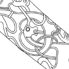
bigpetr Posted May 12, 2020 Share #148 Posted May 12, 2020 Hi KrisWood, I am folowing your build with great interest. Some thoughts on rivets. I do not know the measurements of rivets at Oseberg ship, but on Gokstad ship, I am building right now, rivet head diameter is 2,5cm. It means 1mm in 1:25 scale, so I think they will be noticeable and will look great on the model in 1:25 scale. Here is rivet test I did on my Gokstad model 1:48 scale. Rivet has 0,5mm in diameter. After this test I decided I will make them. Eventhou they will be covered by "tar" colour their presence will be noticeable. It will be lots of work to add them but it will be worth it. KrisWood, Larry Cowden, mtaylor and 1 other 4 Quote Link to comment Share on other sites More sharing options...
KrisWood Posted May 12, 2020 Author Share #149 Posted May 12, 2020 Hi @bigpetr! That's a nice looking rivet head. How did you make it? mtaylor 1 Quote Link to comment Share on other sites More sharing options...
bigpetr Posted May 13, 2020 Share #150 Posted May 13, 2020 Rivet head is punched from 0,1 mm thick paper by this jewelery tool. I also use it to punch holes to paper. mtaylor and KrisWood 2 Quote Link to comment Share on other sites More sharing options...

Recommended Posts
Join the conversation
You can post now and register later. If you have an account, sign in now to post with your account.