CDR_Ret
-
Posts
548 -
Joined
-
Last visited


.thumb.jpg.a354db03134920ba16c2c840f8430fbb.jpg)


-
 robert952 reacted to a post in a topic:
Text - image - text - image
robert952 reacted to a post in a topic:
Text - image - text - image
-
CDR_Ret reacted to a post in a topic:
Text - image - text - image
-
mtaylor reacted to a post in a topic:
Text - image - text - image
-
Ryland Craze reacted to a post in a topic:
Text - image - text - image
-
 PvG Aussie reacted to a post in a topic:
Text - image - text - image
PvG Aussie reacted to a post in a topic:
Text - image - text - image
-
CDR_Ret reacted to a post in a topic:
Text - image - text - image
-
Scottish Guy reacted to a post in a topic:
Text - image - text - image
-

Text - image - text - image
CDR_Ret replied to PvG Aussie's topic in How to use the MSW forum - **NO MODELING CONTENT**
I usually type in the text for a post in its entirety and leave a space (Return) between paragraphs. Then I upload the images I want to include in the post. This is a separate and preliminary action to actually inserting the image. Their thumbnails appear in a row in the UPLOADED IMAGES section below the text window. Next, you place the cursor at the location to insert the image within the text (usually at one of the blank lines). And finally, hover your cursor over the image you want to insert, then click on the "Insert" button that appears. That action inserts the image into the post. The default alignment is left-aligned. You can center the image by ensuring your cursor is adjacent to the image and then left-clicking the center alignment icon in the formatting row at the top of the post. You can also resize the image after it is inserted by double-clicking it. You can only make it smaller than its original size. And make sure the "Keep original aspect ratio" checkbox is checked, otherwise your image will be distorted if you change the width. Terry -
CDR_Ret reacted to a post in a topic:
Free CAD program
-
Roger Pellett reacted to a post in a topic:
Free CAD program
-
 CDR_Ret reacted to a post in a topic:
Free CAD program
CDR_Ret reacted to a post in a topic:
Free CAD program
-
NavyShooter reacted to a post in a topic:
Free CAD program
-
gsdpic reacted to a post in a topic:
Free CAD program
-
Scottish Guy reacted to a post in a topic:
Free CAD program
-
Free CAD program
CDR_Ret replied to Frank Burroughs's topic in CAD and 3D Modelling/Drafting Plans with Software
Hello Frank. After working with various 3D CAD programs for nearly two decades, I think that you should first decide what the ultimate purpose and scope of using this approach will be for your projects. Are you primarily intending to reconstruct and fair existing plans? Is your intent to 3D print the entire hull structure and superstructure? Or are you mainly interested in printing the smaller parts and otherwise creating the ship's structure out of conventional materials? For validating and fairing existing ship's plans, especially those from the 19th century and earlier, I recommend the DELFTship Free software. It is a for-the-purpose naval architectural program that defaults to three standard views, provides infinitely customizable stations, waterlines, buttocks, and diagonals, and has reasonably easy-to-use modeling tools such as Gaussian and developable visualization of hull surfaces. All these features are built-in and appropriate for ship design and modeling. This is the go-to program for developing smooth, fair hull surfaces. The poor documentation for the hobbyist and nautical research modeler is its main drawback, in my opinion. Search this forum using the term "DELFTship" to take a look at some of the results by several modelers/researchers (myself included) using this program. For 3D printing large components such as the hull, deck cabins, boats, etc., you may want to check out some of the software mentioned above. I have no experience with that application. For small details and relative ease of modeling, I would go with the free, open-source, full-feature Blender program. However this program has a notoriously steep learning curve. Take a look at the Blender tutorial series by BornCG on YouTube if you want to consider this route. The instructor is an excellent teacher who doesn't assume you know what the buttons do and how the multitude of program features work. Sadly, most of the competent 3D programs do have that steep learning curve, so plan on spending some time figuring out ship design within the program you choose. Some of the standard 3D CAD programs are pretty clunky when attempting to create a continuously varying surface in 3-space that must conform to an existing set of plans. I can assist with DELFTship. @3DShipWright and @Martes may provide assistance with Blender. Take a look at their models, which are both accurate and very aesthetic. They are going more for illustrative results than 3D printing. Terry -
CDR_Ret reacted to a post in a topic:
PHOENIX 1787 by ccoyle - Master Korabel - 1/72 - Russian brigantine of the Black Sea Fleet
-
CDR_Ret reacted to a post in a topic:
Hello from Iowa
-
mtaylor reacted to a post in a topic:
Hello from Kiowa, Colorado
-
Hello Doug from Colorado Springs! Welcome aboard. Terry
-
CDR_Ret reacted to a post in a topic:
Hello from Kiowa, Colorado
-
CDR_Ret reacted to a post in a topic:
Hello from Kiowa, Colorado
-
Ship Ribbing with CAD?
CDR_Ret replied to Sanjith_D's topic in CAD and 3D Modelling/Drafting Plans with Software
I would recommend checking out this thread regarding laser-cut frames, etc. Kiyoo Iizawa was actively involved in this forum a few years ago and did some beautiful work using CG modeling and laser-cut components. He was writing a manual/book to help modelers get into laser-cutting modeling, but after some attempts at collaboration, I think there was an (amicable) divergence of views on how to present the process. Terry -
Ship Ribbing with CAD?
CDR_Ret replied to Sanjith_D's topic in CAD and 3D Modelling/Drafting Plans with Software
IMHO, going directly from existing drawings to code that drives a 2D laser cutter is risky when cutting out frames or bulkheads. I have no experience with the quality of plans from the big national museums and other credible sources, but when I manually compared the body and halfbreadth plans of my 1891 brigantine project, it was an exercise in frustration. Heights and breadths of station and waterline intersections did not agree among the three views. The point I am trying to make is that there is no guarantee that using existing plans (especially if they are old, original drafts) will drive a laser cutter that will result in a smooth, fair, hull surface without a lot of extra work. The above observation was the reason I went to CG drafting in the first place. After nearly a decade of periodic frustration, trying different methods and different copies of plans from the Smithsonian and other museum/library archives, I found that using the DELFTship Free naval architecture software was pretty much ideal for fairing out the hull lines because it had the features needed to visualize the shape of the hull, remove low and high spots, and compare the resulting lines to the original drawings. The bottom line here is that obtaining a set of working plans that will actually be fair and eyepleasing in the real world won't necessarily yield the same set of station lines, waterlines, and buttock lines as in the original set of plans you obtained. It is up to you how far you are willing to deviate from the original drawings. There are a number of MSW members who have posted their projects using DELFTship Free, including my own. Comparison of the final modeled stations (green) in DELFTship Free compared to the original G.C. Berger drawing stations. Waterlines (blue) were included to ensure the correct vertical scale. To understand the genesis of these lines, please refer to the Galilee research log in my signature. (High-resolution plans obtained from the San Francisco Maritime National Historical Park Library; G.C. Berger, Pacific Marine Research Society; Date and provenance unknown.) Once you have what appears to be a valid set of lines to work with, then you can start thinking about what laser setup to use for cutting out your parts. Remember to cut to the outside-most of the front and back curves for each frame or bulkhead. Terry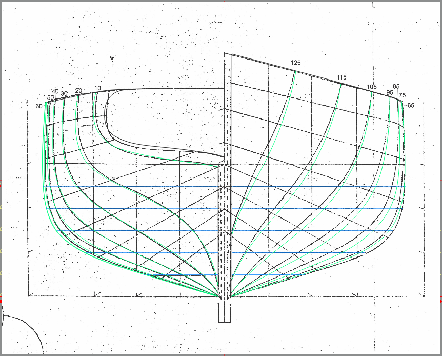
-
USF Confederacy in 3D | Blender
CDR_Ret replied to 3DShipWright's topic in CAD and 3D Modelling/Drafting Plans with Software
Beautiful, Nate! Terry -
3D Ropes/Rigging in Blender
CDR_Ret replied to 3DShipWright's topic in CAD and 3D Modelling/Drafting Plans with Software
So far, so good! -
Welcome aboard, Kevin! Yeah, the Lewis and Clark is nothing but HY-80 razor blades. There are quite a few (mostly former) bubbleheads as members here. Terry
-
Hey, Deyson. Another Coloradoan! Where are you located? I'm retired and living near grandchildren in the Springs. Great to have you aboard! Terry
-
Viriato. Eu sugiro usar o translate.yandex.com tradutor português / inglês. Isso parece fazer um trabalho muito preciso. (I suggest using the translate.yandex.com Portuguese/English translator. That seems to do a really accurate job.) Terry
-
Try reading it via the link on a mobile phone. Worked fine for me. Sad outcome.
-
My laser cut planks
CDR_Ret replied to modeller_masa's topic in Building, Framing, Planking and plating a ships hull and deck
You guys should work up a tutorial for developing laser patterns for things like cabin and roof planking, skylights, and other fine details. You might even start a small business of doing bespoke laser cutting jobs to pay for your hobby! Terry -
3D Brig 'Rose' in Blender 3.3x
CDR_Ret replied to 3DShipWright's topic in CAD and 3D Modelling/Drafting Plans with Software
Is there a simple way to add realistic crew in these renders? The main thing that indicates your image is artificial is the absence of any hands visible on deck, or at least at the wheel. Galilee had only eight assigned crewmembers (plus the five scientific expedition members), and all the photos of the ship at sea always had at least a few humans visible topside. Terry -
Most browsers have a feature to translate text to the user's default language. Looks pretty clear to me. Nice job on Bismark! Terry
-
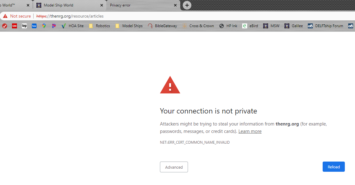
A big miss in only 42 to 48 hours
CDR_Ret replied to DaveBaxt's topic in How to use the MSW forum - **NO MODELING CONTENT**
Not sure who to send this to, but I received this security message when I tried to access the site's article database: Probably not related to this weekend's mishap, but thought you should know. Terry