Moony
-
Posts
82 -
Joined
-
Last visited


-
 Meriadoc Brandybuck reacted to a post in a topic:
Italian Coasting Sailer Lautello by Moony - PoB 1/50
Meriadoc Brandybuck reacted to a post in a topic:
Italian Coasting Sailer Lautello by Moony - PoB 1/50
-
Nirvana reacted to a post in a topic:
Anchor Hoy by Maurys - POF Harbor craft c. 1825 -- 1:48 - Finished
-
Moony reacted to a post in a topic:
SCHOONER ENTERPRIZE by GConiglio - POF
-
Moony reacted to a post in a topic:
Schooner Altair by KeithAug - Scale 1:32 - 1931 - Finished
-
mtaylor reacted to a post in a topic:
Italian Coasting Sailer Lautello by Moony - PoB 1/50
-
Moony reacted to a post in a topic:
1776 English Sloop by NJQUACK – FINISHED - 1:75
-
Moony reacted to a post in a topic:
French Schooners (La Jacinthe Type): La Mutine and La Topaze by Gregor – 1:64 scale, 1823 / 1835
-
 Thanks John, the project gives some interesting possibilitys for exercises to me. At the moment I'm palning th baseboard: Here the rough cutout of the 4mm - plywood baseboard - in some Italian forums thread about a Schiffazzo I found the same measurement for the thickness of plywood used for the same scale). Here the construction of the opening in the base board - and looking for a solution to get rectangular joinings (picture will come after paint will work again): this was the source of my idea: the reason is rectangularity of the soft poplar plywood, a proper surface I could sand and certainly to get more contact area to glue the planks... and I can work with the wood I've already got and don't have to "enlarge my budget" .. any eigth to eight millimeter softwood square sticks will not to be able to buy at common in a DIYshop. What do you think about my trick?
 -
mtaylor reacted to a post in a topic:
Italian Coasting Sailer Lautello by Moony - PoB 1/50
-
grsjax reacted to a post in a topic:
Italian Coasting Sailer Lautello by Moony - PoB 1/50
-
Very nice sideview - but NO scuppers here!
-
mtaylor reacted to a post in a topic:
Italian Coasting Sailer Lautello by Moony - PoB 1/50
-
Omega1234 reacted to a post in a topic:
Italian Coasting Sailer Lautello by Moony - PoB 1/50
-
Omega1234 reacted to a post in a topic:
Italian Coasting Sailer Lautello by Moony - PoB 1/50
-
Here the view on plansides and some details: and at the very ed the proof of scale: not 100&% but close eough to the 1/50 I wanted to have... the paper is working in the copyingmaschine a lot when drying in the haeter to fix the toner.
-
Omega1234 reacted to a post in a topic:
Fram by Tadeusz43 - scale 1:100 polar exploration ship
-
mtaylor reacted to a post in a topic:
Italian Coasting Sailer Lautello by Moony - PoB 1/50
-
Hello friends, as the S/S Warkworth costs a plenty of mindwork I decided to add a second project less complicated and time consuming. So I leafed through the plans I've stored and found some very nice old "chances" but mostly the were to complicated and sophisticated as a "sidecar-building". So I figured out the exercisebook sized Modelarstwo Okretowe Special No. 19 of May 2015: The prototype is a Sicilan/Southitalian Coasting boat of the 1860th with a length between 15 to 20 meters and a 1/3 Length/Breadth ratio. Here a pencil drawing I found several years ago in teh web - I think on an Italian site. Here well to see the line of scuppers on the underside of the bulkwalk. The Lauretto was used for short sea trades and a fasr as my Latin knowledge translates some Italian websides I figured out thet the latin-rigged boats made also journeys to the North African coast. So this little ships were used in transport purposes and fast and handy ships to sail. It looks like the were used in transport of general cargo in sacks, barrels and boxes - no bulk cargos seem to be stored under the hatches. I couldnt find out what are the diffrences and relationsship features to the also latin-rigged Schiffazzo - but there were both: similaritys and diffrences. But let stay us with the Lautello in exspecial the "after castle" that is not found on the threemasted 1 Schiffazzo -here scale to 1/50; As you can see from the MO-issiue's cover the hatches are closely covered - the plan gives us a grating hatchcover all over here. The plans delievered with the MO are allways very good and they have got a fantasic price. I was able to enlarge the hull's drawings up to 1/50 and so I can start with the work very fast - hopefully some more knowledgeable of you may help with further and deeper information to this article. Next stop: taking photos of the enlarged plan. 1 edit
-
Here I foud what Ithought it was lost: ad it looks very well: and lets crosscheck: 304.8mm for a foot brought to scale by deviding with 48 gives 6,35 mm to us... multiplicated with 5 we got 31.75 mm ...but so the job I gave to the guy in the copyshop is now prooved to be devastantingly realised - and I can't change it for a right done one!!! Now I can go there and I'll have to redo this work on my own.
-
Okay We have got a Breadth moulded from 27 feet (page 1 #1) when we multiplicate this with around a food of 304.8mm so we get 8,229.6mm so we start to devide this through our scale ratio of 48 so Sesamstreat's Count will teach us "So we'll get 171.45mm at the very end!" But! So I do't trust myself to sit an a toilretseat i the right way!
-
Moony reacted to a post in a topic:
Cruizer-class Brig-Sloops of the Royal Navy
-
HyTadeusz, That looks great, good progress - can you show us a little bit mot of the how vou gozt from he plans drawing to the bulkheads shap you used at the end? It's important for me due to the open hatches, stairhouses and skylights you can look inside the ship. I'm looking for further progress and sending best wishes from Berlin,
-
Moony reacted to a post in a topic:
Fram by Tadeusz43 - scale 1:100 polar exploration ship
-
Moony reacted to a post in a topic:
Fram by Tadeusz43 - scale 1:100 polar exploration ship
-
Moony reacted to a post in a topic:
Fram by Tadeusz43 - scale 1:100 polar exploration ship
-
Here a contemporary picture of a staemer - point of intrest for me is the canvasing of the flying brigde:
-
Moony reacted to a post in a topic:
Captains Barge c.1760 by Siggi52 - FINISHED - 1:48 - small
-
Moony reacted to a post in a topic:
Captains Barge c.1760 by Siggi52 - FINISHED - 1:48 - small
-
Hello, after several month filled with job, illness, divertissments (i.e. addtivly kitchen furniture manufacturing ) and some of trials of redrawing I can now bring some further news during the next days... I was very happy to find a yard model of S/S Warkworth... also something to do with Newcastel on Tyne and she was a singel screw steamship ,too. Source: vallejogallery.com but it was her a later bearer of the same name... So let's look forward to the awaited progress: new Mr McSale in 1/48 trial of the deck's beam stencil redrawing of the formers Hope you all are well, Yours
-
Hy Maury! That's a fine example of some so often neglected working craft. Perhaps somebody is going to copy it, placing it beside a warship in some diorama to show it at work. Thanks for sharing. I'm looking foreward to your progress.
- 525 replies
-
- 3
-
-
- anchor hoy
- hoy
- (and 1 more)
-
Ian, your argument mad me thinking if the procedure would make sense... as I used to ask: a ) Why should we act in this way? (Is it done in the most secure, effective, fastest & cheapest way?) b ) Why should it be constructed in this way? (Does it fit in the place it is put in - i.e. Does the crane collidate with anything in its pivoting range?) bb ) Could it have been constructed at this time in this way? (Ancorsteamwinch on deck of the Victory!) c ) Does it make sense to work in this way at all? (i.e.: May there have been an ash hatch running comfortablely beside the boiler down through the doublebottom right into the sea not annoying any 1st Class passangers - as they may have used it in boilerroom No.1 on RMS Titanic? ) On the side of the furnanche openings there were no hatches - the only openigs up through the deck are the vents... and nobody (i.e. engeneers!!!)) would like the ash to fall on the oily engine when brought arround the boiler to be lifted up through the skylight of the engine room. What do you think is my idea right?
-
Thanks for your answers & motivation power giving within towards me, guys! But as I told you still in the 20th and 30th it was done like this in older coasters not having added with a special ash hatch to cuck it outboard through the hull's side. I'll figure out the exact page where I read it - it is allways the same, isn't it? You know it, You know you read it, You know the book you read it, ...but on what page or in what story this special factum was told to you? You can't remember...
-
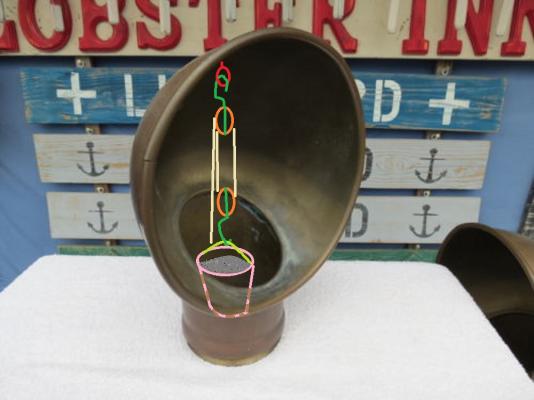
At the moment I read "Old time Steam Coasting" by Spargo & Thomason with a good benefit to several details of the boiler or engine room and to the accomodation in coasters. So I figured out the in the pre 1900 coasters the ash was brought out of the boilerroom by adding it into a bucket . And lifting it to the deck through the vent by a winch. So there must be a hook or eyelet or dee to suspent a set of pulleys in the top of the vent's inlet... So what do you think about my here added my 1st scetch?