Clark
-
Posts
238 -
Joined
-
Last visited
Recent Profile Visitors
1,884 profile views

.jpg.d84ec4dad1d7791e855dca06210ab6f3.thumb.jpg.f45209242e851d4409eca1a09293165b.jpg)


-
 Clark reacted to a post in a topic:
Chris Watton and Vanguard Models news and updates Volume 2
Clark reacted to a post in a topic:
Chris Watton and Vanguard Models news and updates Volume 2
-
Clark reacted to a post in a topic:
HMS Indefatigable 1794 by Blue Ensign - FINISHED - Vanguard Models - 1:64 scale
-
Clark reacted to a post in a topic:
Chris Watton and Vanguard Models news and updates Volume 2
-
Clark reacted to a post in a topic:
Chris Watton and Vanguard Models news and updates Volume 2
-
Clark reacted to a post in a topic:
Sloop Speedwell 1752 by Chuck - Ketch Rigged Sloop - POF - prototype build
-
Clark reacted to a post in a topic:
HMS Portland 1770 by scrubbyj427 - 1:48 - 4th rate 50-gun ship
-
Clark reacted to a post in a topic:
HMS Indefatigable 1794 by Blue Ensign - FINISHED - Vanguard Models - 1:64 scale
-
Clark reacted to a post in a topic:
HMS Sphinx 1775 by aydingocer - Vanguard Models - 1:64 - Revision #2
-
Clark reacted to a post in a topic:
HMS Sphinx 1775 by aydingocer - Vanguard Models - 1:64 - Revision #2
-
Clark reacted to a post in a topic:
HMS Sphinx 1775 by aydingocer - Vanguard Models - 1:64 - Revision #2
-
schooner reacted to a post in a topic:
24 ft Launch by Clark - FINISHED - Vanguard Models - 1:64 scale
-
KARAVOKIRIS reacted to a post in a topic:
24 ft Launch by Clark - FINISHED - Vanguard Models - 1:64 scale
-
KARAVOKIRIS reacted to a post in a topic:
24 ft Launch by Clark - FINISHED - Vanguard Models - 1:64 scale
-
KARAVOKIRIS reacted to a post in a topic:
24 ft Launch by Clark - FINISHED - Vanguard Models - 1:64 scale
-
KARAVOKIRIS reacted to a post in a topic:
24 ft Launch by Clark - FINISHED - Vanguard Models - 1:64 scale
-
Thukydides reacted to a post in a topic:
24 ft Launch by Clark - FINISHED - Vanguard Models - 1:64 scale
-
Blue Ensign reacted to a post in a topic:
24 ft Launch by Clark - FINISHED - Vanguard Models - 1:64 scale
-
bruce d reacted to a post in a topic:
24 ft Launch by Clark - FINISHED - Vanguard Models - 1:64 scale
-
bruce d reacted to a post in a topic:
24 ft Launch by Clark - FINISHED - Vanguard Models - 1:64 scale
-
bruce d reacted to a post in a topic:
24 ft Launch by Clark - FINISHED - Vanguard Models - 1:64 scale
-
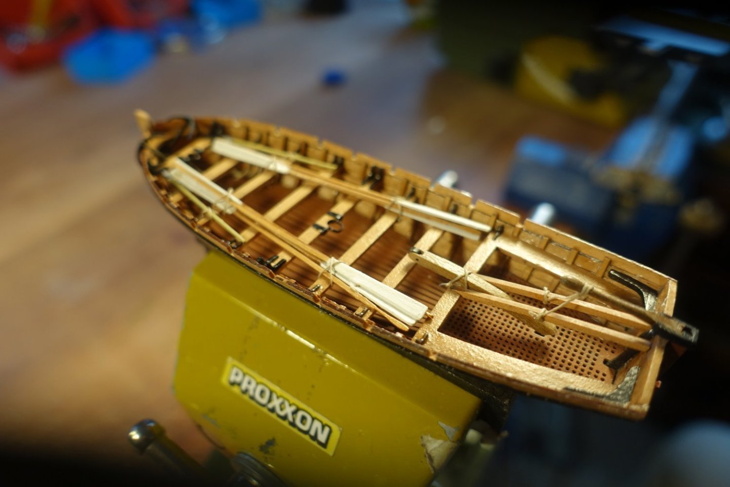
The boat is ready and waiting to be lashed to the Sphinx. I hope that this report will encourage some people to build these nice little boats. After all, they take up very little space,


- 20 replies
-
- 6
-
-
- 24 ft Launch
- Vanguard Models
- (and 1 more)
-
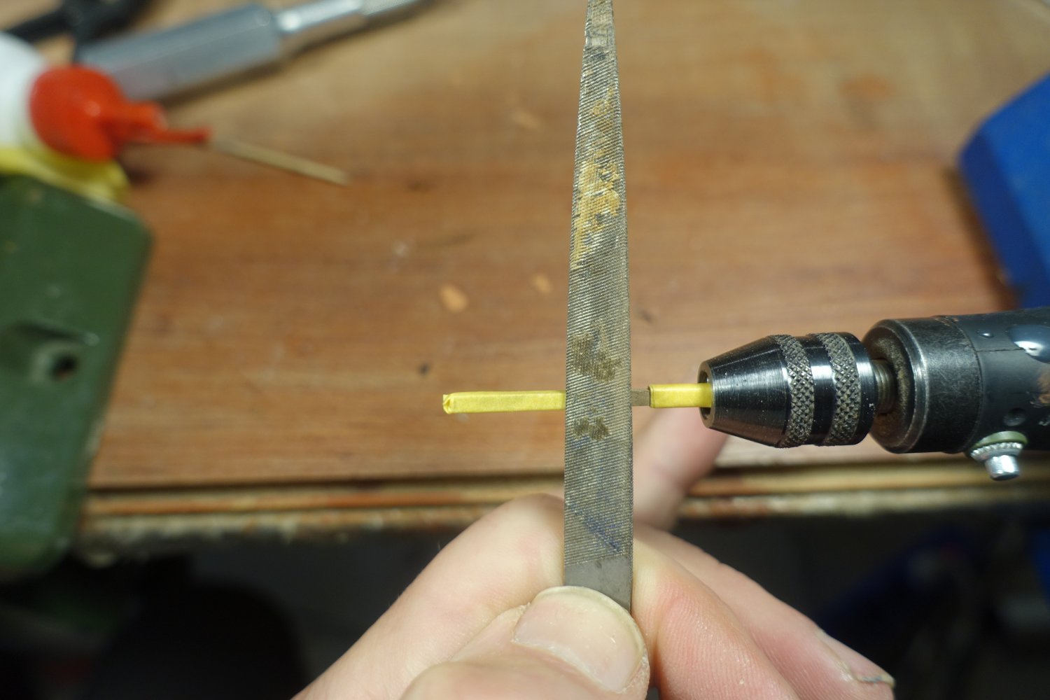
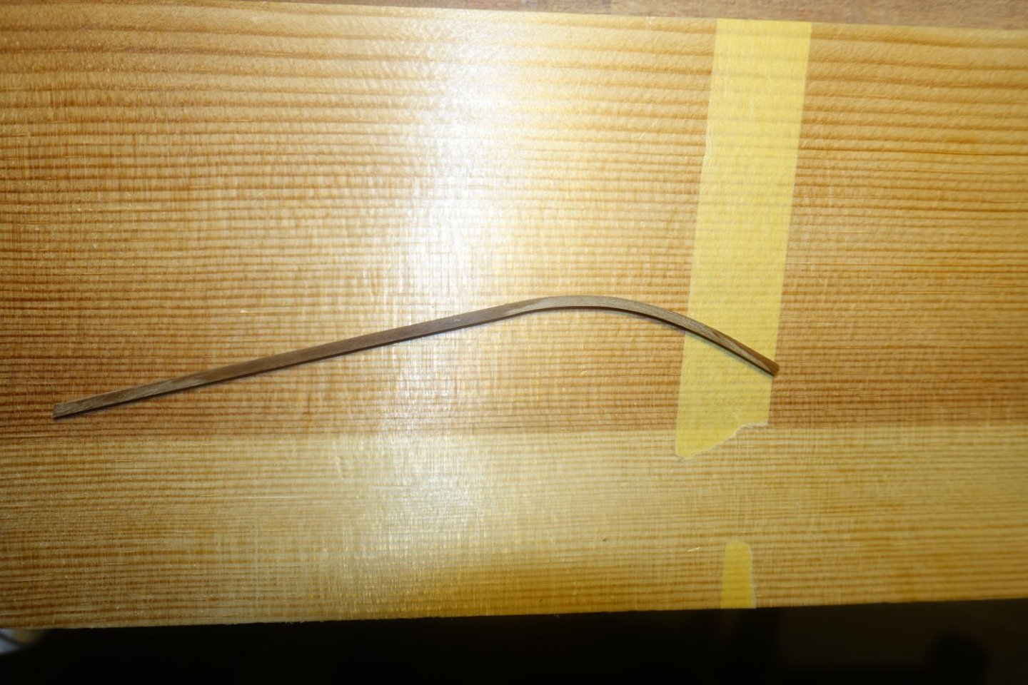
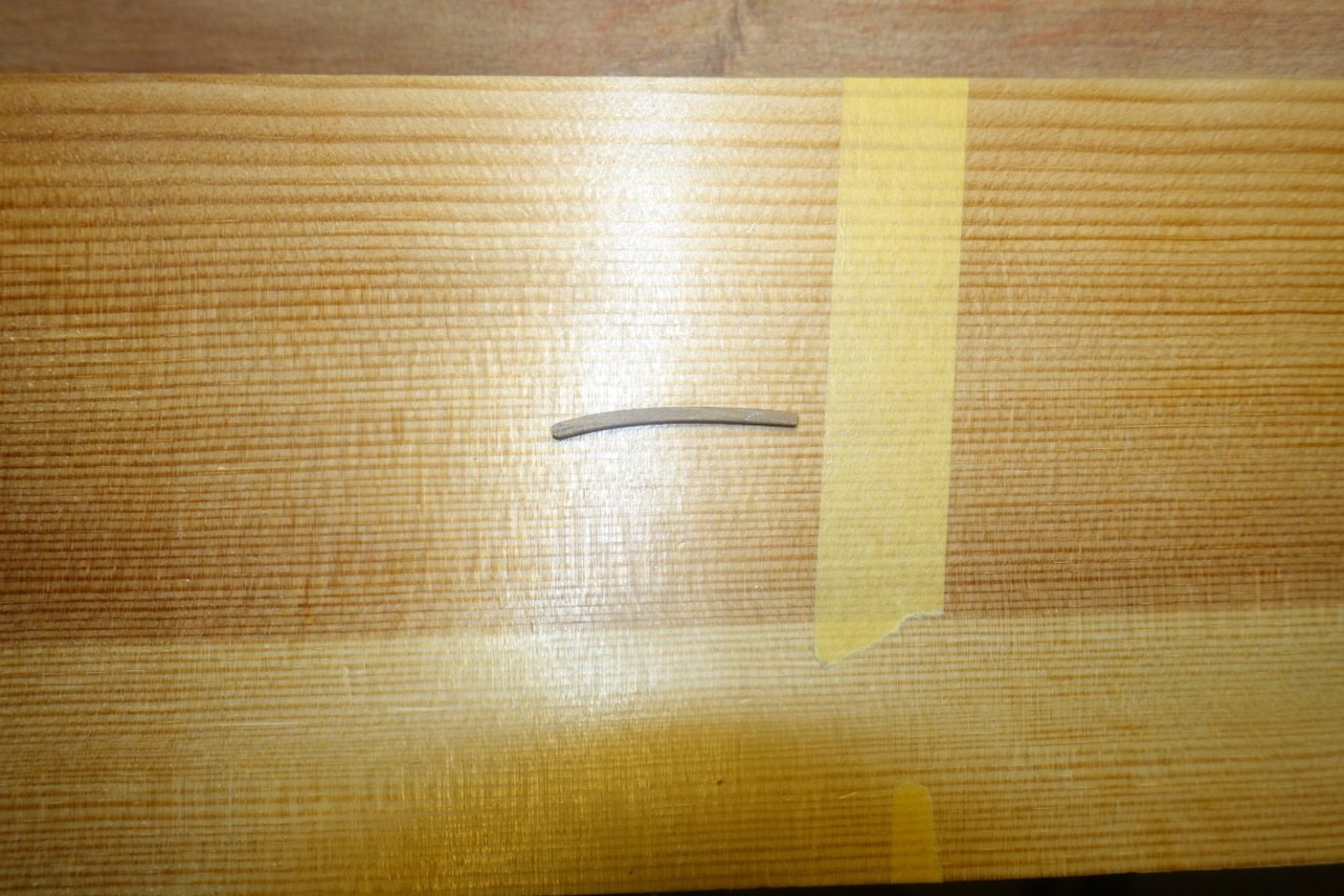
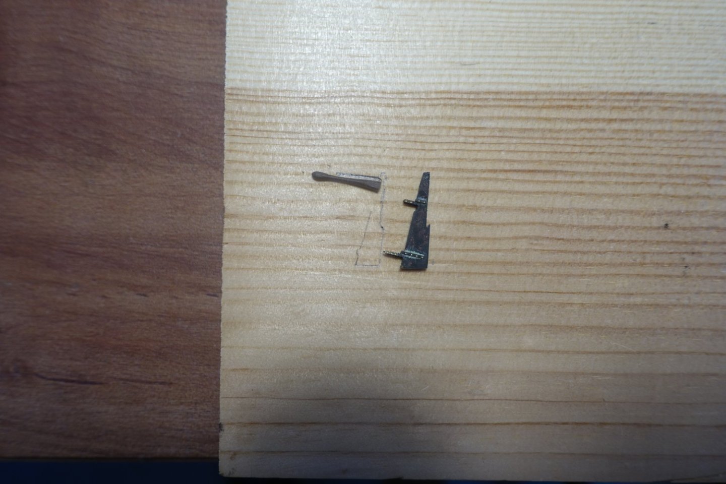
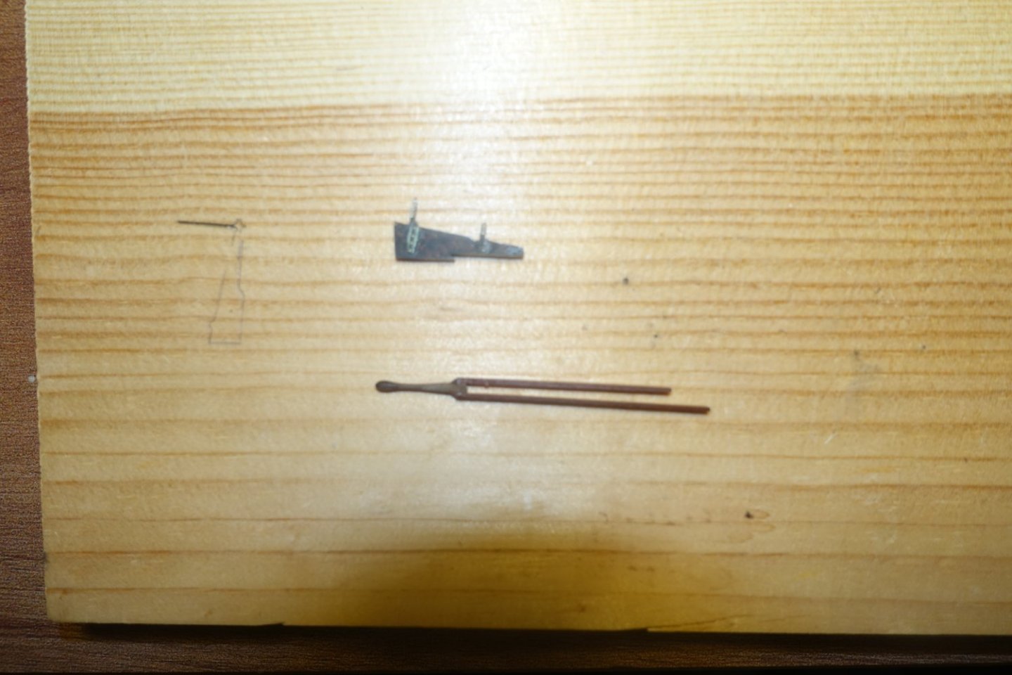
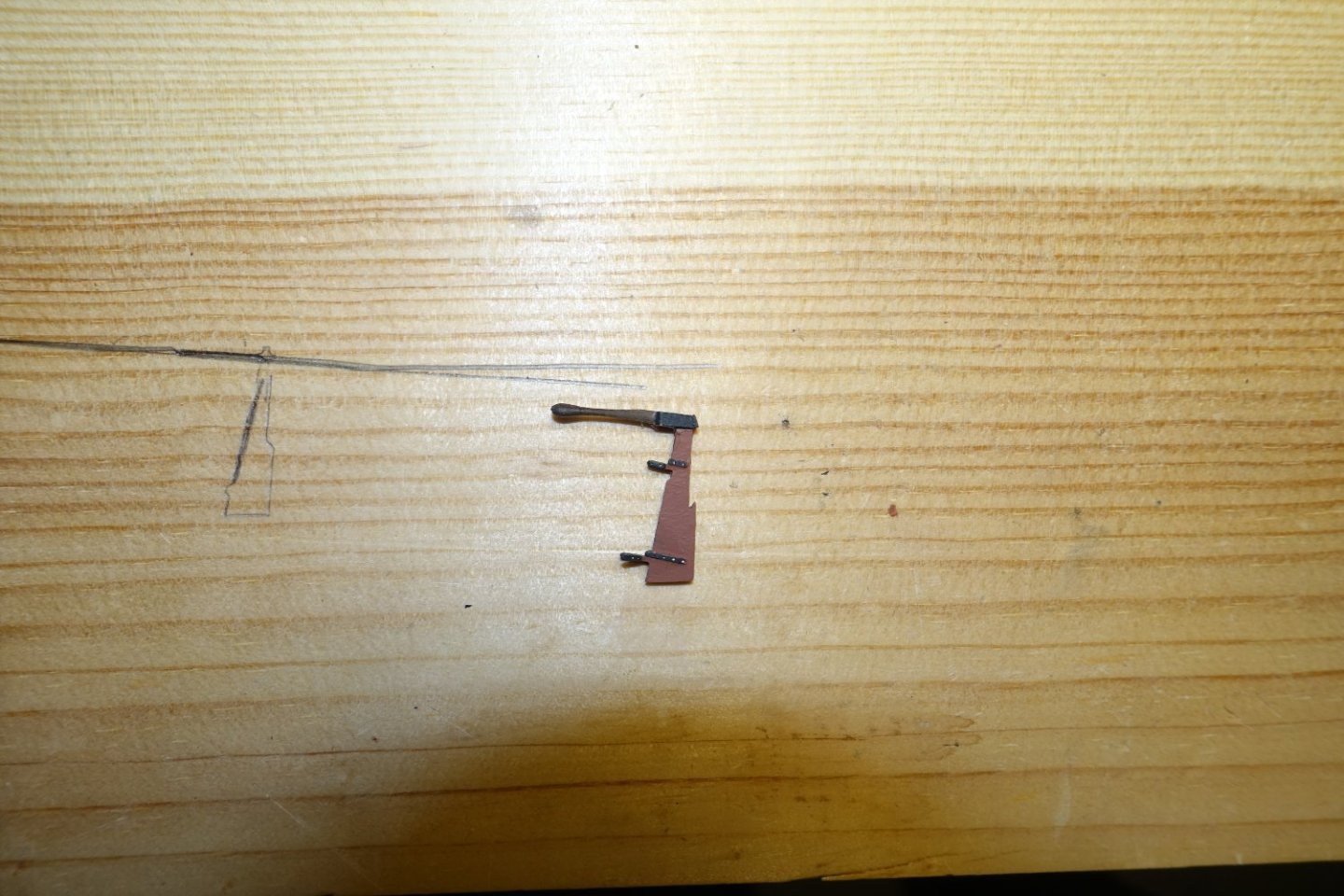
Davit and rudder I didn't quite like the davit from the kit, since it seemed to fragile. So I bent a 2 x 2 mm strip and sanded it to size. Davit with brass rod " sheave ". I made a rudder tiller from a 2x2mm strip, which I sanded accordingly The tiller was filed to the width of the rudder and the bevel adjusted. In the picture, the brass rudder cover has already been treated with a blackening solution acting quickly. Two remaining pieces of the sit support strips were glued to the sides of the tiller Once dry, the rudder was fitted in the strips. A transverse strip was added at the back, the rudder was painted with mahogany wood paint, the rudder hinges and the tiller hinge black. Rudder and davit are attached and secured.


- 20 replies
-
- 2
-
-
- 24 ft Launch
- Vanguard Models
- (and 1 more)
-
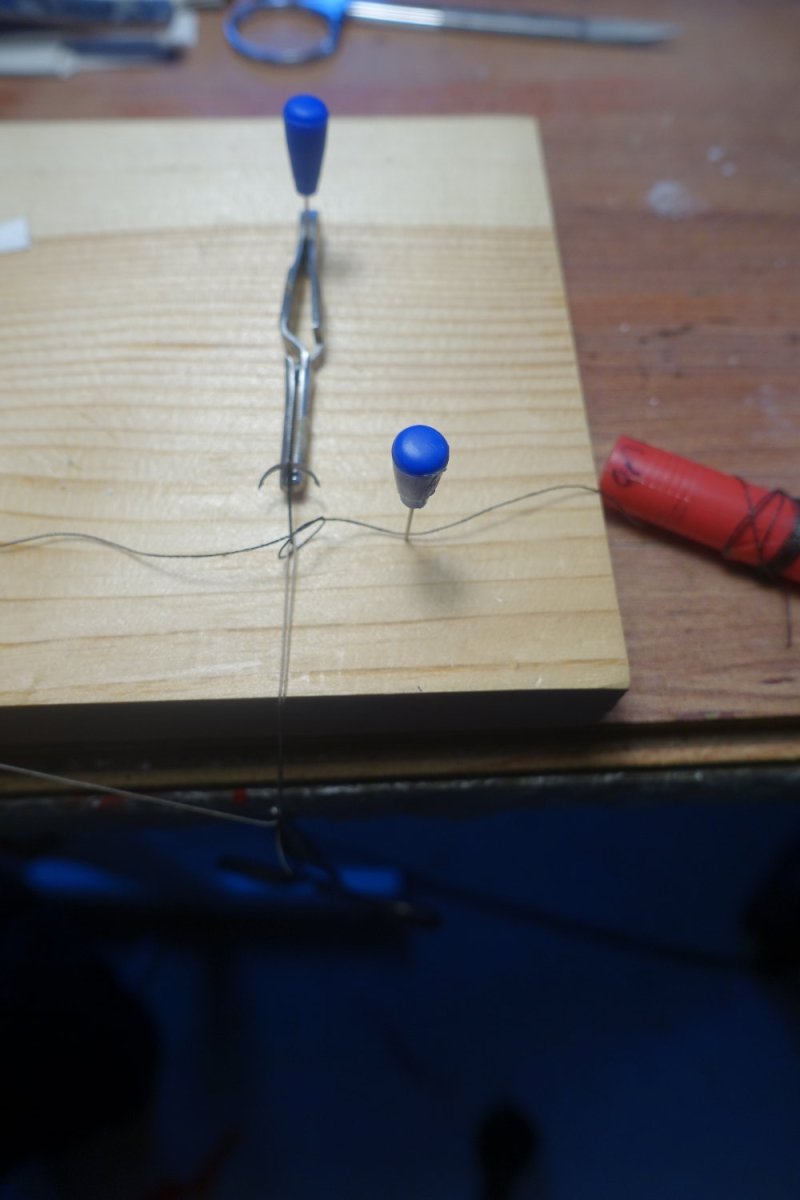
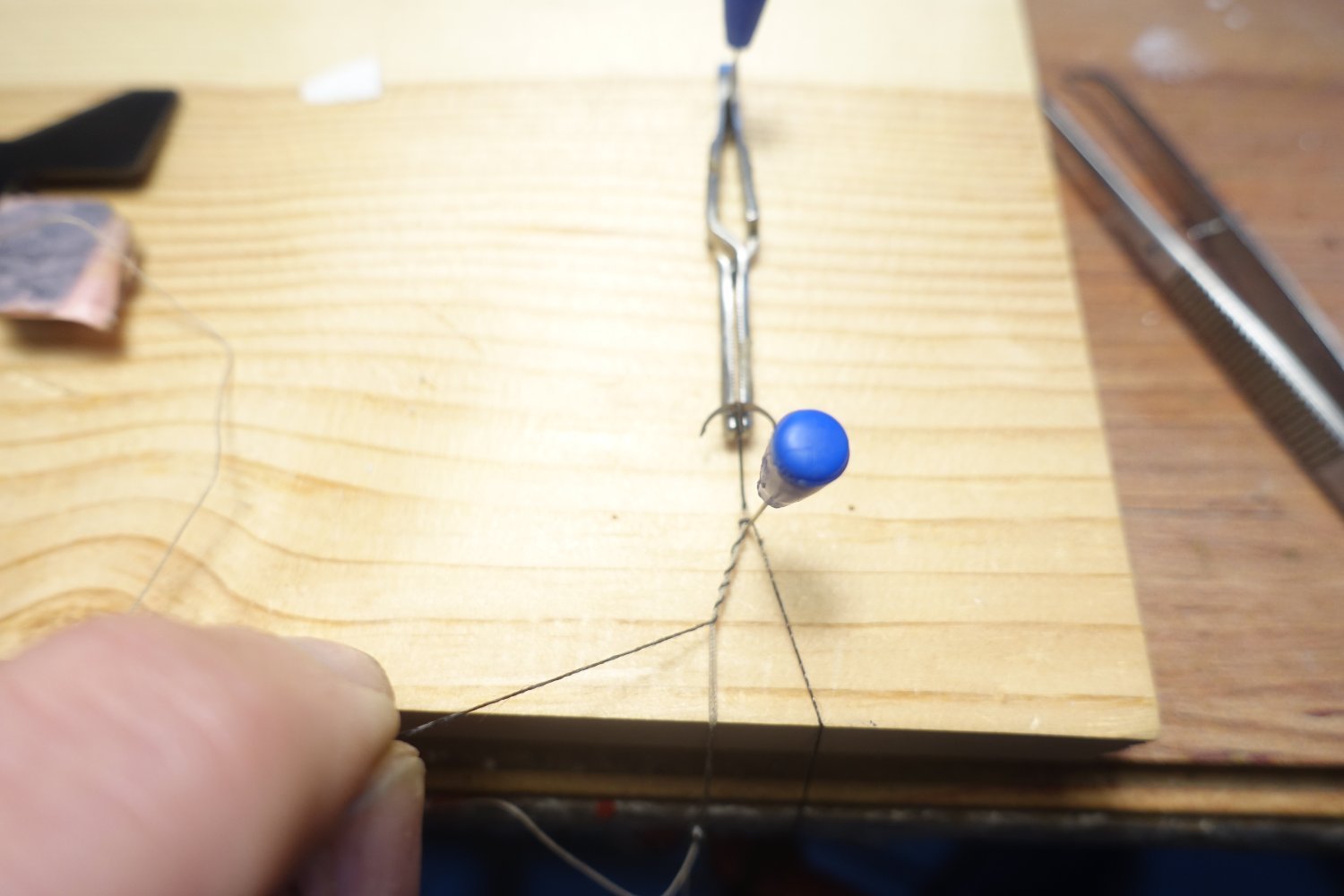
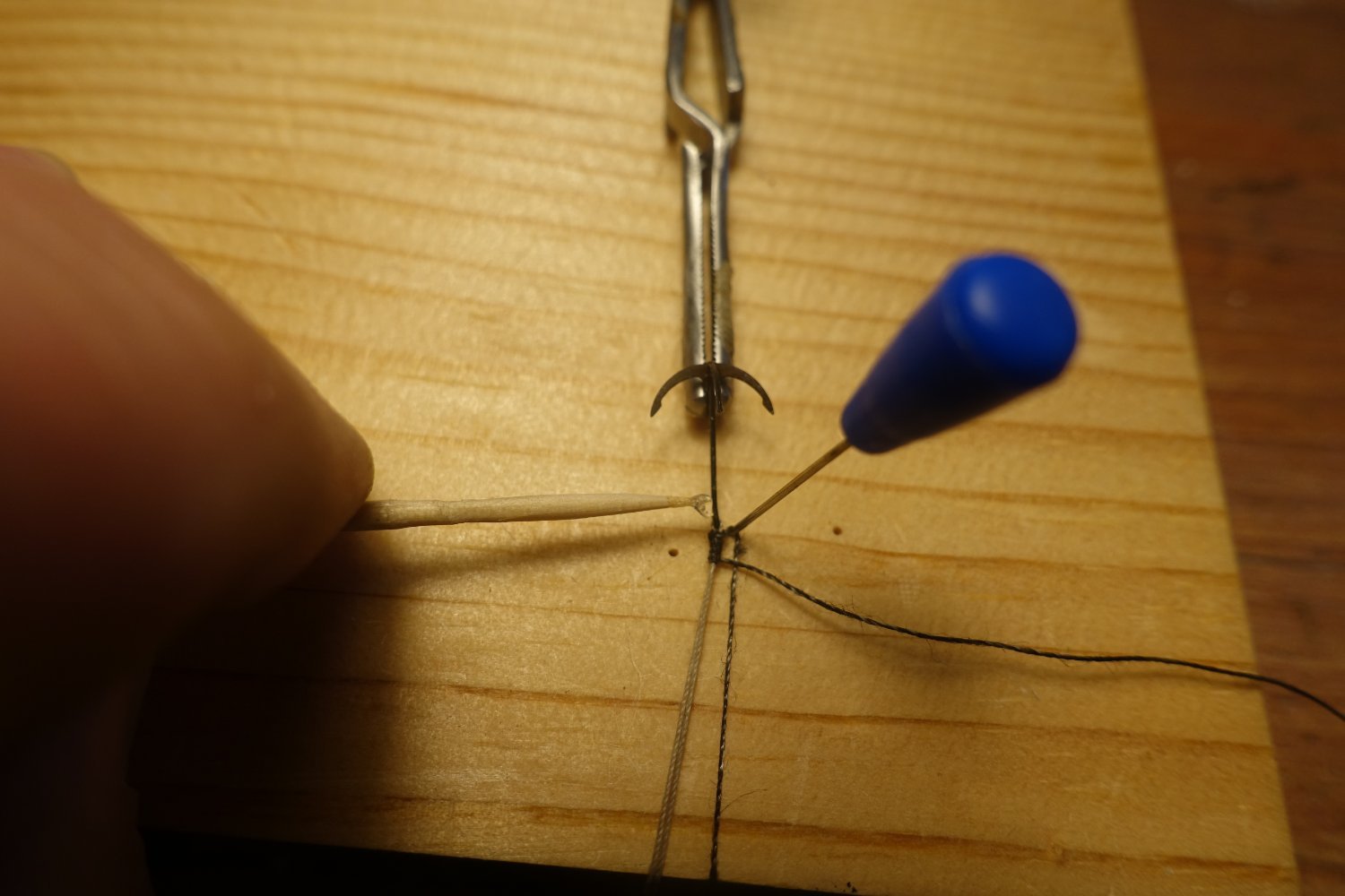
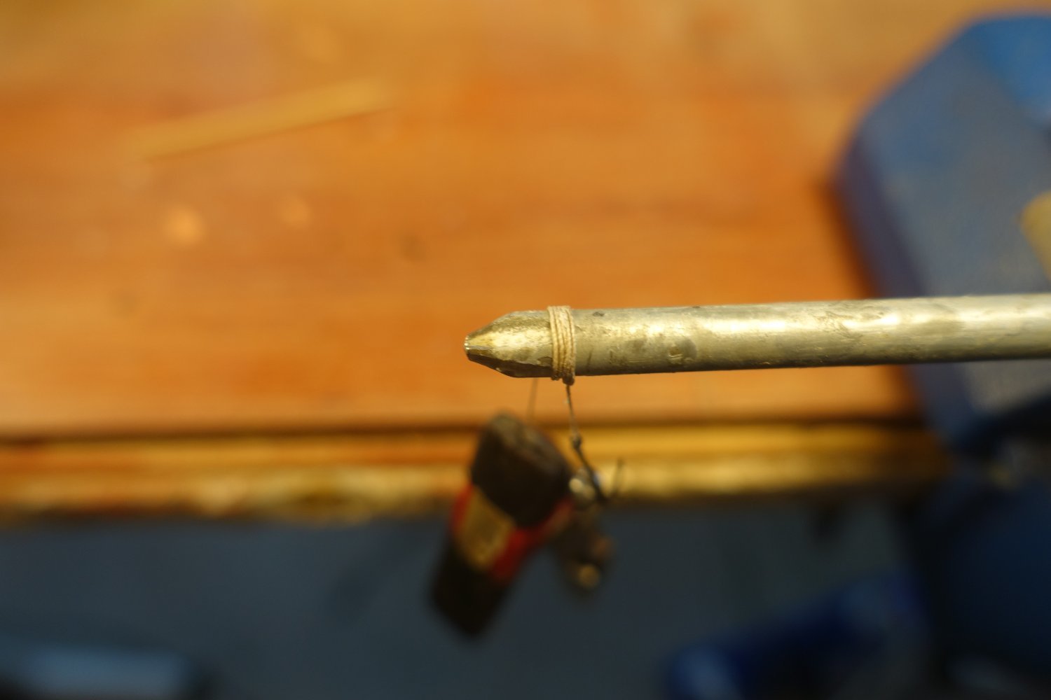
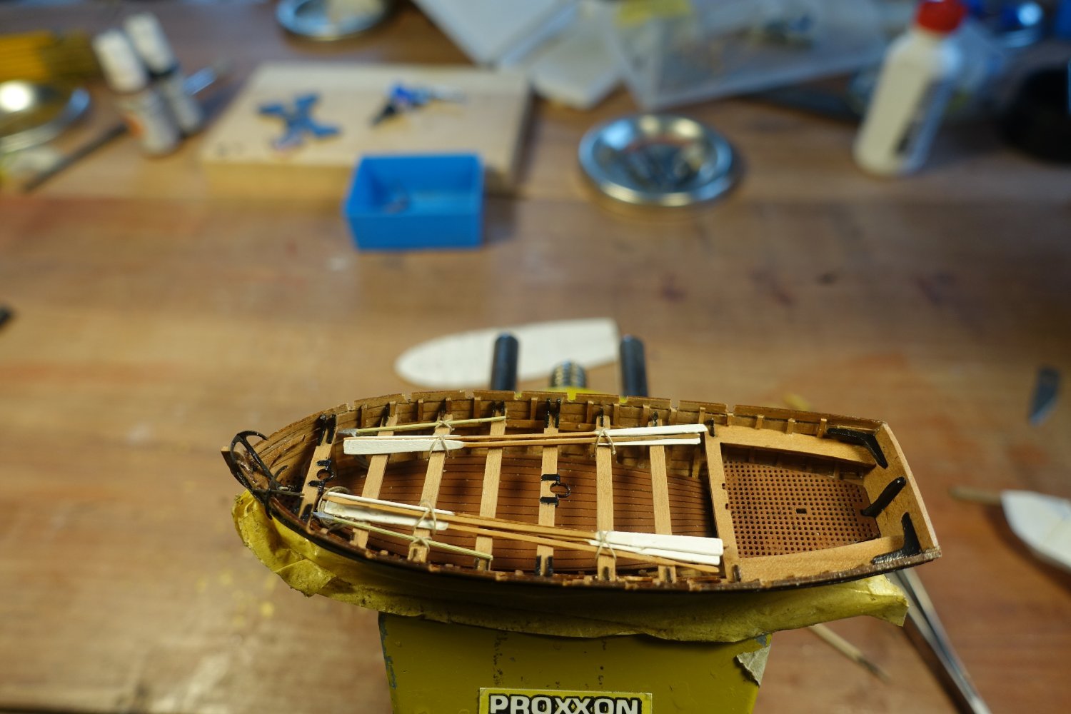
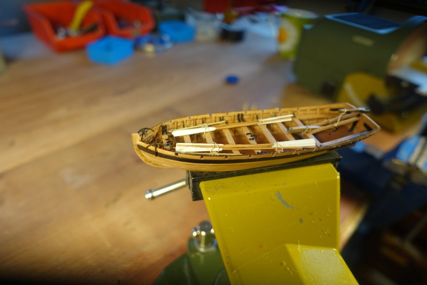
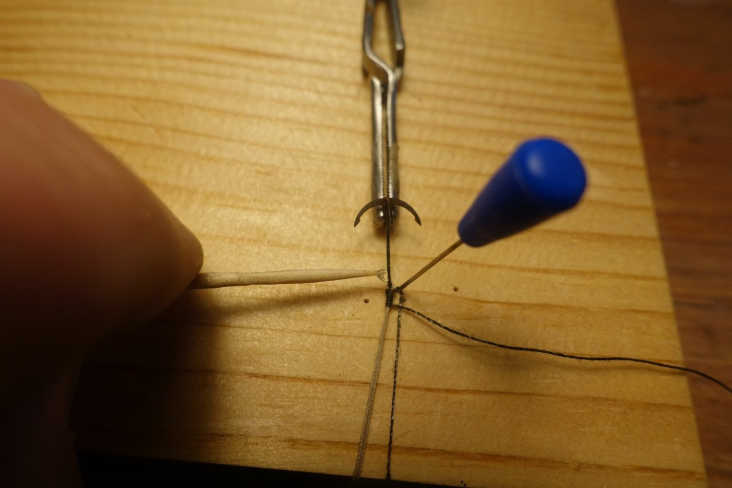
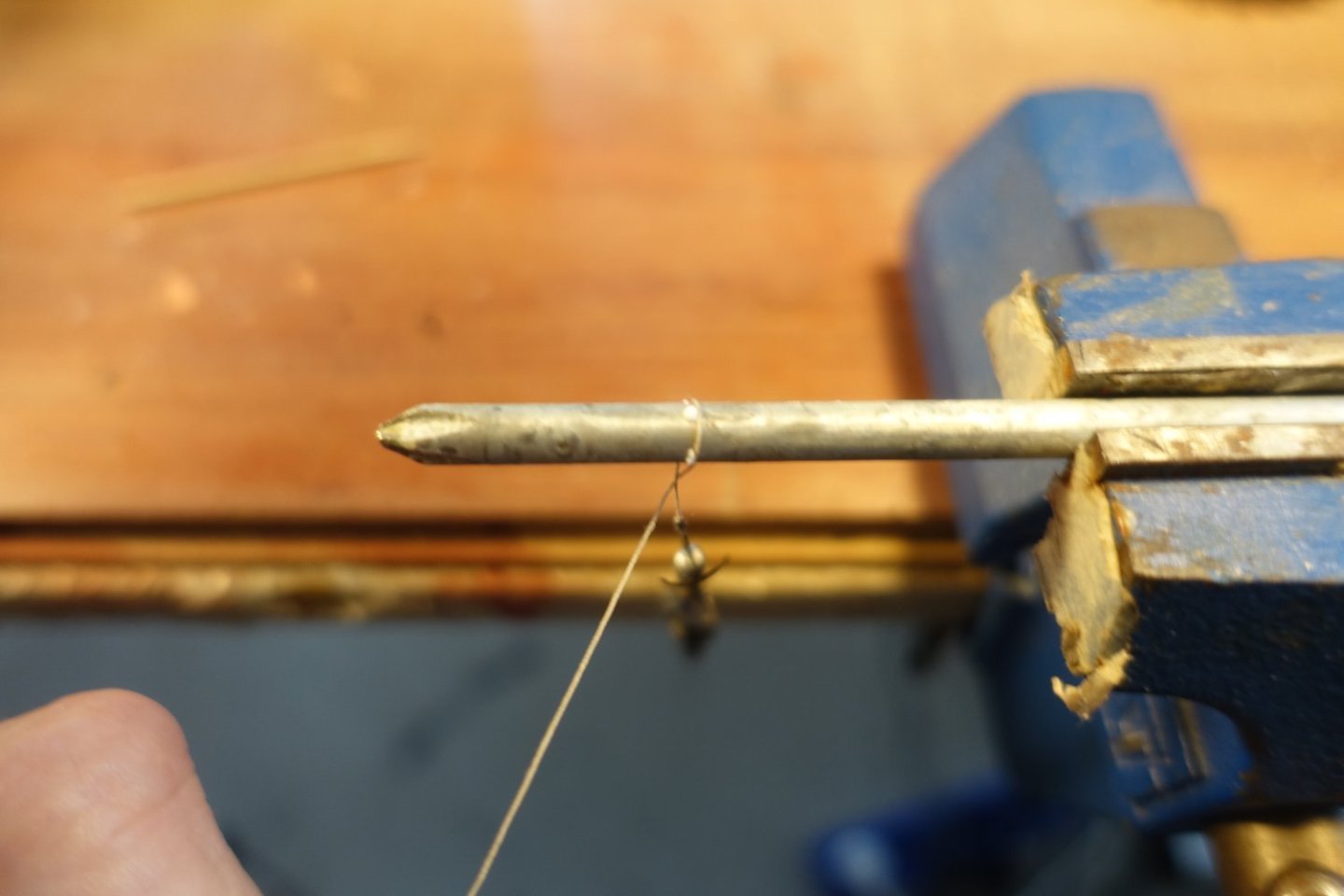
Anchors, oars and hooks Anchors were supplied with a rope. I used a screwdriver to roll up the anchor rope, put some PVA on the rod and then wrapped the anchor rope around it. The anchors were stored in the bow area. Oars and grappling hooks were secured on the thwarts.


- 20 replies
-
- 2
-
-
- 24 ft Launch
- Vanguard Models
- (and 1 more)
-
Gunwale and rubbing strake The gunwale was glued on with PVA (attachment to the bow: CA). The slightly protruding ribs made it easy to align it with the lower hull wall. The recesses for the oars were sanded in. The rubbing strakes were fitted.
- 20 replies
-
- 1
-
-
- 24 ft Launch
- Vanguard Models
- (and 1 more)
-
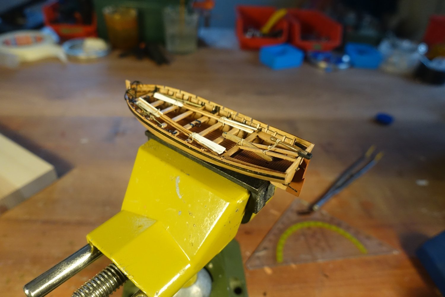
Thwarts The thwarts were attached to the supports. A 1x7mm strip was used as a spacer between the thwarts. Where ribs met the middle of the thwarts, I removed the rib section above the supports. Later, knees have to be attached in the middle of the thwarts, which may come into conflict with the ribs. It is not shown on the plan, but Chris has prepared two mast brackets on the brass sheet. Unfortunately, one of them was swallowed by the carpet monster. Therefore I made a replacement from a brass bar of the brass sheet Short pieces of ribs were glued to the rear seats. The kit includes 20 knees for the thwarts. According to Chris' plan, however, 7x4 + 2, i.e. 30 knees, are required. Even if you only use two knees per thwart, that's still 16 knees, so there's not much in reserve. I painted the knees black at first. The knees are attached. For the thwarts with the mast brackets, I used two knees on each side taken from the wood sheet of the pinasse (also part of the Sphinx kit). There are really quite few knees provided for the launch on the wood sheet. One Launch knee snapped off and I couldn't find it again.


- 20 replies
-
- 2
-
-
- 24 ft Launch
- Vanguard Models
- (and 1 more)
-
The thwarts were attached to the supports. A 1x7mm strip was used as a spacer between the thwarts. Where ribs met the middle of the thwarts, I removed the rib section above the supports. Later, knees have to be attached in the middle of the thwarts, which may come into conflict with the ribs. It is not shown in the instructions and also not on the plan, but Chris has prepared two mast brackets on the brass sheet. Unfortunately, one of them was swallowed by the carpet monster. Therefore I made a replacement from a brass bar of the brass sheet. Short pieces of ribs were glued to the rear seats. The kit includes 20 knees for the thwarts. According to Chris' plan, however, 7x4 + 2, i.e. 30 knees, are required. Even if you only use two knees per thwart, that's still 16 knees, so there's not much in reserve. I painted the knees black at first. The knees are attached. For the thwarts with the mast brackets, I used two knees on each side taken from the wood sheet of the pinasse (also part of the Sphinx kit). There are really quite few knees provided for the launch on the wood sheet. One Launch knee snapped off and I couldn't find it again.


- 20 replies
-
- 5
-
-
- 24 ft Launch
- Vanguard Models
- (and 1 more)
-
Thank you very much for the encouraging words. Once you get to grips with the peculiarities of these small boats, it really is a pleasure to build them. Clark
-
Thank you very much. I found the suggested method of pencil markings too imprecise, as the distance to the edge is difficult to mark. Clark
-
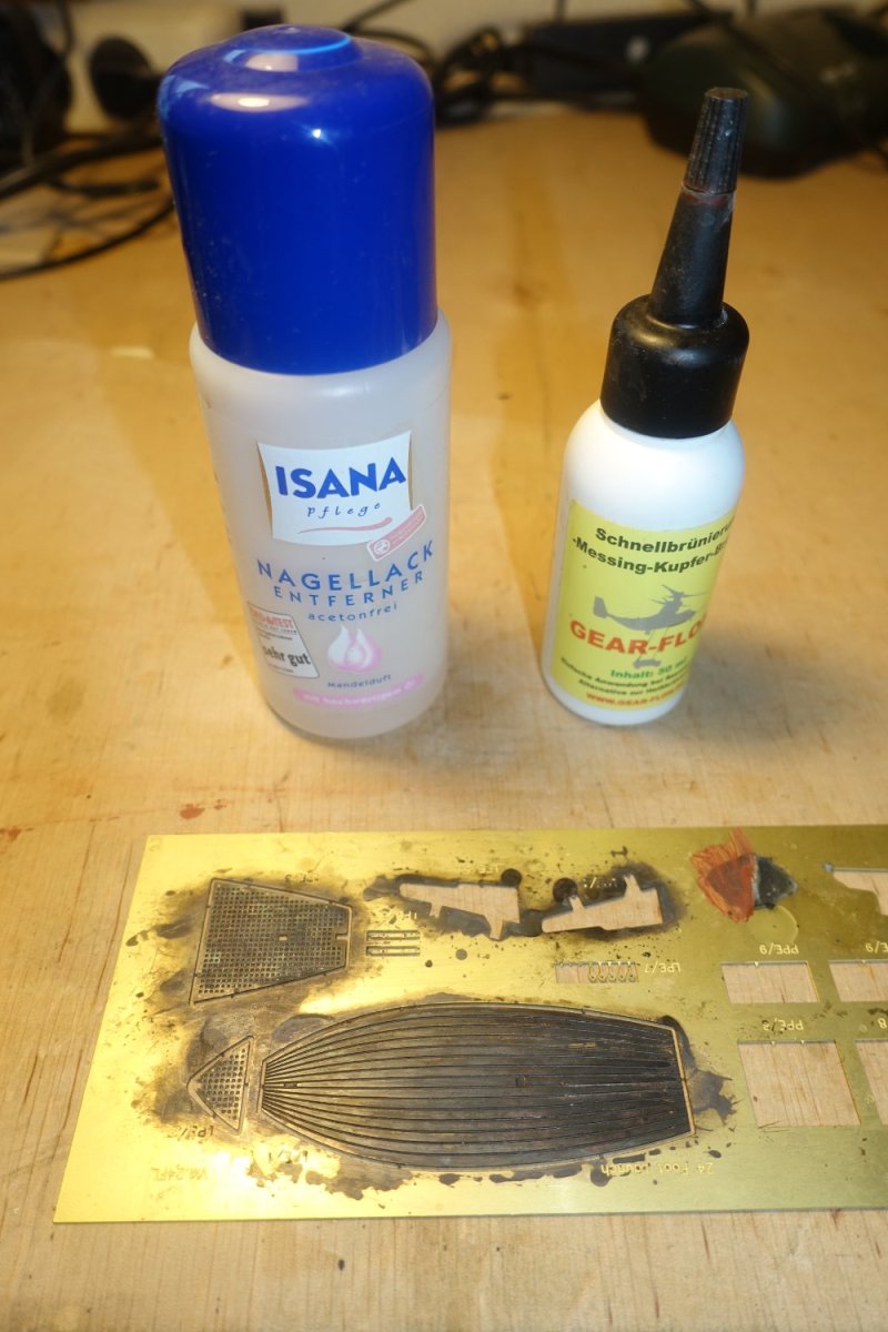
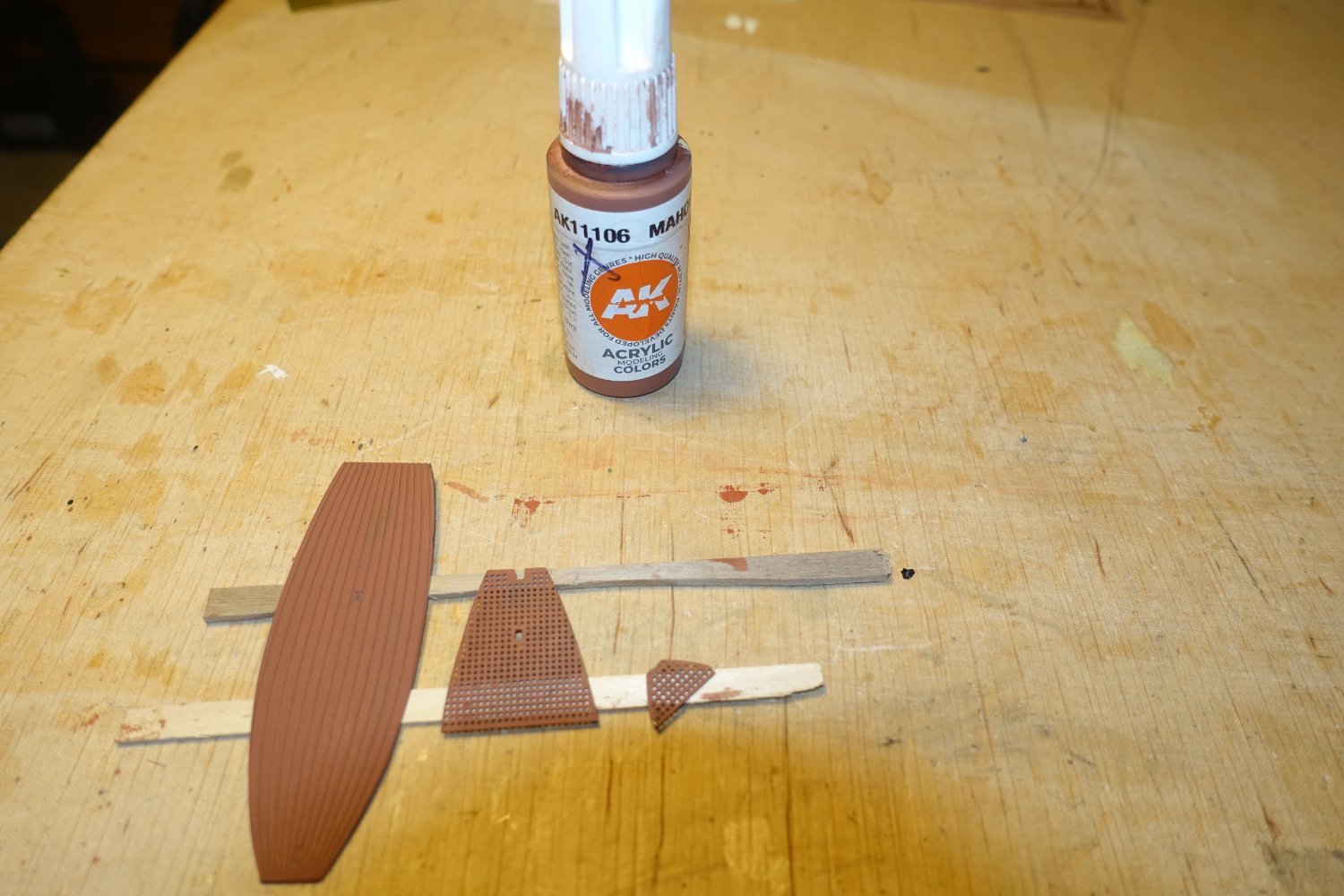
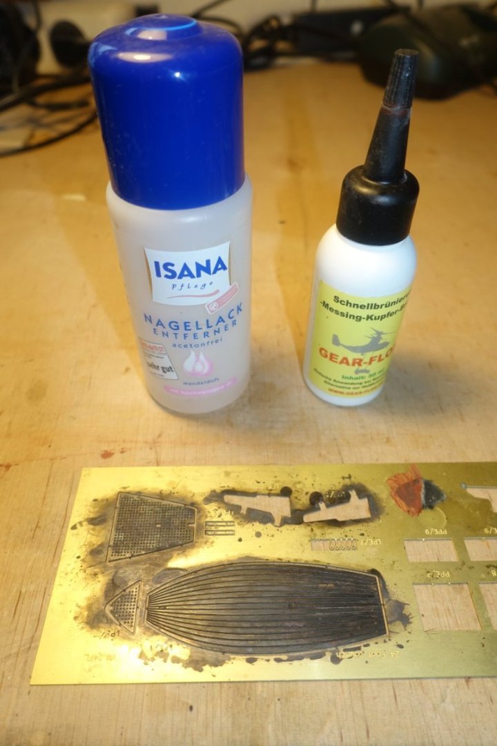
Just a short update: preparation of floor The brass floor was first cleaned with nail polish remover and then treated with a blackening solution acting quickly. This type of solution does not produce such good results for blackening, but it does provide a base for subsequent painting. The "floorboards" were then painted mahogany.

- 20 replies
-
- 4
-
-
- 24 ft Launch
- Vanguard Models
- (and 1 more)
-
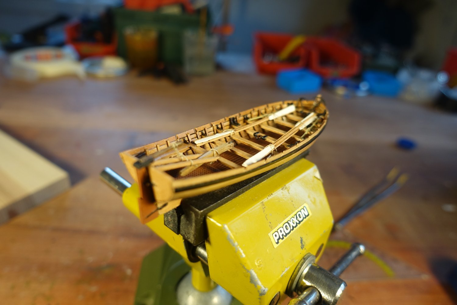
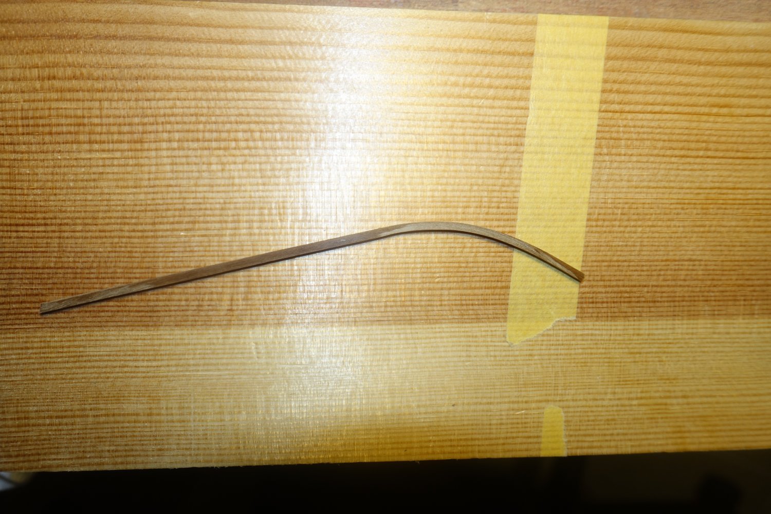
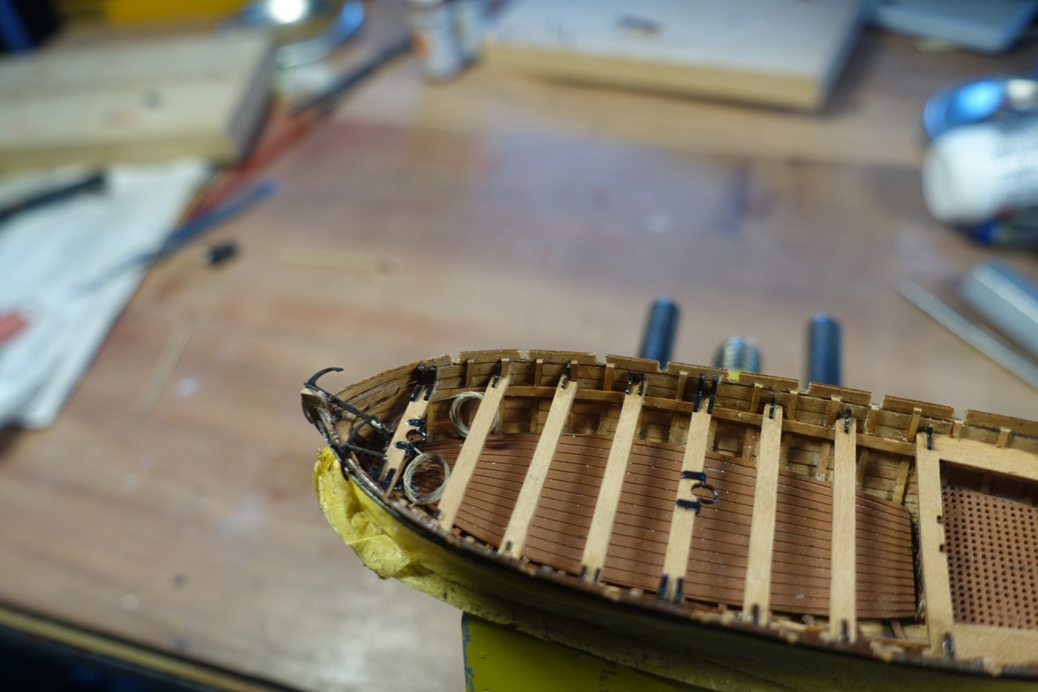
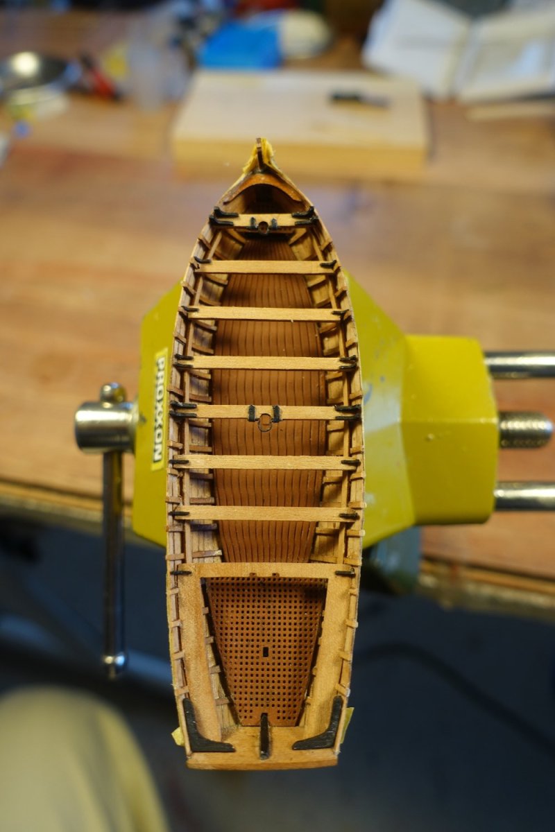
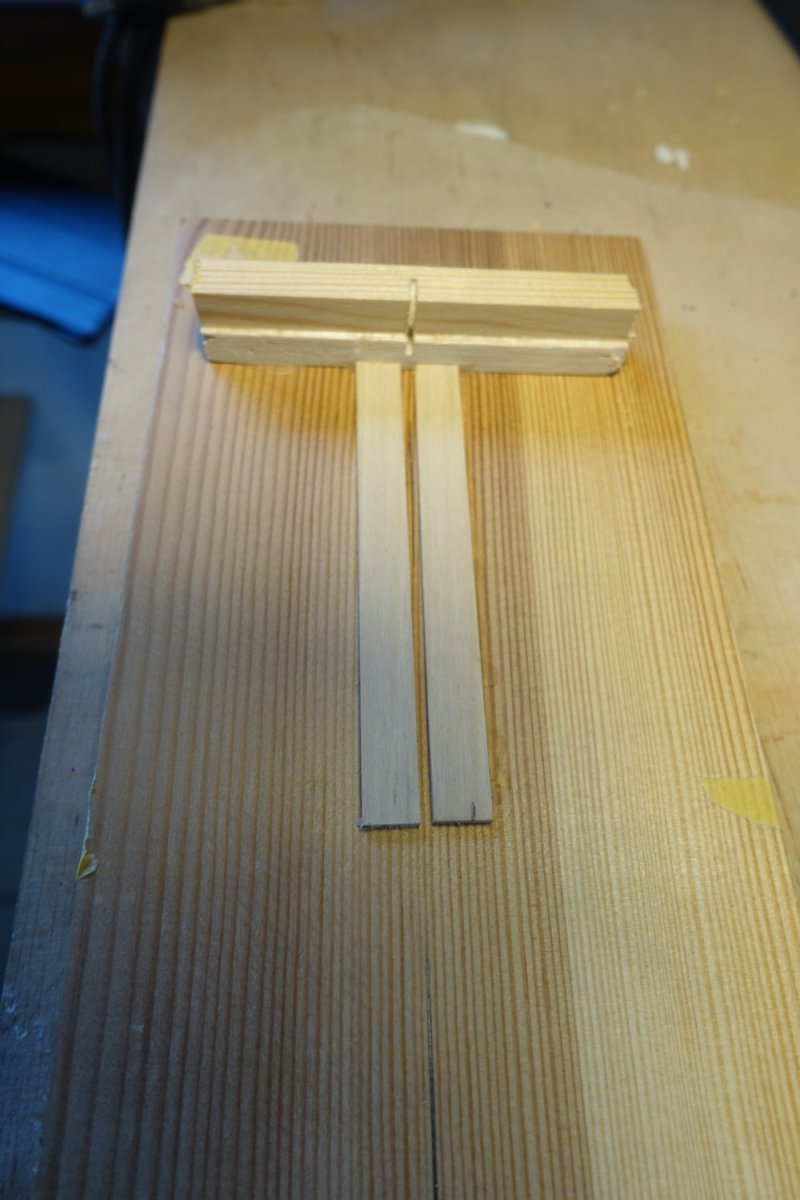
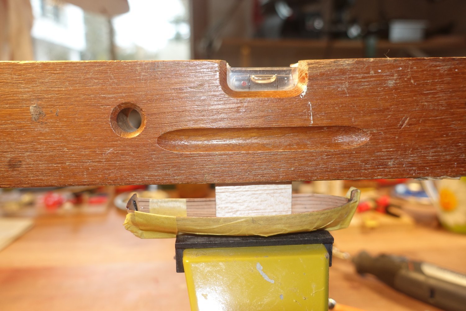
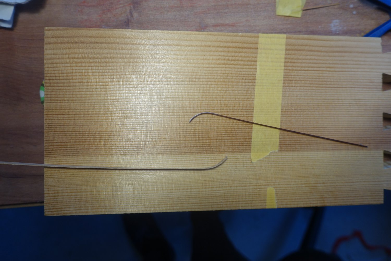
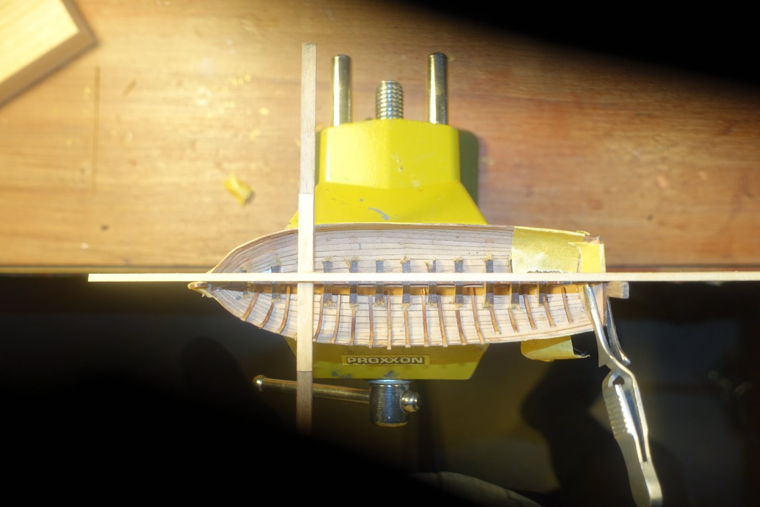
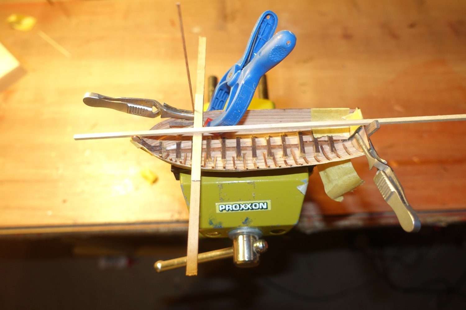
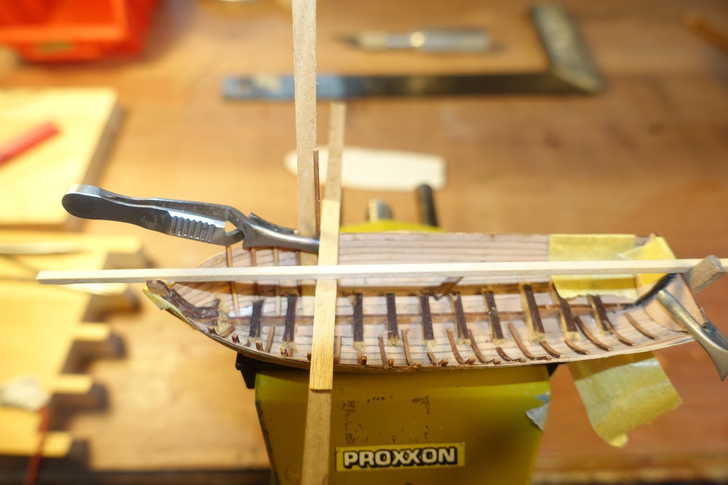
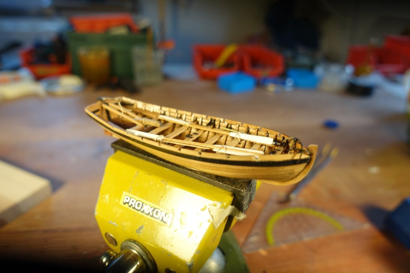
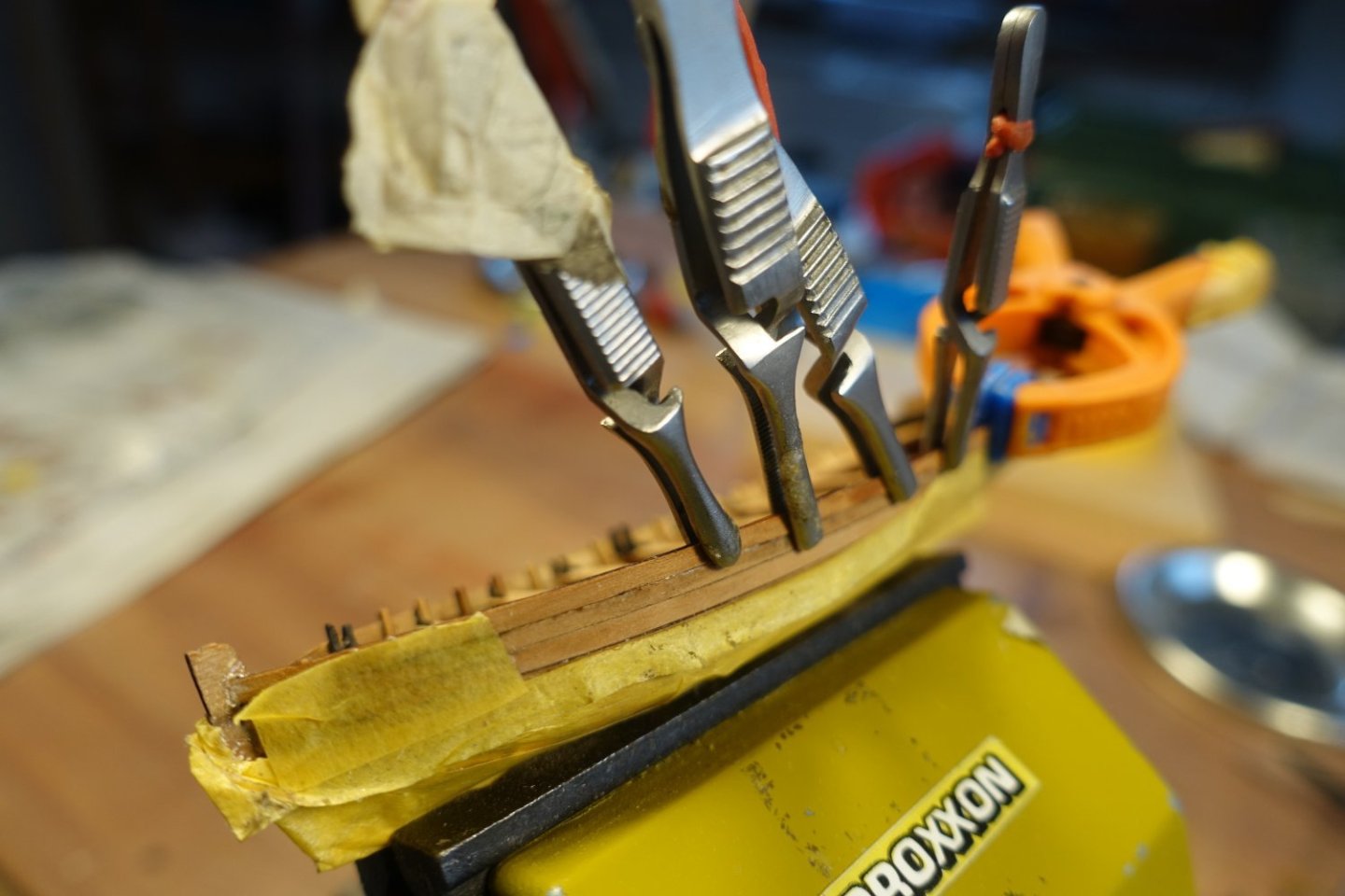
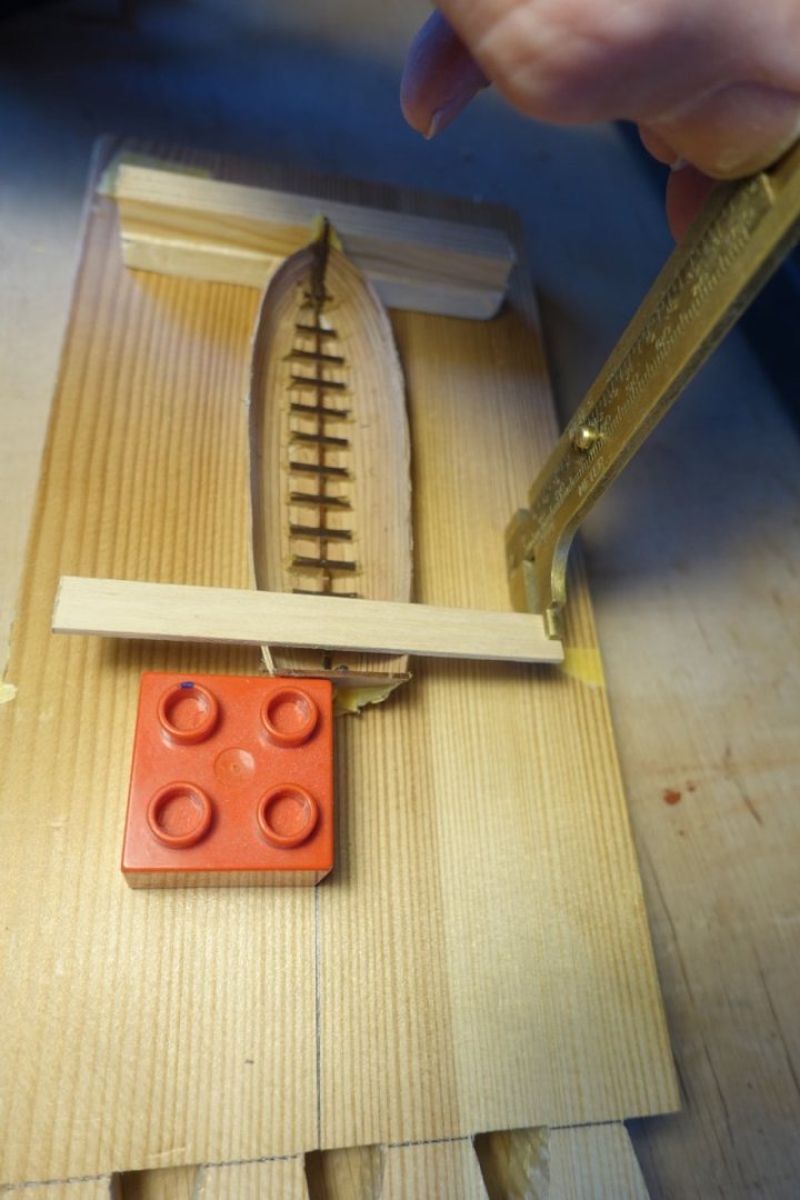
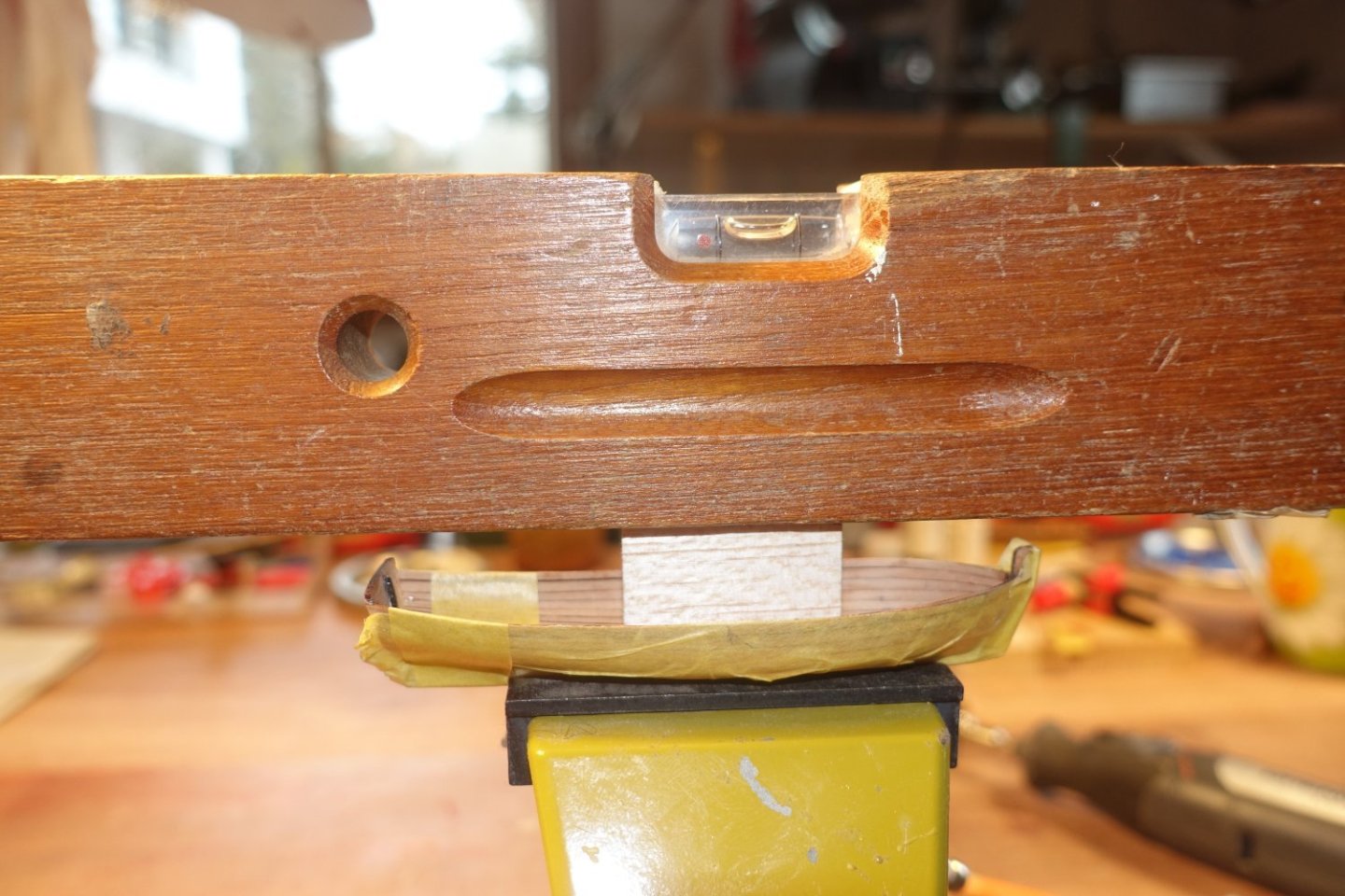
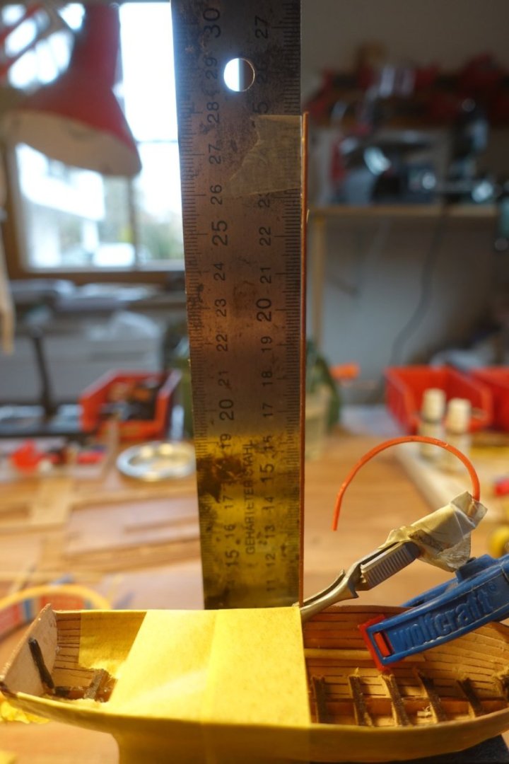
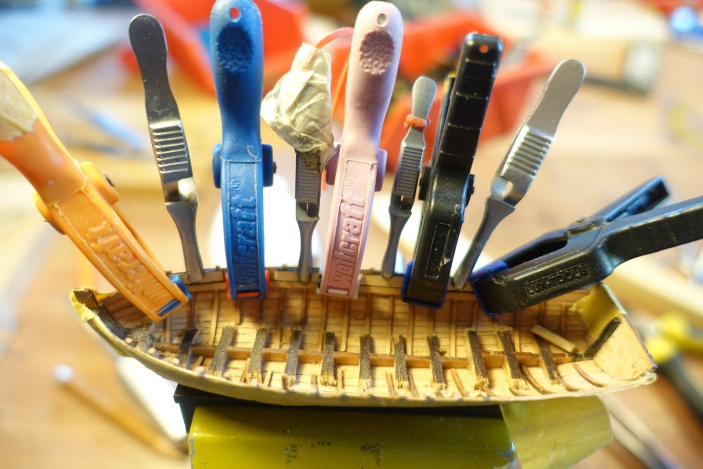
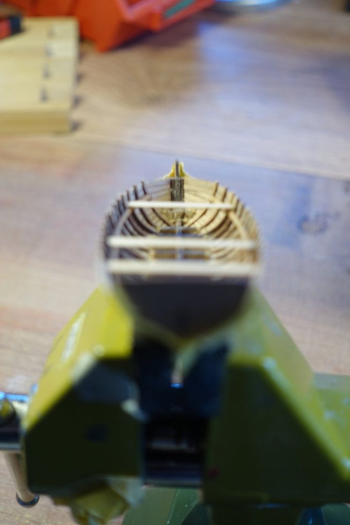
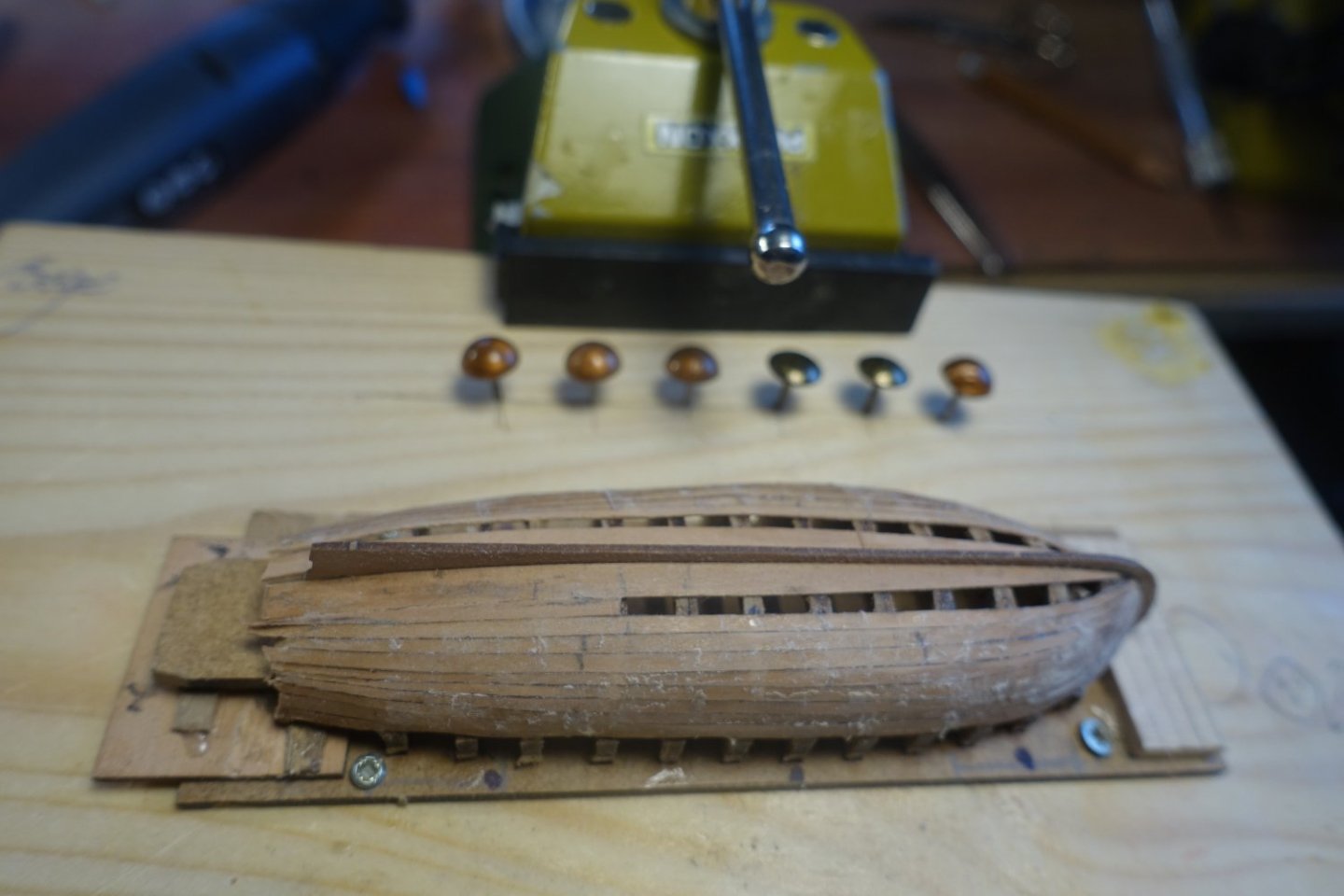
Ribs To level the starboard and port sides, I made a simple mini shipyard. The launch is clamped in it, the vertical alignment is checked using a Duplo brick, which is brought into line with the sternpost. The distance to the bottom board is measured on both sides of the boat using a strip laid over the edges of the hull and the edge of the hull is sanded very lightly (!) if necessary. A minimal correction was only necessary in the stern area on the port side. The boat was leveled along its longitudinal axis. The ribs were bent at their ends using heat (top). I did the same with a 0.5x5 mm strip, which will later serve as a spacer between the ribs (bottom). The first rib was attached with PVA, the vertical alignment was checked with the help of a right angle. The previously bent 0.5x5mm strip was placed against the first rib and the second rib was then placed against the 0.5x5mm strip and glued to the hull. To align the ribs on the starboard side to the same position as those on the port side, I built myself a small alignment aid. A 2x5mm strip was glued at right angles to a smaller strip. This smaller strip can then be aligned with the stem and sternpost, while the 2x5mm strip is inserted between the protrusions of the ribs on the port side. I let the ribs on the port side protrude about 2-3 mm over the edge of the hull. After all the ribs were attached, they were shortened. However, a 1mm overhang was left. The gunwale has to be fitted later. The overhang should serve to hold the gunwale in place. I used 3mm strips as spacers to attach the seat support strips at a distance of 3mm from the top of the bulwark. Using these strips as a guide, the seat support was glued on. After both supports had been fixed in this way, I checked again with strips laid across to see if the supports were correctly aligned.


- 20 replies
-
- 5
-
-
- 24 ft Launch
- Vanguard Models
- (and 1 more)
-
Even if you apply the PVA to the false deck, be careful with thinning. Let it dry slightly first. I made the same mistake. Clark
-
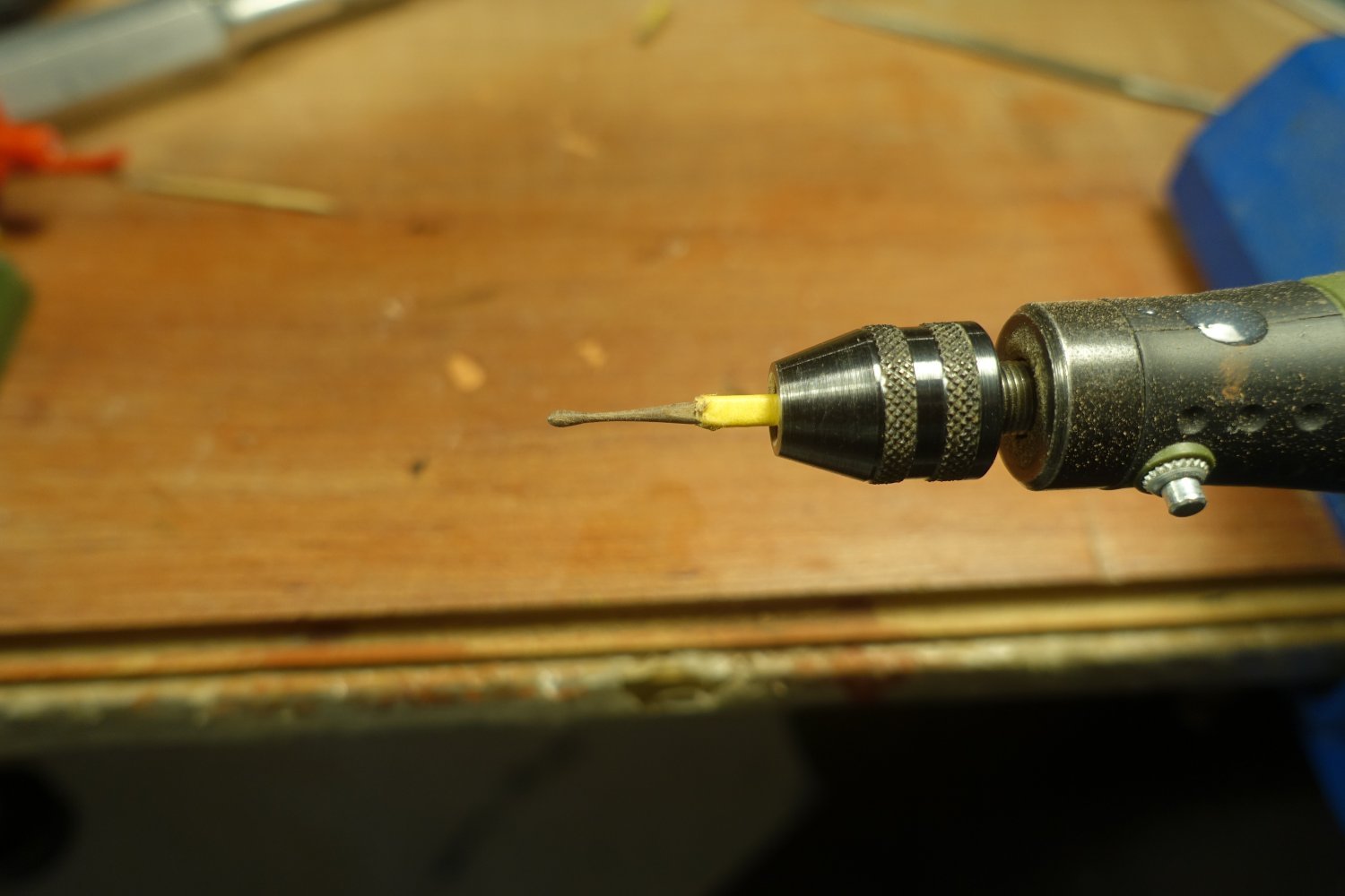
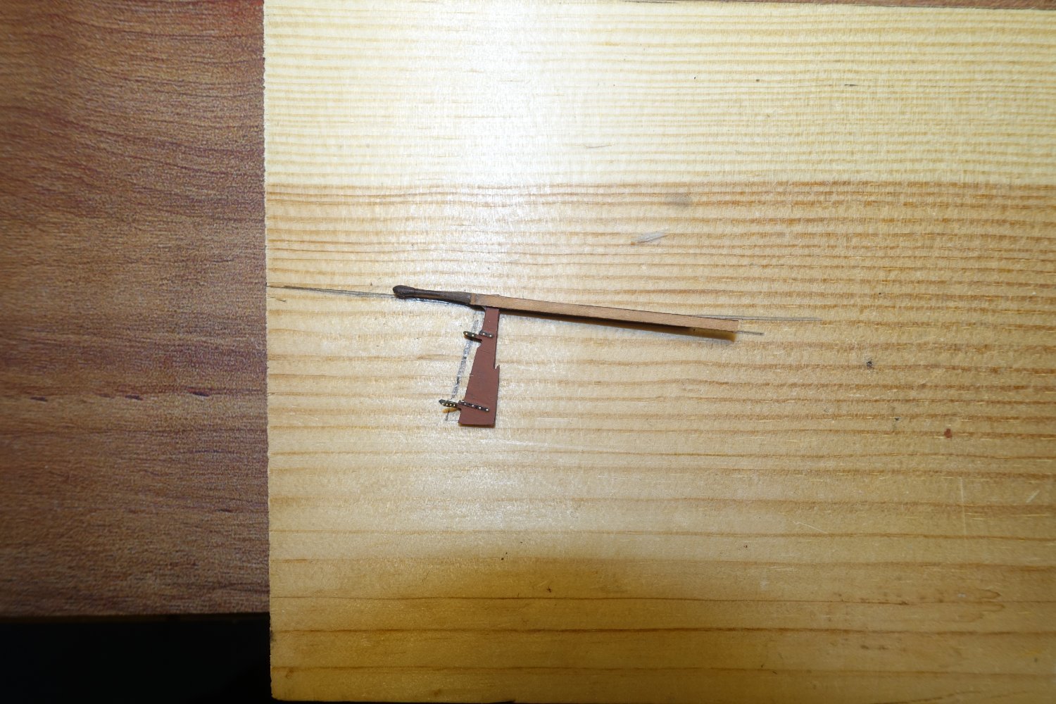
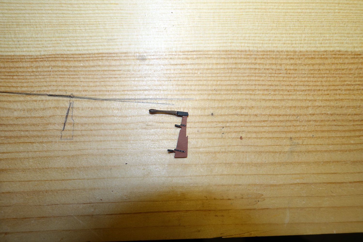
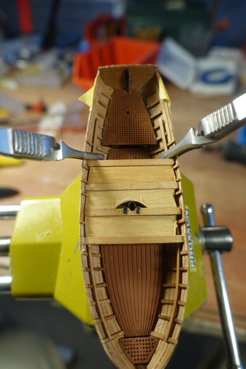
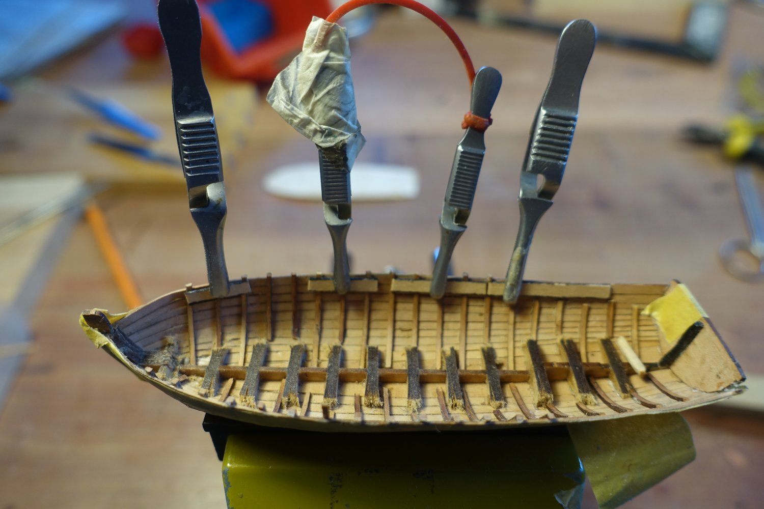
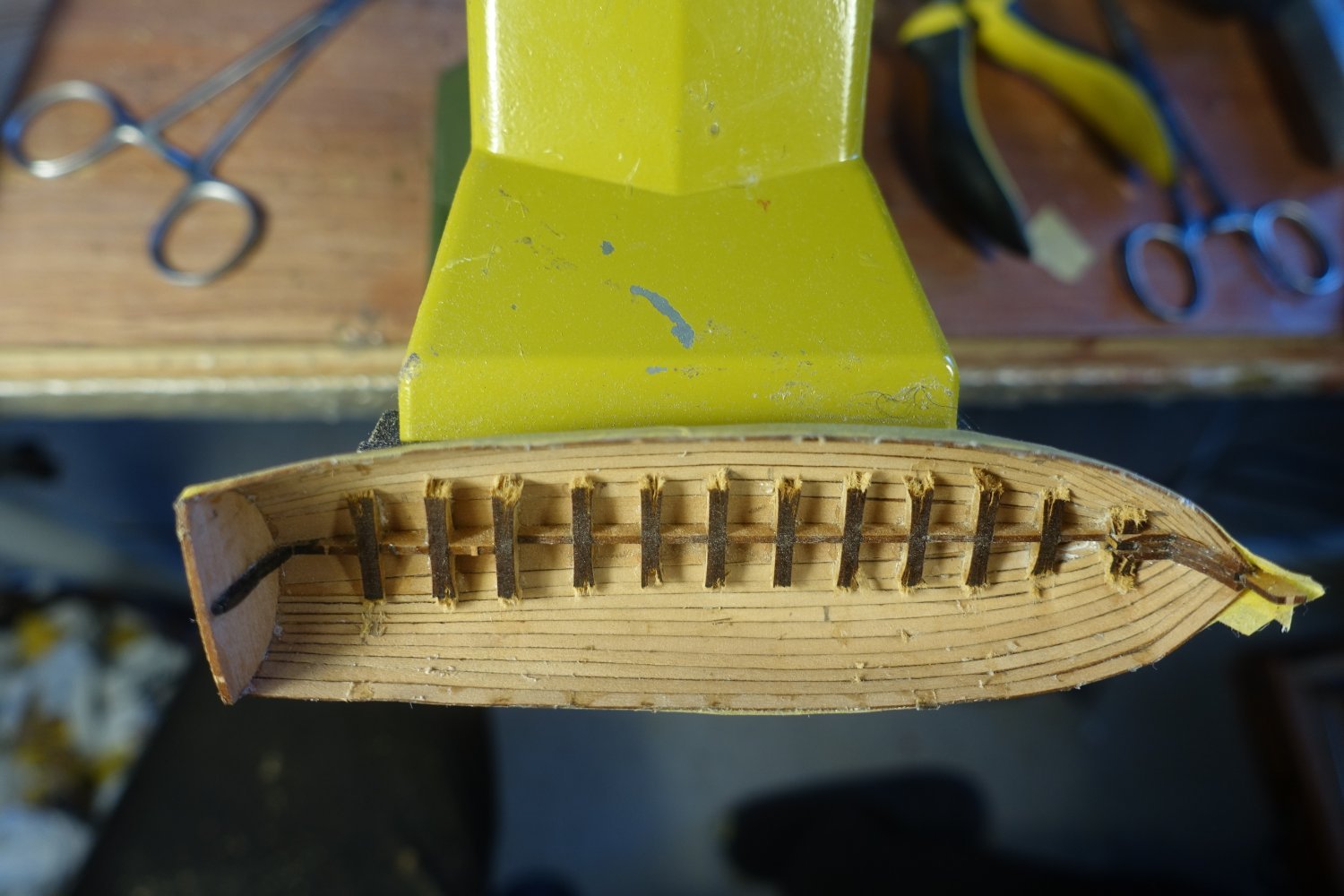
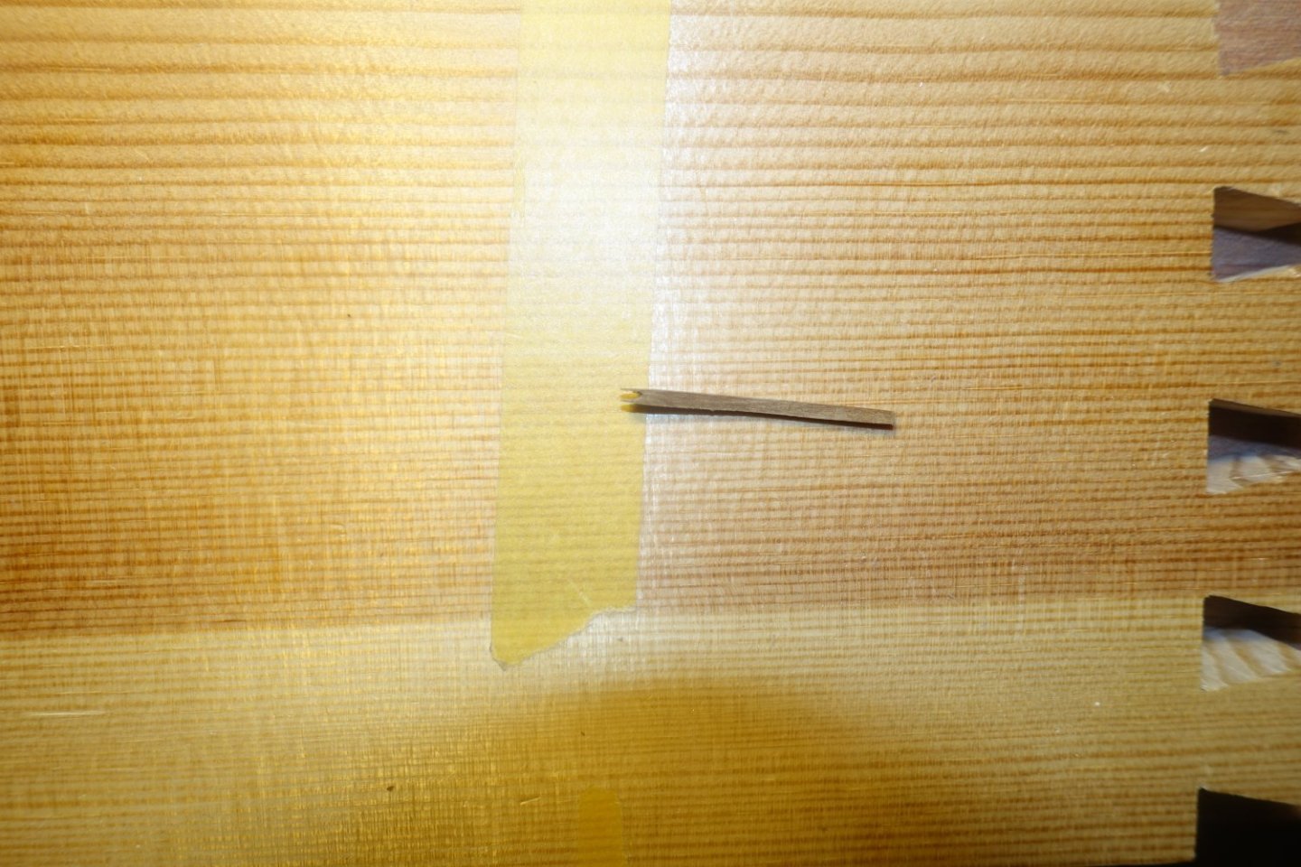
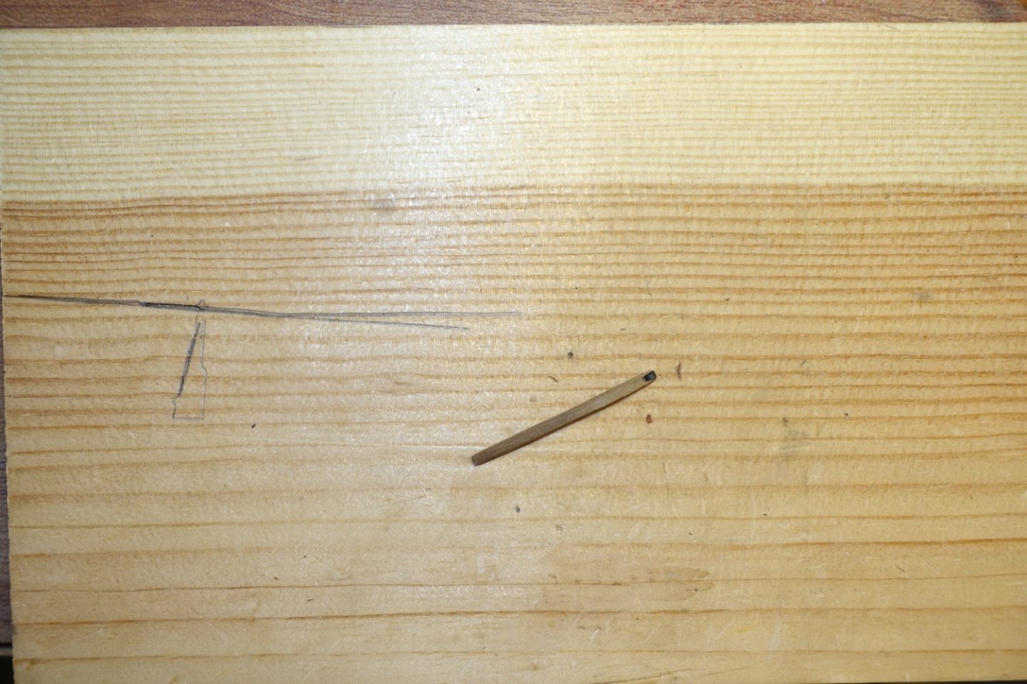
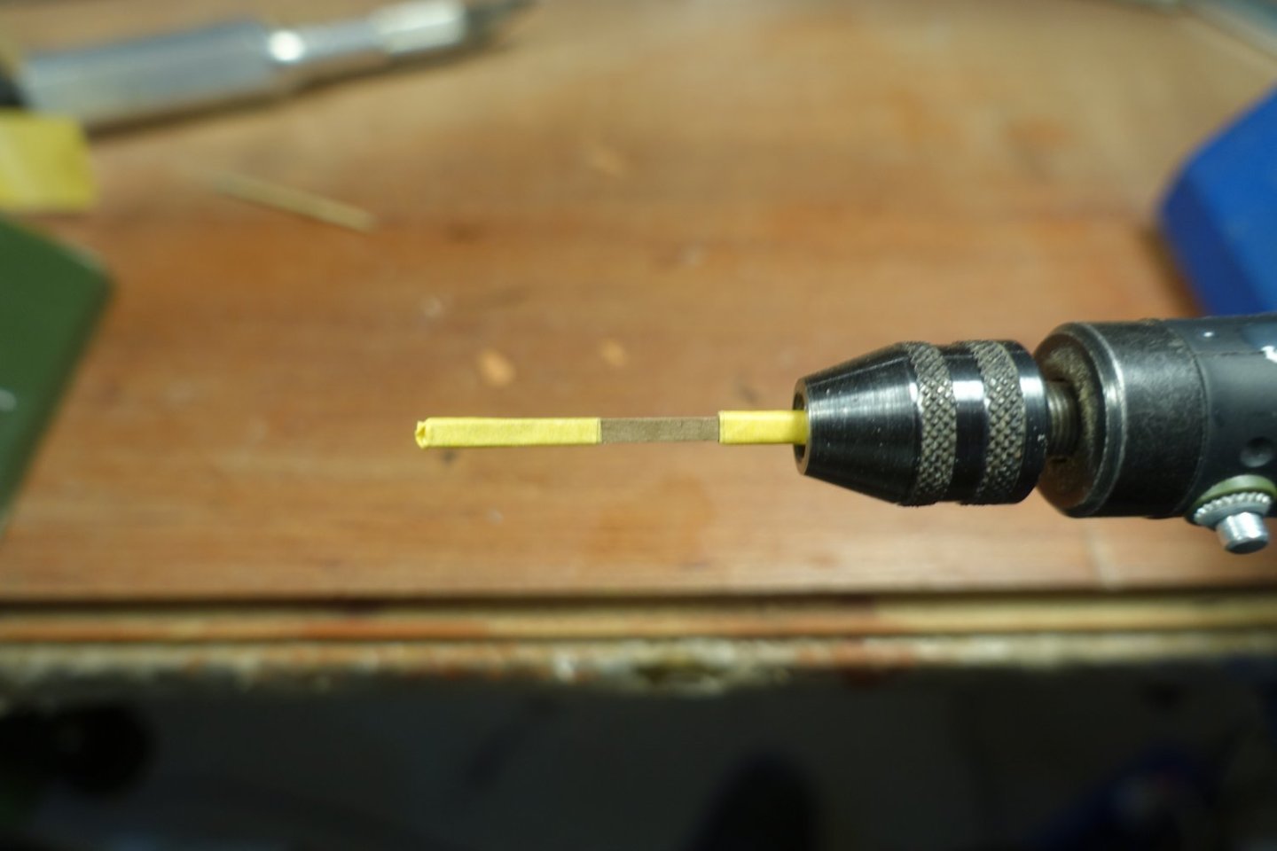
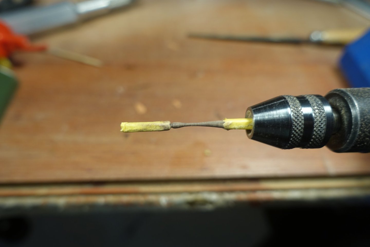
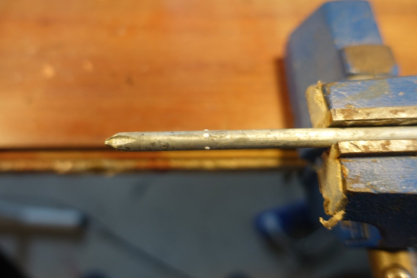
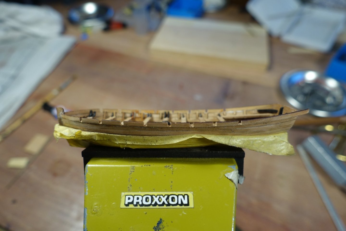
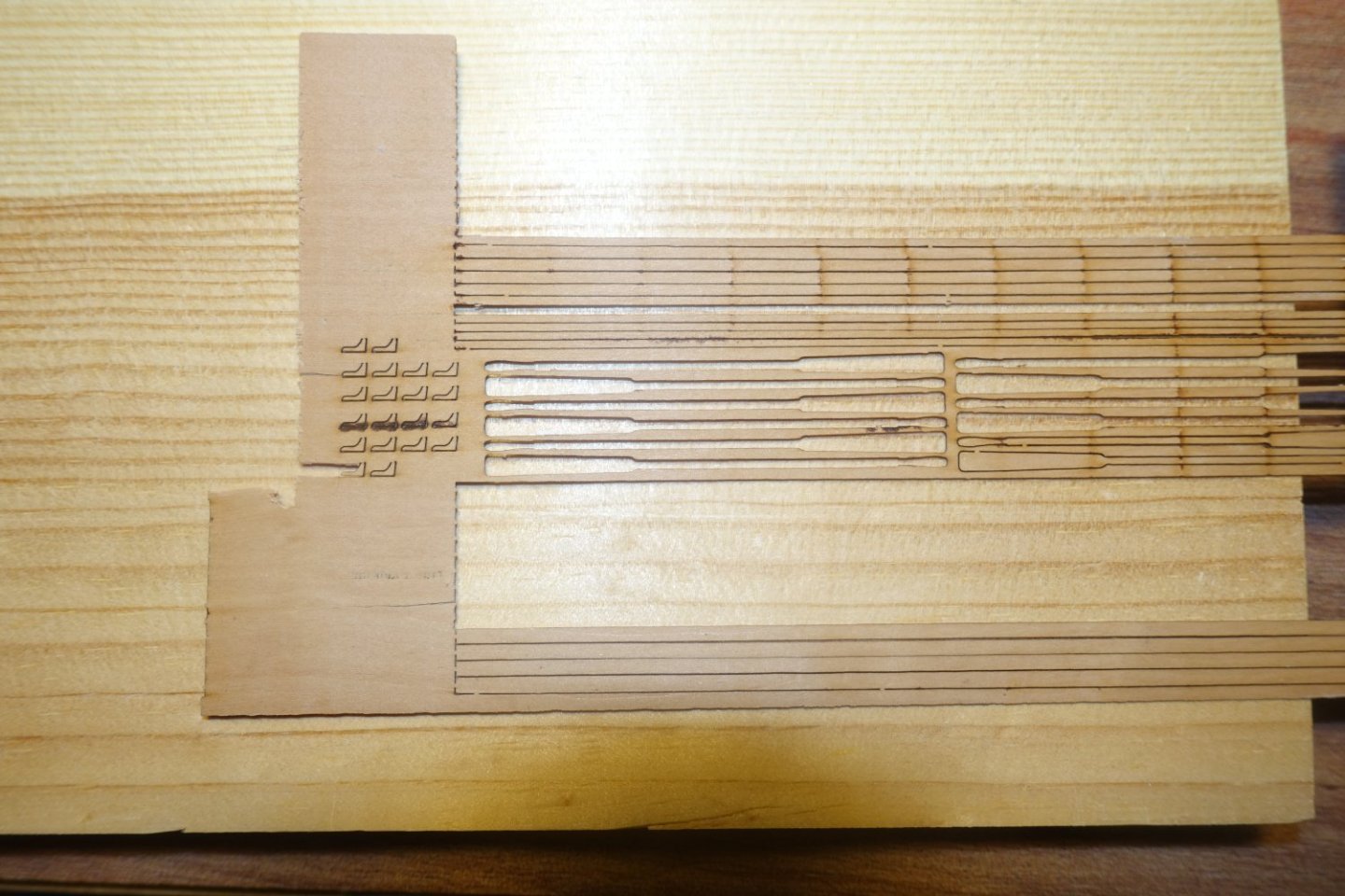
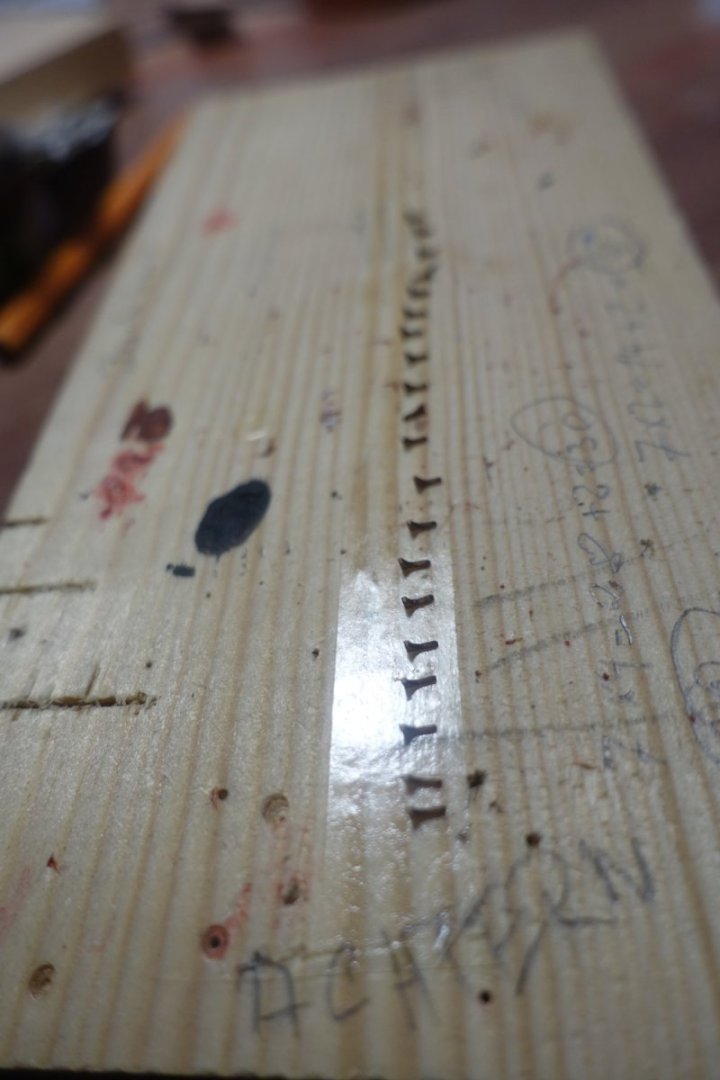
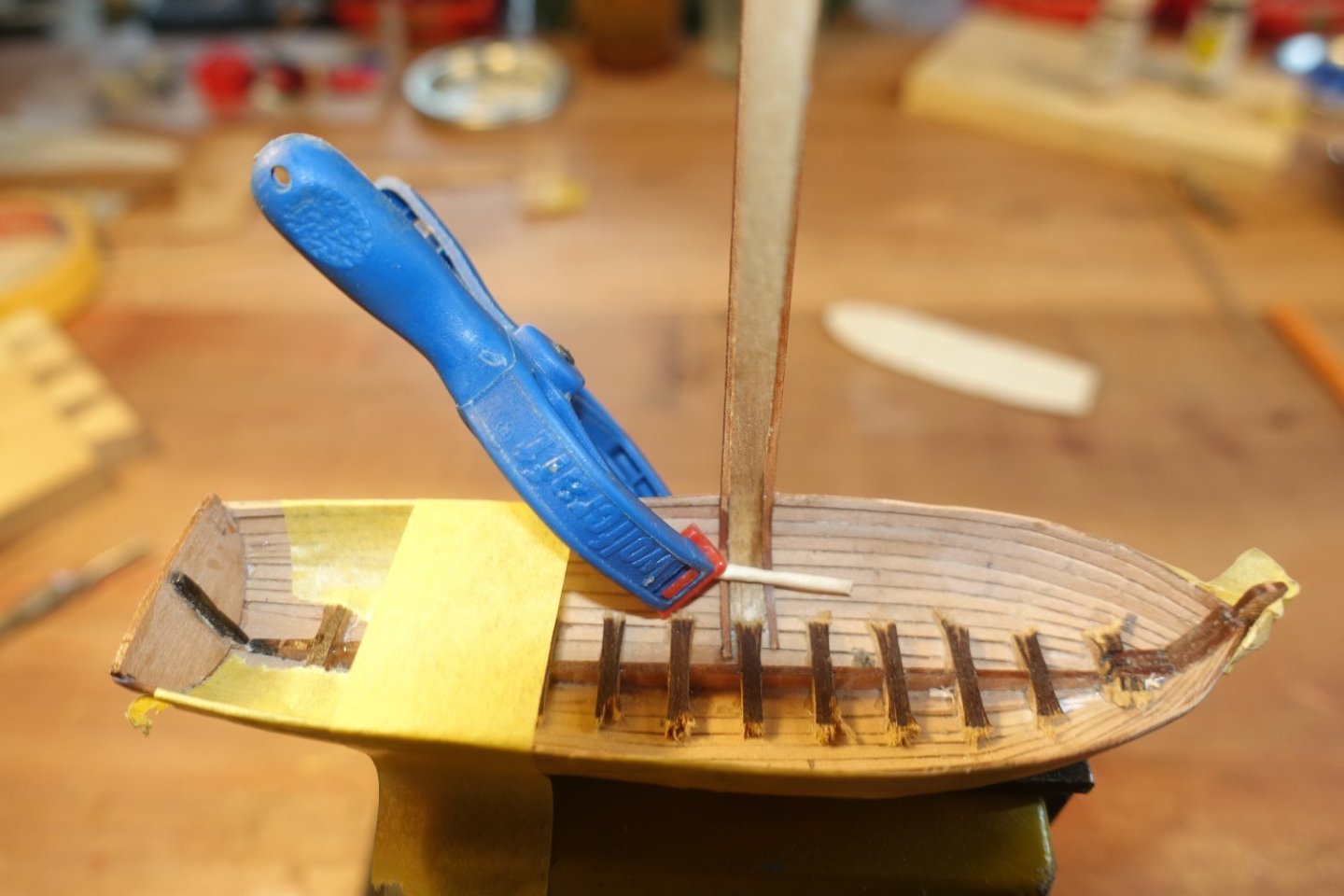
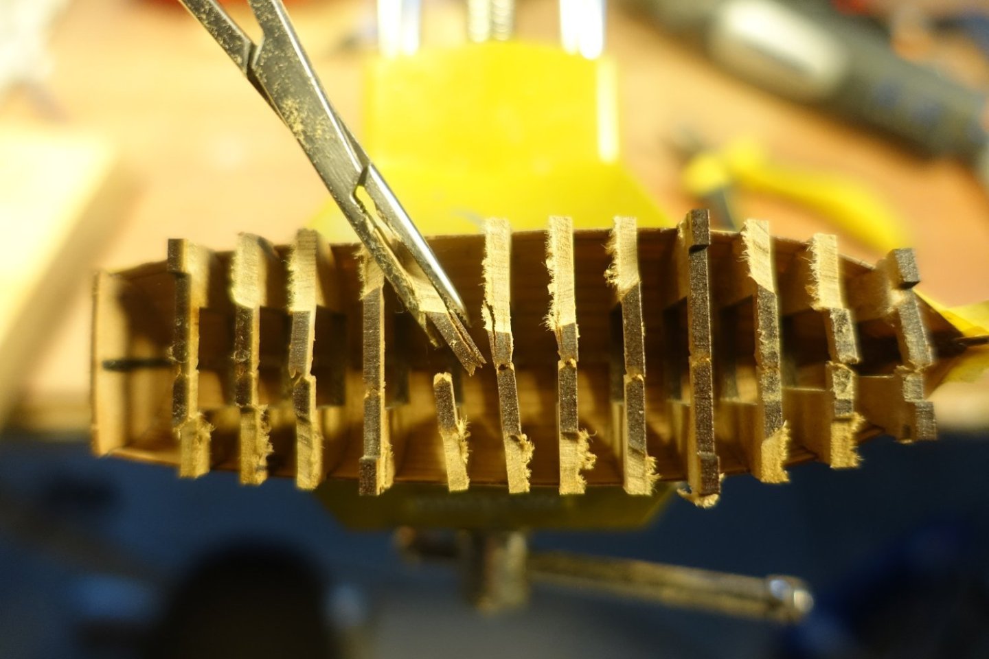
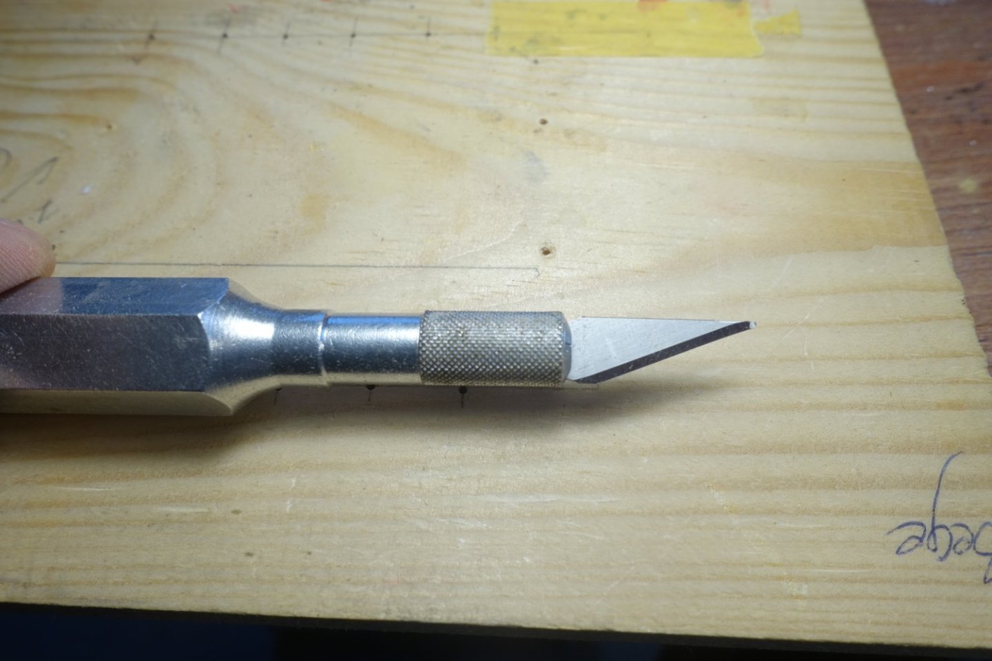
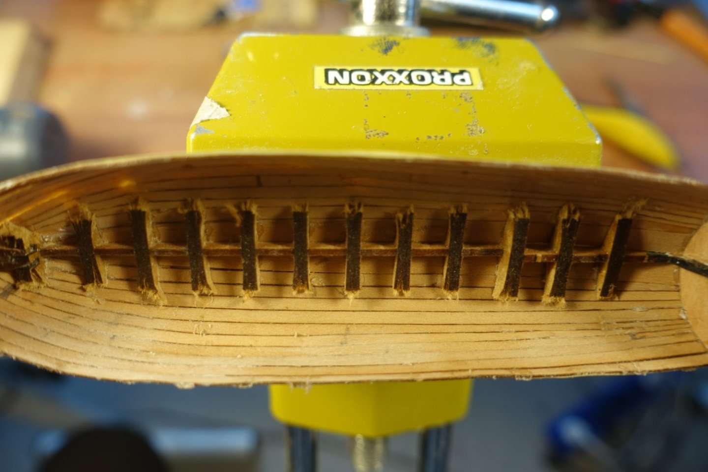
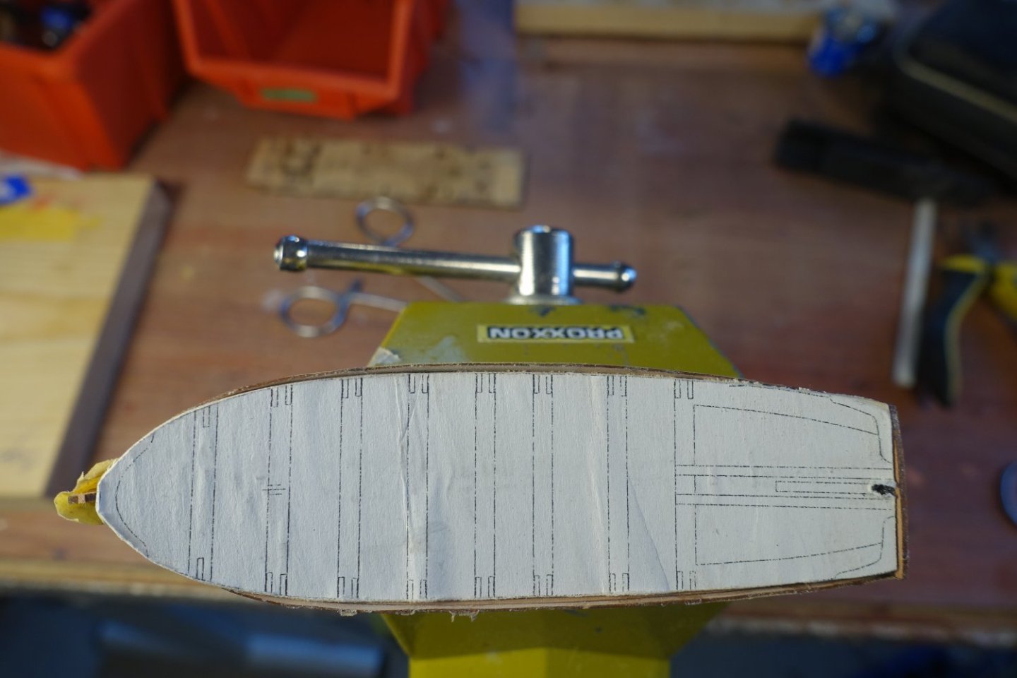
To remove the boat from its base, I first had to saw the frames that I had previously glued into the frame base. After removing the frame base, the upper bars were cut through and then the frames were removed by turning them. As these were not glued to the planks, this was relatively easy. There are very few traces of glueing visible inboard, only my pencil marks, which I forgot to remove before gluing the planks. . To remove the few traces of glue, I ground a mini chisel from a cutting blade (tip flattened and sharpened). When looking at the edge of the hull, a slight indentation is noticeable on the port side at the height of the 4th frame from the rear. The area was slightly moistened and straightened with the help of a clamp. I cut a template (glued on a wood base) from the plan for further processing. This will later be used to place the ribs and the thwarts exactly.


- 20 replies
-
- 8
-
-
- 24 ft Launch
- Vanguard Models
- (and 1 more)
-
Thank you for stopping by. The Portland is certainly an extremely ambitious project that will take the model builders further, also with the markings for the plank width. However, I'm not sure whether this makes sense and works with the small MDF frames of Chris' boats. Clark
- 20 replies
-
- 1
-
-
- 24 ft Launch
- Vanguard Models
- (and 1 more)
-
You've described the construction very well. I think you experience all the ups and downs with the small boats as you do with the larger ships.
-
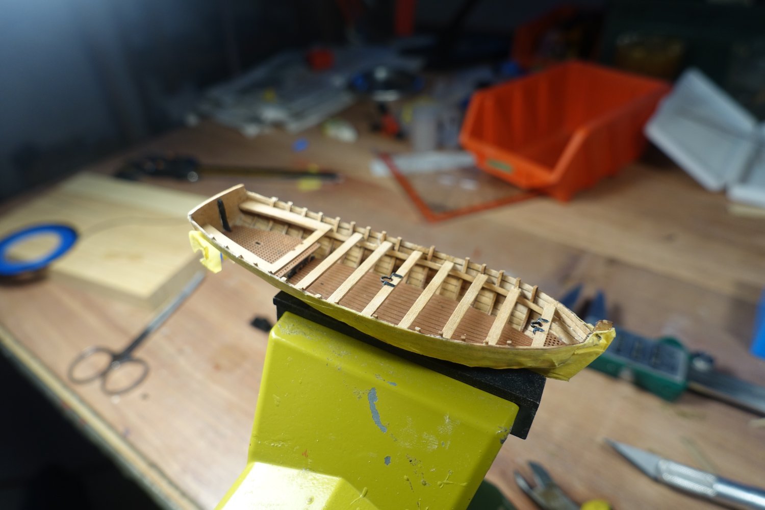
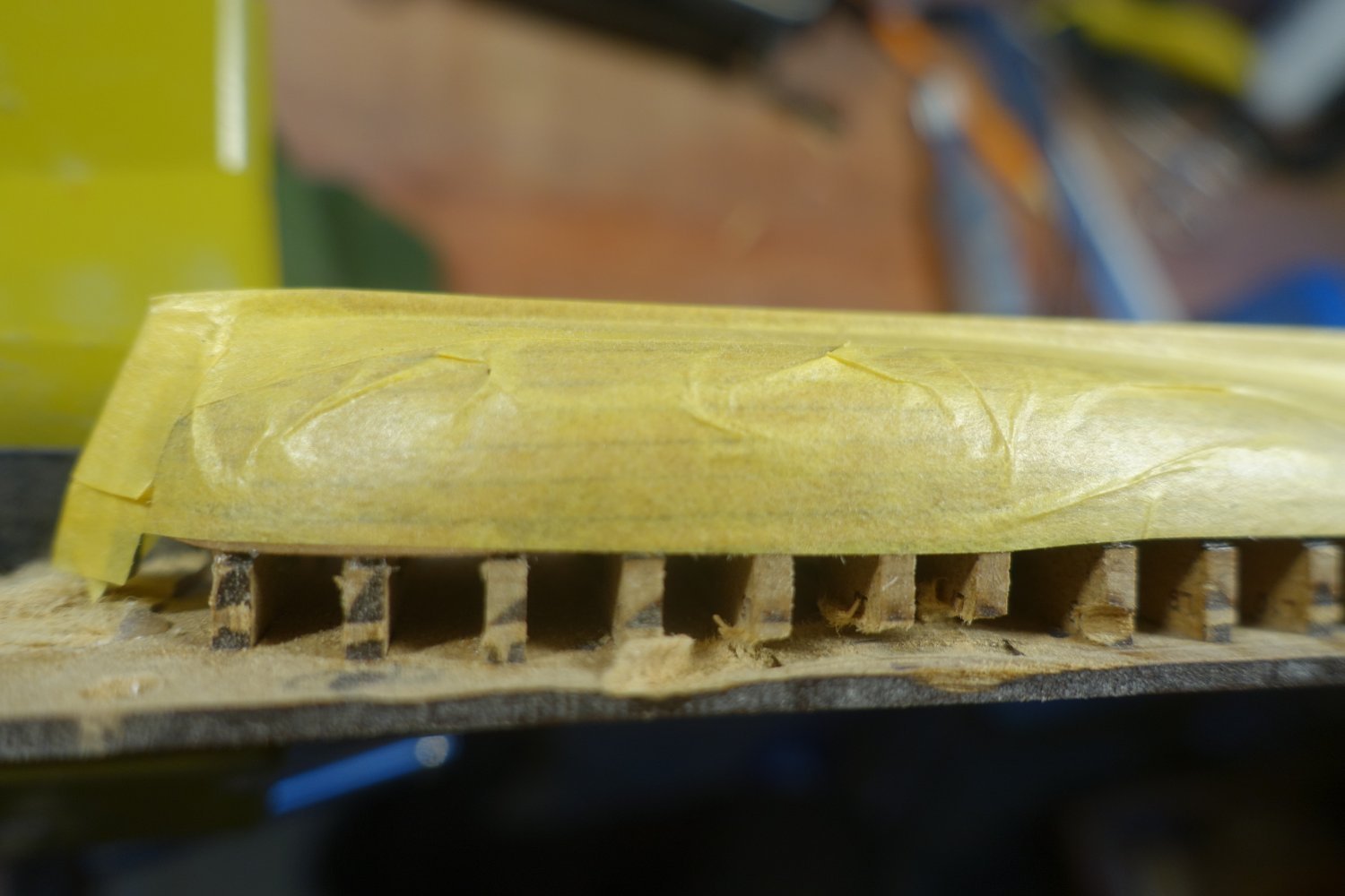
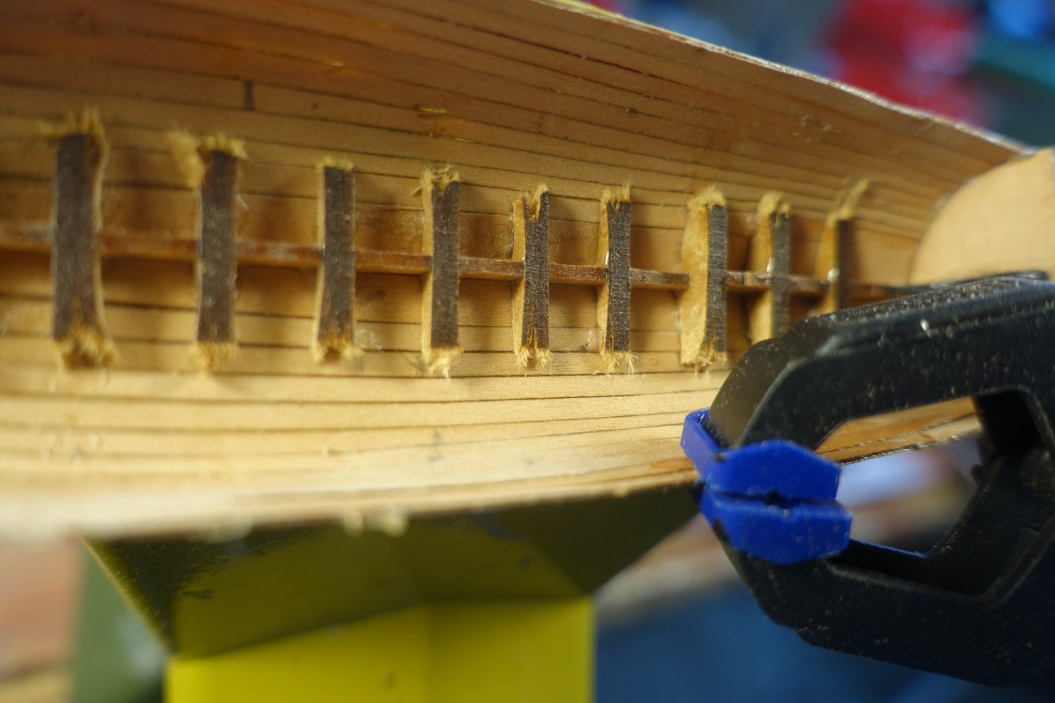
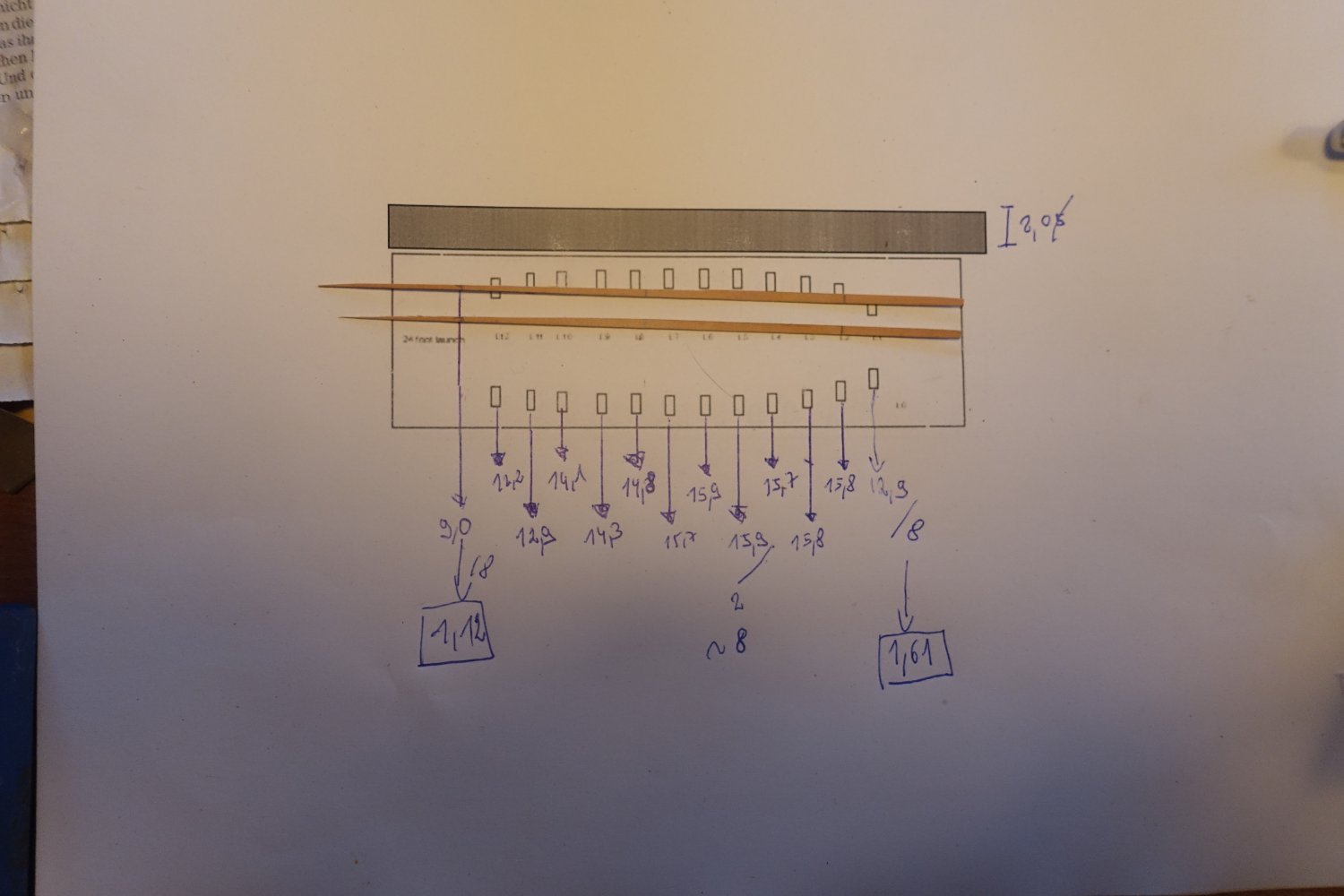
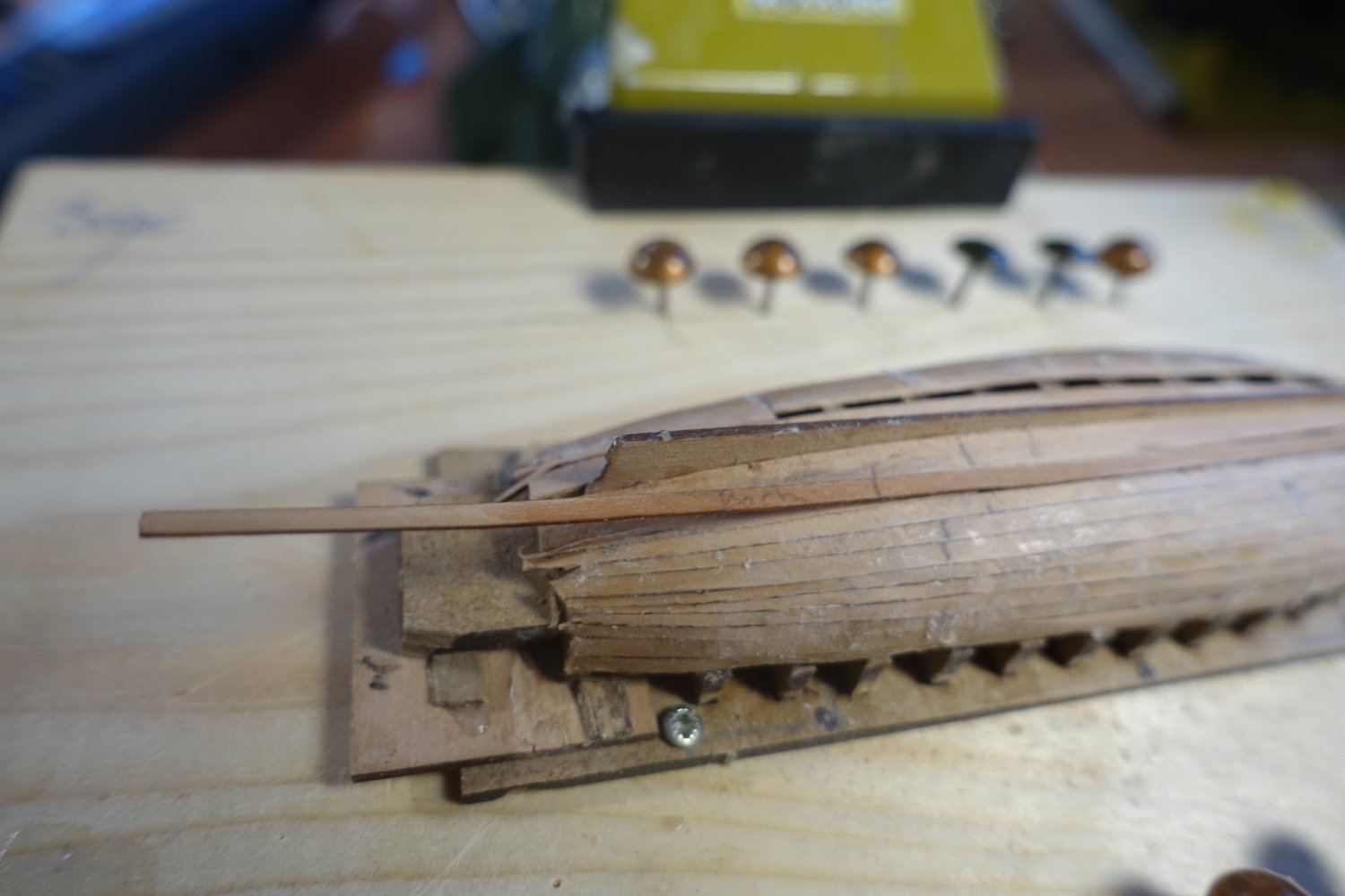
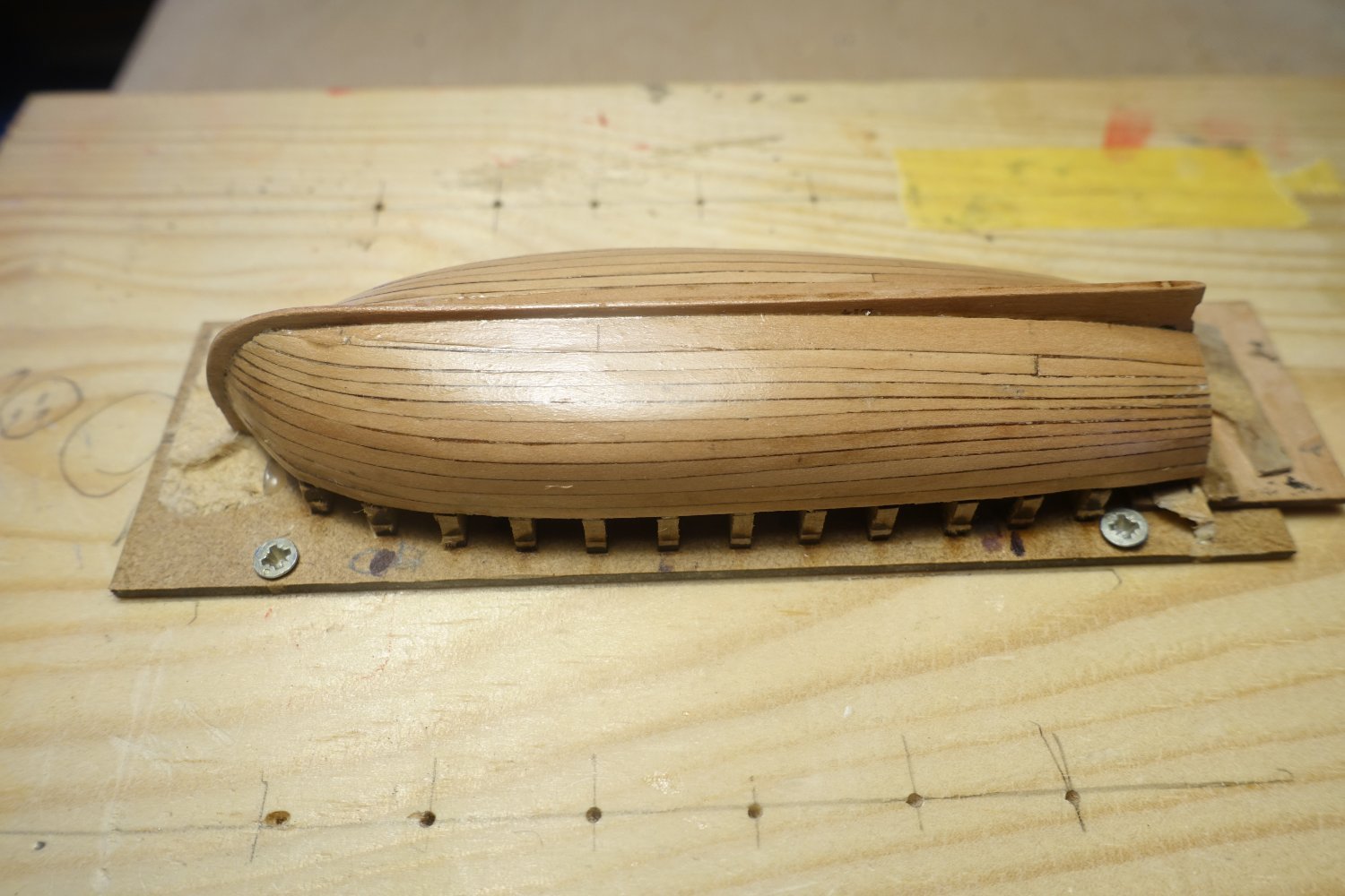
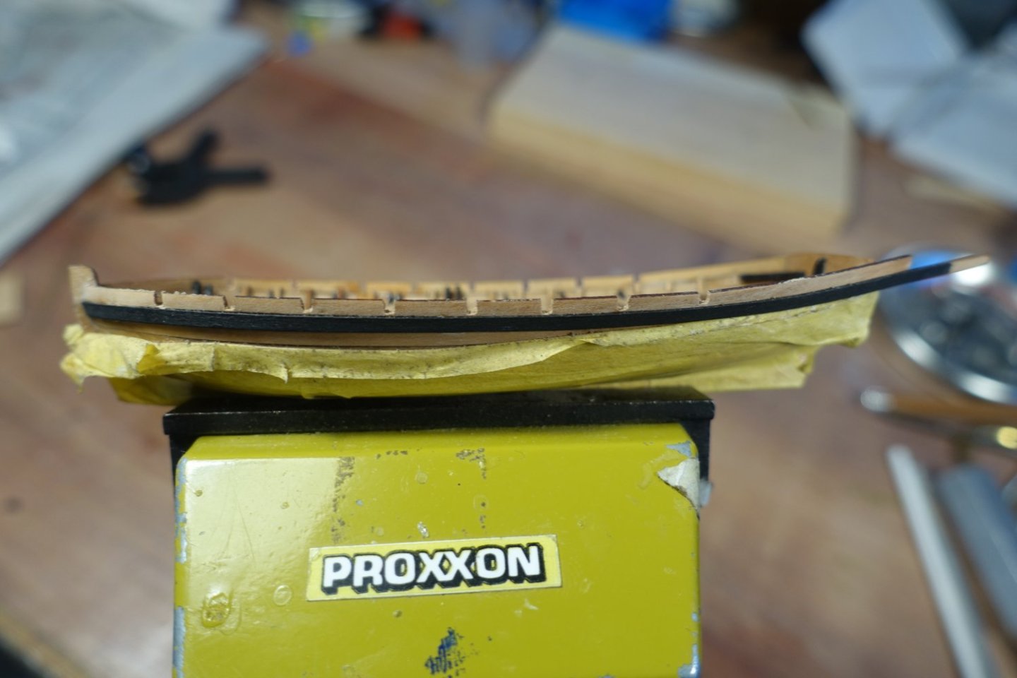
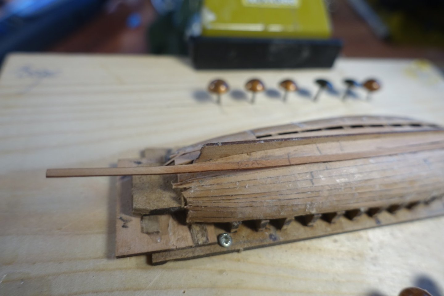
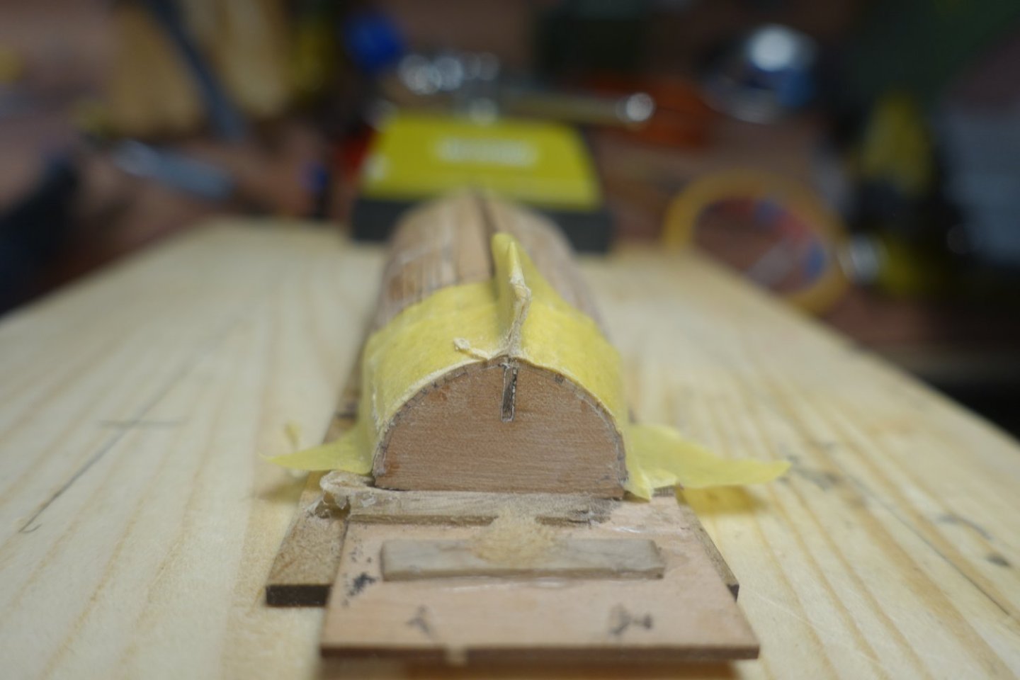
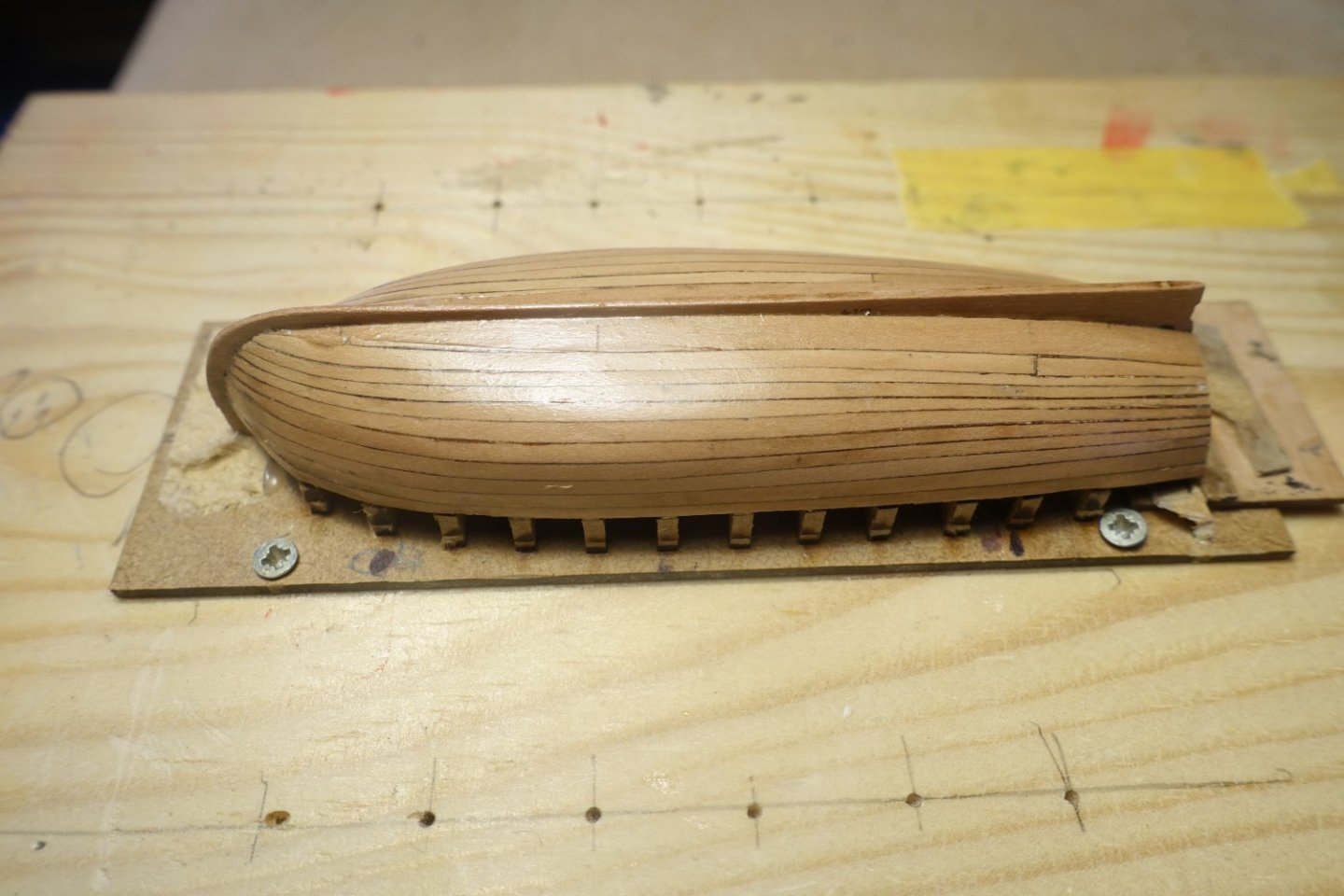
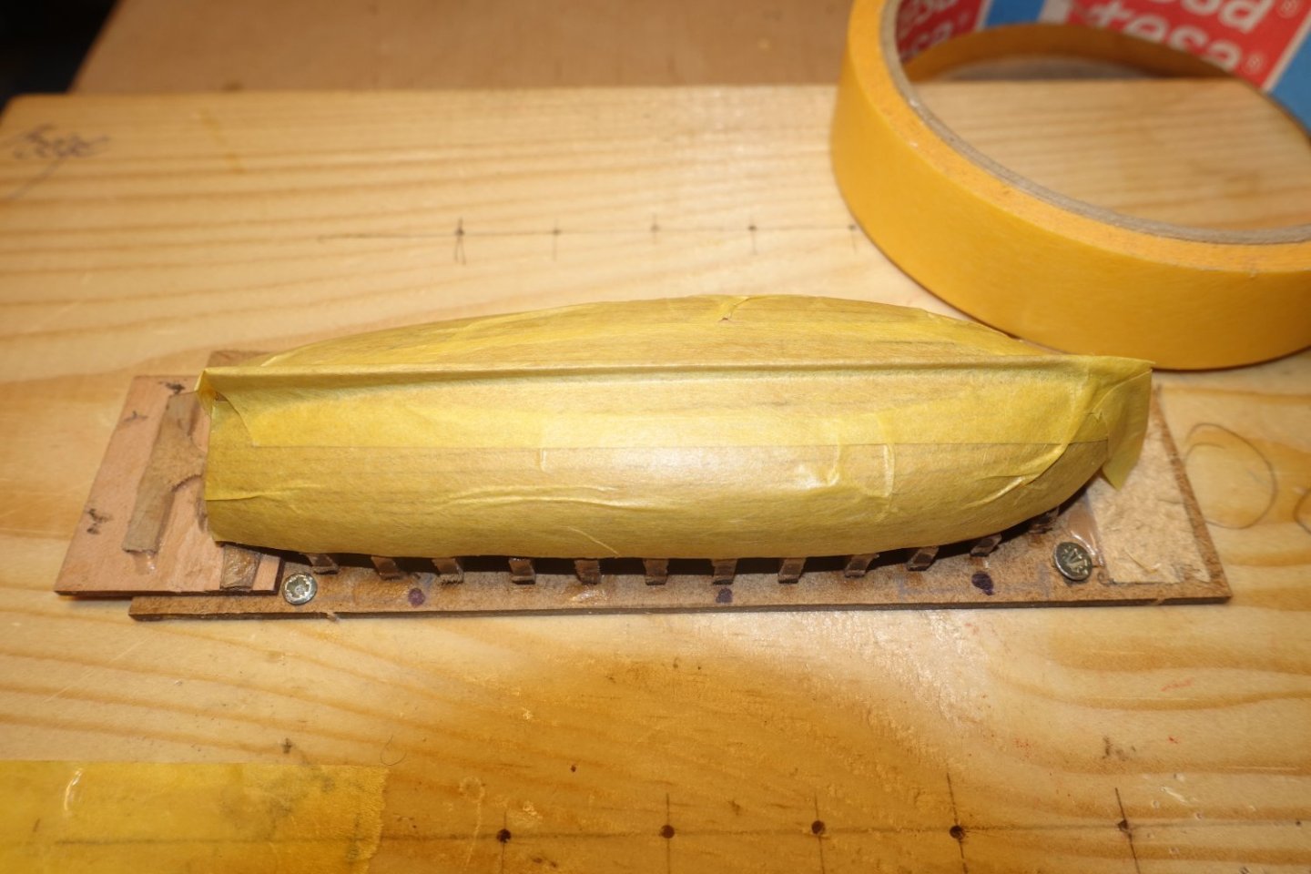
To get a rough idea of the taper still required for the planks, I measured the distance between the garboard strake and the upper planks and transferred it to the plan of the frame board. I then proceeded in the same way as for a larger ship. The largest width in the middle of the hull is 15.9 mm, i.e. with a plank width of 2 mm, 8 planks are required here. Accordingly, a plank width in the area of the first bulkhead of 12.8/8=1.61 mm and a plank width in the area of the transom of 9.0/8=1.12(5) mm. Even if the figures seem accurate, they will certainly have to be adjusted later. In any case, I cut the next two pairs of planks according to these figures. Only the last plank up to the garboard strake is now missing. You could try to take exact measurements of the gap. However, I have found that it is best to adjust by eye. I then adjusted this plank position in two sections (stern and bow). The hull is still littered with white crumbs. These are the remains of the dried PVA glue. It looks bad, but will disappear completely when sanded. Next, I cut off or sanded the protrusions at the stern. To prevent the fine planks from splintering during sanding, I covered them with masking tape. The hull was sanded. I started with 180 grit and finished with 320 grit. I want to present the boat later without paint and also without a waterline, as I always find it nicer when the wood presents itself. I therefore applied three coats of thinned clear varnish. Unfortunately, I missed a pencil mark on the garboard. But I won't sand it all down again, as the line will come to the bottom later and therefore won't be visible. I covered the boat (including stem) with masking tape to prevent bending after removing the frames and to protect the wood. This is the current status of the launch. Furhter posts will follow as soon as a corresponding construction phase is completed.


- 20 replies
-
- 13
-
-

-
- 24 ft Launch
- Vanguard Models
- (and 1 more)