Modeler12
-
Posts
1,716 -
Joined
-
Last visited
Content Type
Profiles
Forums
Gallery
Events
Everything posted by Modeler12
-
 Dave, I don't know but keep a couple things in mind. I am working only with pieces that are six inch long (or 38 feet full scale). Obviously there were a lot of joints that I don't worry about. The width of 9.5 inch is not too bad. And then there is the way I am now approaching my planking. I taper each plank to about the size shown above and then group three of those and edge bond them. Before the edge glue is completely set, I bond them to the frames. I find this work well and gives me better control. I simply clamp the ends and use some tapered nails to force them against the last set of planks. When necessary I use heavy weights in the center to force them against the frames. Hence the drawing of ten planks should now read nine planks (thirteen groups of three plus a single plank to close the final gap).
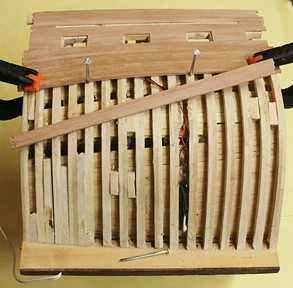
- 572 replies
-
- 5
-

-
- constitution
- frigate
- (and 1 more)
-
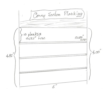
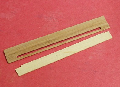
Time to plank the rest of the port side. But before I started that, I connected the wiring for the LED. The picture below shows the location between the frames. It also shows two strips of stiff paper at each end. I will use those to measure and mark the planking widths. Unlike cross sections taken midship, the hull here curves and the planking need to be tapered. Here is how I did the measuring and marking. I measured the length of the two strips of paper and divided the longer one by the width of my planks (0.125 inches). I need 40 planks tapered to 0.121 inch at one end and 0.100 inch at the narrow or forward end. Then I divided the strips into segments of 10 planks each. That will be my guide. After I put on ten tapered planks I will repeat this and recalculate if my planks are going on as planned. What I need to do now is rethink how I am going to taper forty planks.
- 572 replies
-
- 3
-
-
- constitution
- frigate
- (and 1 more)
-
Some criteria for starting a new group project
Modeler12 replied to Chuck's topic in Group Projects on Model Ship World
Chuck, if you can please follow up about the carving thing. I for one would like to join and learn. I think there are enough replies above to get something started, but it would really be good to have one or more person(s) who can 'teach' and/or recommend some literature and tools. I am sure there are individuals here and now who can. -
Me too Mike. This has been going on for at least a year (on and off) and all along I have stalled cutting the opening while being curious - and a bit afraid- to do it Right now, though, I am concentrating on finishing the port side and making sure the wiring will work as I enclose it. Building more planks on the hull will stiffen the whole and make it more stable while cutting those frames for the 'opening'.
- 572 replies
-
- 3
-
-
- constitution
- frigate
- (and 1 more)
-
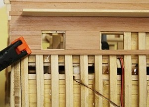
Don't hold your breath about the 'opening'. I decided to tackle the other side first and check out the 'lighting' as well. Notice the wires, one of which goes to the stove. The three LED's and wiring are still working but need to be connected and buried inside the hull. There will be no way to get to them from that point on (without cutting). There will be at least two more that are connected to the back side. The port side planking should be straight forward, but let me make a point about the gun-port openings and their alignment. There should be a small ledge for the gun-port doors to rest on. The pictures below show that the one to the far left needs a bit of 'rework'. All of this is still in a 'dry-lab' situation, so it can be done before I bond the planks in place.
- 572 replies
-
- 7
-
-
- constitution
- frigate
- (and 1 more)
-
This gives me an idea where the side cut-out section will be. Hopefully the pencil marks line up with what I have been saving along the inside. To machine part of the frames away is another challenge. I just want to make sure some of the frames will show. But time will tell. Now that I look at that picture, I am again surprised that the section I chose includes more than I had anticipated. The channel, for example, fits just inside the boundary and that means I can include all of the dead-eyes required for the fore-mast rigging. Next comes the other side and the cut-outs for the canonades. Didn't I say that before?
- 572 replies
-
- 11
-
-
- constitution
- frigate
- (and 1 more)
-
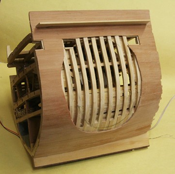
Here is what it looks like now. Obviously this is before bonding them into place. I used a piece of basswood for the inside extension and that will support the inside and outside planking, as well as serve as a edging for the carronade openings. There are still a couple pieces of planking that need to be removed and then I can continue planking the hull down to the wale. Notice that the pencil marks is where the cut-out will happen (if it does ) but I also want to show some of the frames, so the planking goes only part way along the sides.
- 572 replies
-
- 6
-
-
- constitution
- frigate
- (and 1 more)
-
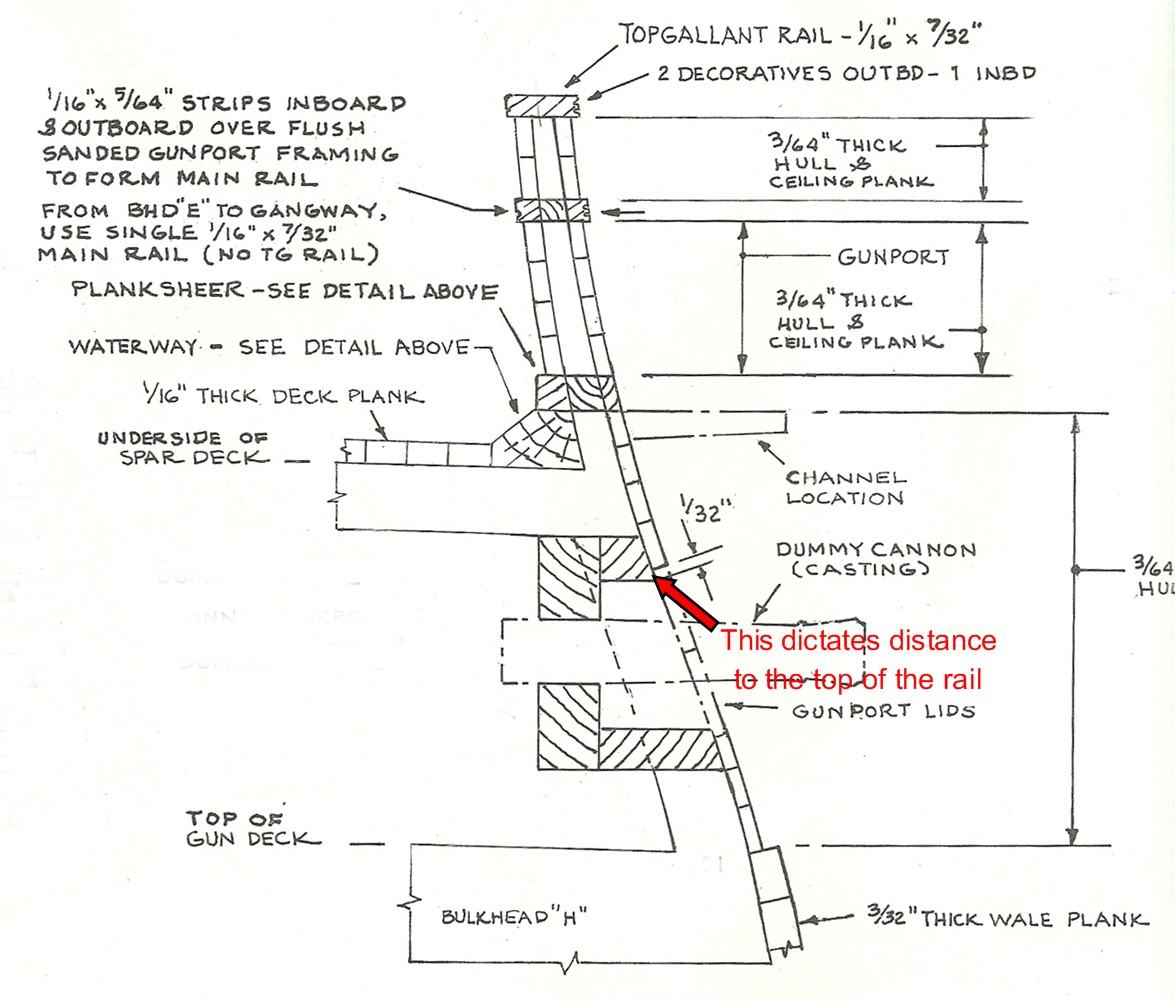
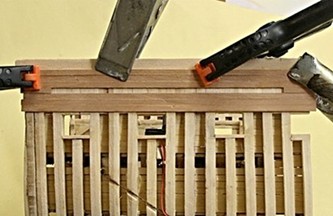
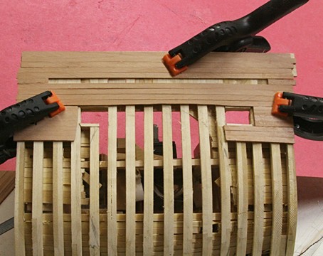
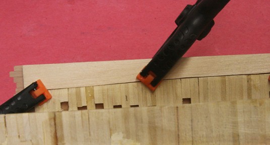
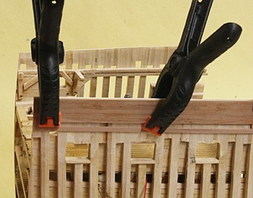
Well, all is not well. My reasoning about the location of the top rail was flawed and I had to tear things apart (the planking I mean, a day-and-a -half of work). All along I have been building this thing from the bottom up (like real ships). But then I decided to go the other way and it went sour. The location of the top rail should be dictated by the distance up from the gun port holes. The drawing below shows this. Hence the hull planks should be aligned using the gun ports as a reference. What happened with mine is that some of the planks had to be cut narrower and at a small angle. Wrong. You can see that in the last picture above, the one of the hull with clamps holding some planks (that are now removed). To meet the gun ports the fill planks had to be cut the wrong way. I am glad I caught this now while the adhesive was semi cured. This drawing also shows the increased thickness of the wale planks. Something I have to remember.

- 572 replies
-
- 11
-
-
- constitution
- frigate
- (and 1 more)
-
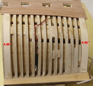
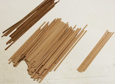
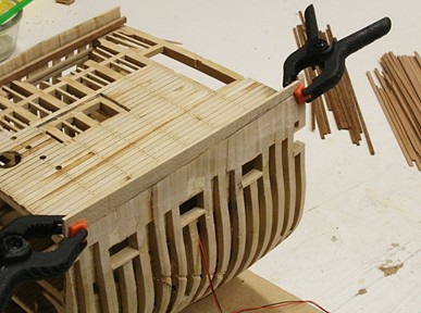
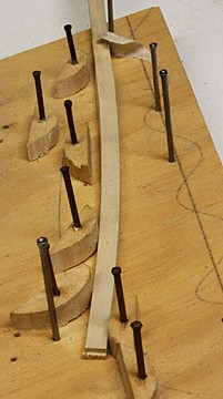
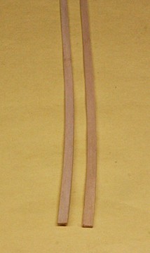
Now that I have the saw the way I want it, it is time to make some saw dust. For the outside planking I am using swiss pear and for the bulwarks (inside top part) it will be mahogany. I'll be using lighter colored wood (such as holly and boxwood) for the fife rails, channel and top rails. That should give it a nice contrast. But first I needed to level the top edges of the framed hull. It took a bit of juggling to arrive at the correct height such that there are five planks above the waterway. Note that the spar deck is still not fixed in place because there is more work to be done on the gun deck, plus the spar deck also needs more sanding and a coat of stain. So I cannot glue the inside planks where they belong. Yet I wanted to have some of the hull planking in place before cutting away the starboard opening. That 'hole' will be just below the channel. I made the channels so that they are embedded between planks. It should be a lot more rigid this way than bonding them simply to the outside. I will not install the channels until much later and probably use epoxy to glue them in place. After these outside planks are glued to the frames, I should be able to locate and cut the openings for the carronades. Finally I cut two strips for the lower 'top-rail'. They are bent to follow the contour of the top edges.
- 572 replies
-
- 11
-
-
- constitution
- frigate
- (and 1 more)
-
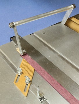
Bill, I might add that the hold down fixture can easily be made using the bracket that came with the saw. It is easy enough to remove the clear plastic saw guard and then put in a bearing in its place. The bearing I used came from one of my router bits. I use this hold-down fixture only for thin boards. It is a bit flimsy for sipping thick stock.
- 11 replies
-
- 3
-
-
- miniature table saw
- Byrnes model machines
- (and 2 more)
-
If you want 'blood red' for the sails, have you considered donating a little for this project?
-
Rigging yards with no sails - question
Modeler12 replied to heksanol's topic in Masting, rigging and sails
In my opinion, if you don't rig the sails don't worry about those blocks and lines that serve only the sail. Namely the sheet lines are gone and so are the leech and reefing lines. Those are now just funny names. However, what is important are the halyards (103) which raises and lowers the spar, the lifts (104) which control the position of the spars up and down as well as the braces (not shown) which position the spars fore and aft. I would add the blocks for 105 and 106 as discussed above, but let them dangle in the breeze. In other words, add the block tied to the spar but don't include a line going through it. BTW learning some of the terminology will help later on during your build. Hence the bold words. -
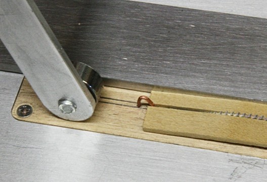
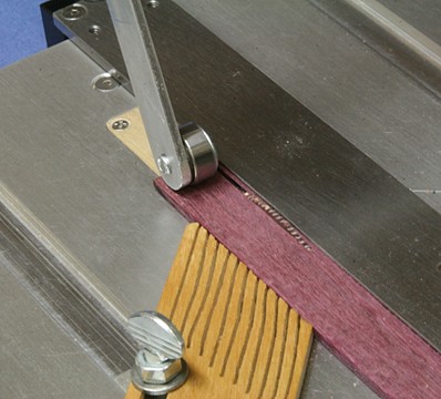
One more addition. A splitter. For my .035 inch thick blade, I used a piece of copper wire at .032 inch thickness. Then I drilled two #66 holes in the zero clearance insert as shown below. I had to make minor adjustments with a pair of pliers and now I am ready to add a couple drops of epoxy underneath to keep the wire in place. The wire does not wrap around the top of the blade, but even so it worked well. The hold-down ball bearing will be moved forward when in use, but for the picture I had it sitting well behind the splitter.

- 11 replies
-
- 8
-
-
- miniature table saw
- Byrnes model machines
- (and 2 more)
-
Can i live without a BYRNES TABLE SAW
Modeler12 replied to shihawk's topic in Modeling tools and Workshop Equipment
. . . . . The advantage is no binding because the blades don't heat up from the sawdust not being able to be carried away in the cutting process. Kurt Like Julie Mo mentioned this could eliminate the problem I have and that is some burning of wood like the purple heart I show below. Any wood that is rich in sap or wax will tend to burn easily. In my case I have not had binding problems, but the cleanliness of the cut is important. Heating of the wood because of the sawdust could very well be the problem. As you can see in the poor picture above (it was cropped too much from the original) there are several places where chips remained between the teeth. This particular blade was not new but cuts fine with boxwood and others. It is 3 inch diameter, 0.035 inch thick with 170 teeth. So, to remove 85 teeth and refile the rest is a lot of work. Someday, when I don't have anything else to do, I may try that. BTW the piece I was cutting was 0.032 inch thick, had uniform thickness but some burn on the sides.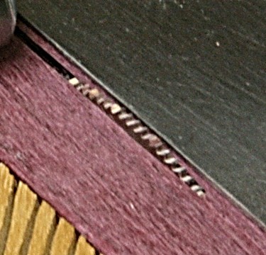
-
Little Machine Shop 2" Quick Vise Review
Modeler12 replied to jhearl's topic in Modeling tools and Workshop Equipment
If I were you, I would call the shop and ask for my money back. I have dealt with Little Machine Shop and found that they are more than cooperative if something is wrong. When I bought their mini mill I also purchased the three inch screw-less vise (#1590) and have had none of the problems you describe. True, mine is a bit tricky to adjust, but once I learned how, it works great. The dove-tail sides prevent the twisting you mentioned. Looking at your pictures, I don't think it is the quality control of the part (ground steel surfaces, etc.) but it is the poor design. -
Here is my second addition. It is essentially a hold down fixture but uses a ball bearing mounted as shown. The design came from seeing what another modeler had done to cut thin veneer. Jim Byrnes also uses this idea for his clear blade guard. I have cut several pieces this way and it really works very well.

- 11 replies
-
- 15
-
-
- miniature table saw
- Byrnes model machines
- (and 2 more)
-
I keep thinking of things to add to my Byrnes table saw. Earlier I added a feathering board and now a hold down clamp. Actually it is a ball bearing pushing down on the work piece. The concept came from looking at what another modeler had done cutting thin veneer. I simply added a ball bearing to that design. Jim Byrnes provided a threaded hole on the far side. He used that to add a clear guard around the blade. It has the same design features that I used here. I have cut a few pieces this way and it works like a charm.

- 572 replies
-
- 6
-
-
- constitution
- frigate
- (and 1 more)
-
Can i live without a BYRNES TABLE SAW
Modeler12 replied to shihawk's topic in Modeling tools and Workshop Equipment
Very impressive Jaka44. The blade Jaka44 shows is made by Schuler http://www.slitting-saw.com/ I have used several different blades made by Thurston http://www.thurstonmfg.com/jewelers-slotting-saws.html I believe Jim uses the Thurston blades that have the 1/2 inch arbor hole and are 3 inches in diameter. They come in several thicknesses ranging from super thin 0.006 inch on up. I typically use #99 at 0.032 inch thickness and 18 teeth per inch. For cutting veneer I go along with Jaka and would use a very thin blade with lots of TPI and I also would reduce the blade diameter to 2.0 inches (#71). I would also minimize the height of the blade above the table. About 1/8 inch would be enough. Perhaps Jim has improved on the fence, because on my saw I don't need to add the ruler. The fence sits very snugly on the table. Correction about the two inch diameter blade. Make that 2.5 inch diameter, because two inches just barely clears the top of the table. Hence Thurston #92 would be better. -
File recommendation please
Modeler12 replied to Sunsanvil's topic in Modeling tools and Workshop Equipment
My soldiers. An accumulation of files I have used over the years. Actually, a couple have never been used they show rust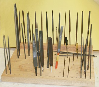
-
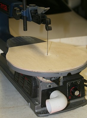
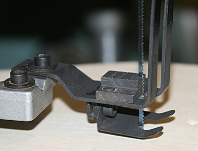
For whatever it is worth, here are two suggestions for making a scroll saw a bit better to control. I bought a used Ryobi scroll saw and added a 1/8 inch thick plywood plate on top of the table. It is held on with double back tape but has a small slot for the blade clearance. It is not exactly 'zero clearance' but darn close. Obviously the foot was removed for this picture. Then I made a couple guide blocks out of oak. The picture below shows the idea. I have found that this gives me very good control when cutting curved pieces and practically no tear out on the back side. I might add that when the oak block wears out (or I have to use a narrower blade) I loosen the screw that holds the block to the foot, and resurface the face. Thus far I have not had to replace the block since it only 'guides' and no heavy rubbing takes place, unless I go into tight bends.
-
Can i live without a BYRNES TABLE SAW
Modeler12 replied to shihawk's topic in Modeling tools and Workshop Equipment
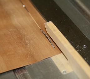
I have cut veneer many times and found that a band-saw or jig-saw are the worst means of cutting an accurate piece without tearing the edges. It requires a very fine tooth such as a 'metal blade' and a zero clearance table insert. To have to change the blade and insert is for me too much of a hassle. A razor blade, scalpel or exacto knife with a good straightedge is much simpler. For curved pieces you could make a template if there are enough pieces involved. Julie Mo asked how the Byrnes TS works and I think it is fine for cutting multiple strips of veneer that are narrow. -
Can i live without a BYRNES TABLE SAW
Modeler12 replied to shihawk's topic in Modeling tools and Workshop Equipment
You asked and I tried it. The piece I used was not really warped but it was definitely not flat. I simply cut it on the saw holding it down with a push stick as I fed it with my left hand. It worked but could probably work better if I used a piece of thin stock on top of the veneer to hold it down on the table. I am sure it also depends on how long and narrow you want to cut it.
-
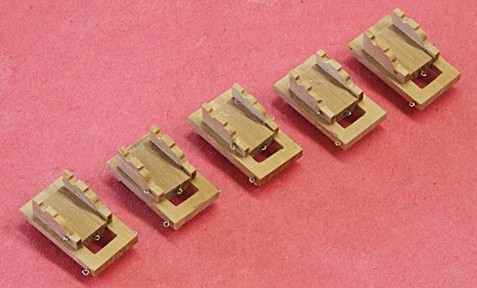
Back to the carronade carriages. Here are five (I need four, so one is in reserve). These pieces were made out of Swiss pear. I have also put hooks on the single and double blocks for the tackles. Obviously there are some parts still missing
- 572 replies
-
- 10
-
-
- constitution
- frigate
- (and 1 more)
-
Tools and Supplies for My "Shipyard"
Modeler12 replied to daveward's topic in Modeling tools and Workshop Equipment
I have not done the search about Bondo on this web site, but there is a good description about its use elsewhere ; http://forum.woodenboat.com/showthread.php?95312-Big-Bad-Bondo I used it on my Conny prior to painting the hull black. It went on well, sanded just perfect and gave me a good finial finish. The paint is still there and holding well . . . But to be sure, I have not used it on tiny pieces, instead I use other compounds . . . .