RMC
-
Posts
933 -
Joined
-
Last visited
Content Type
Profiles
Forums
Gallery
Events
Everything posted by RMC
-
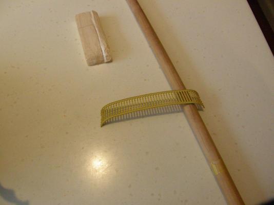
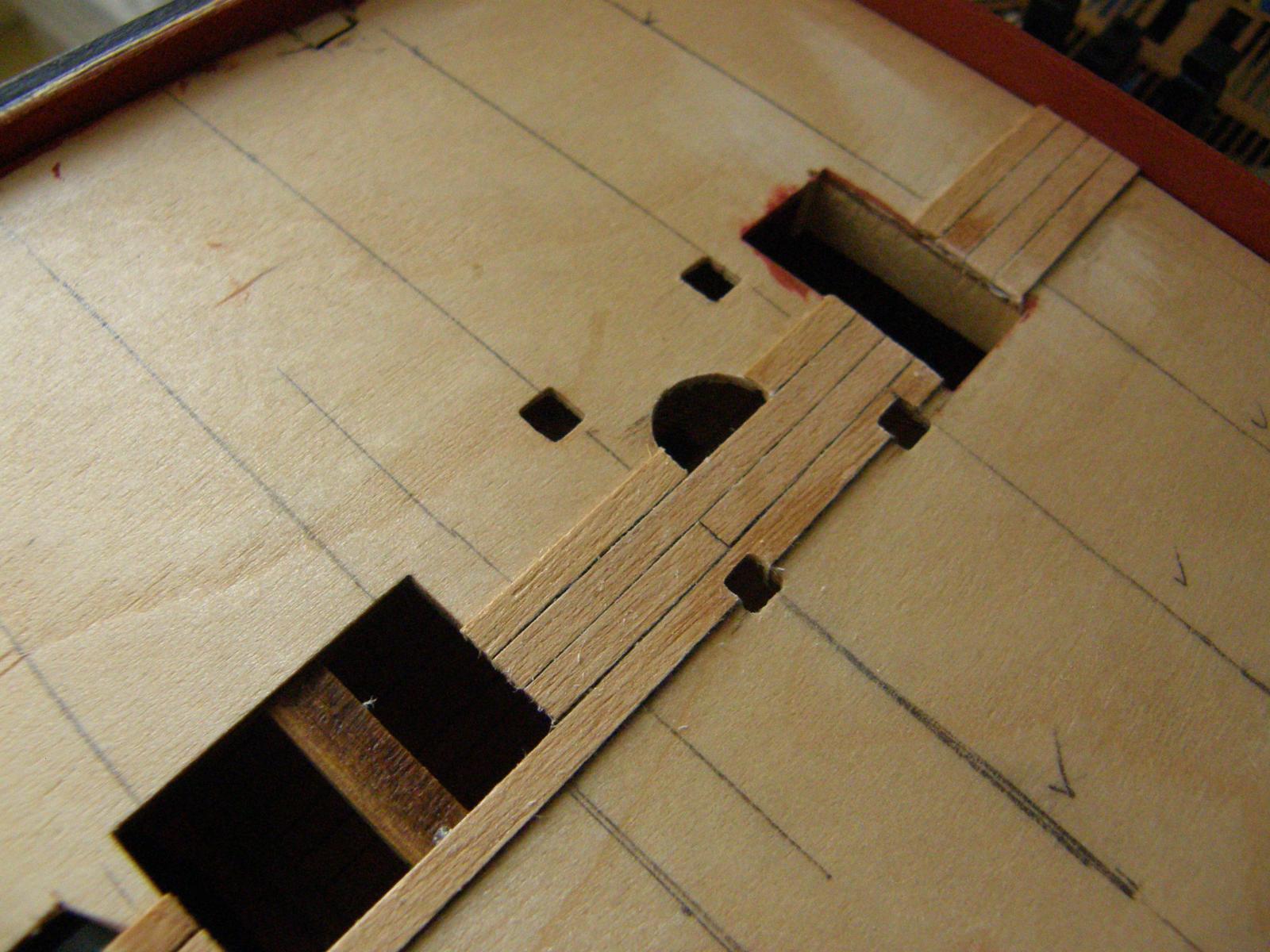
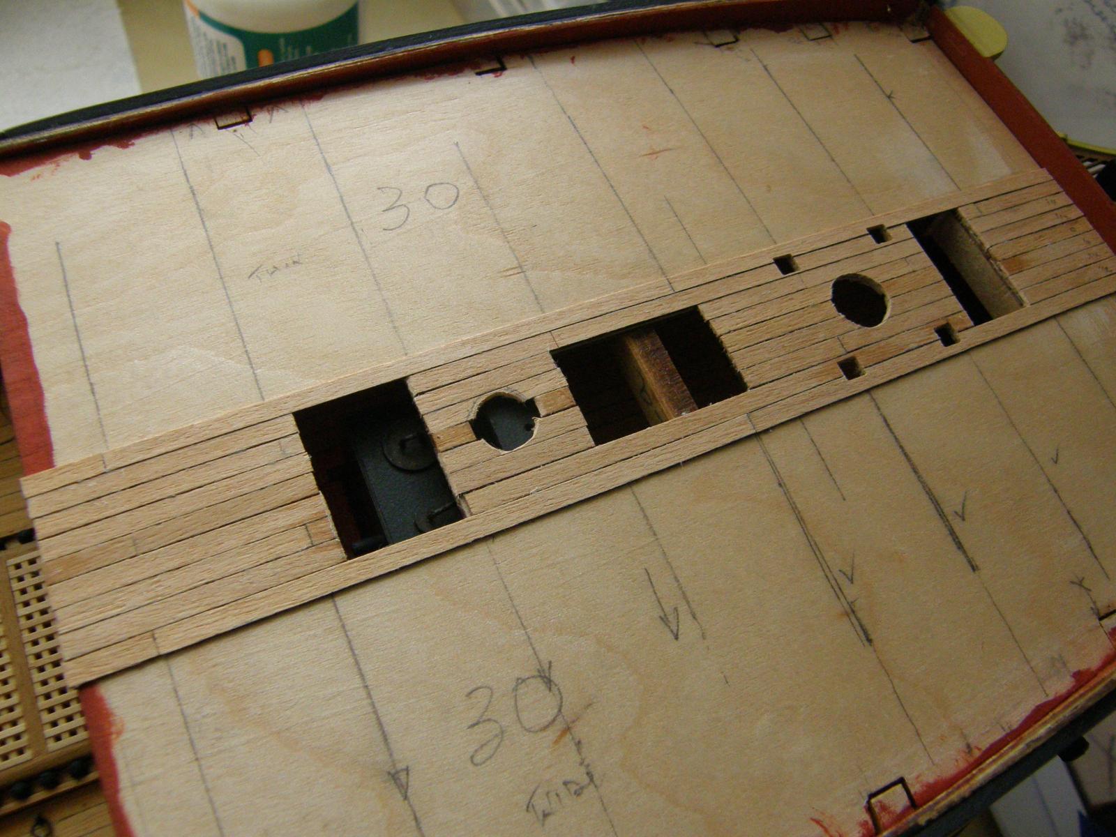
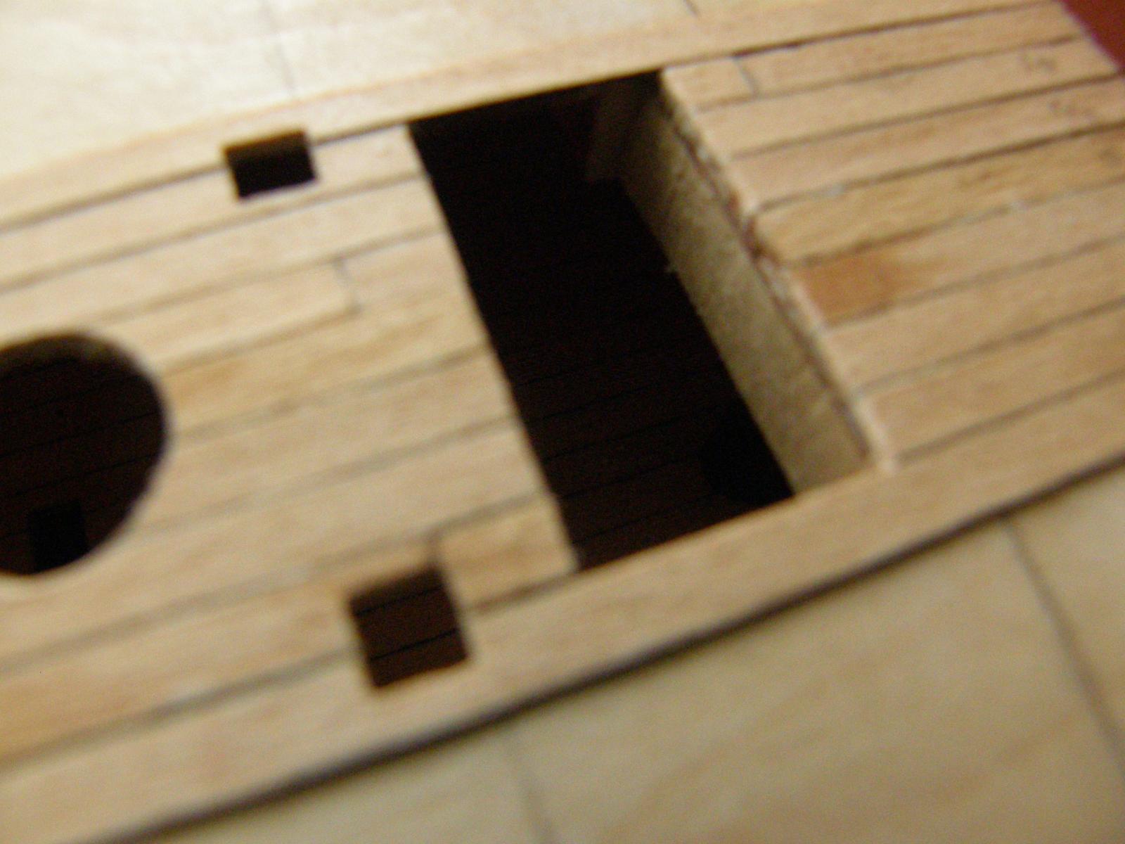
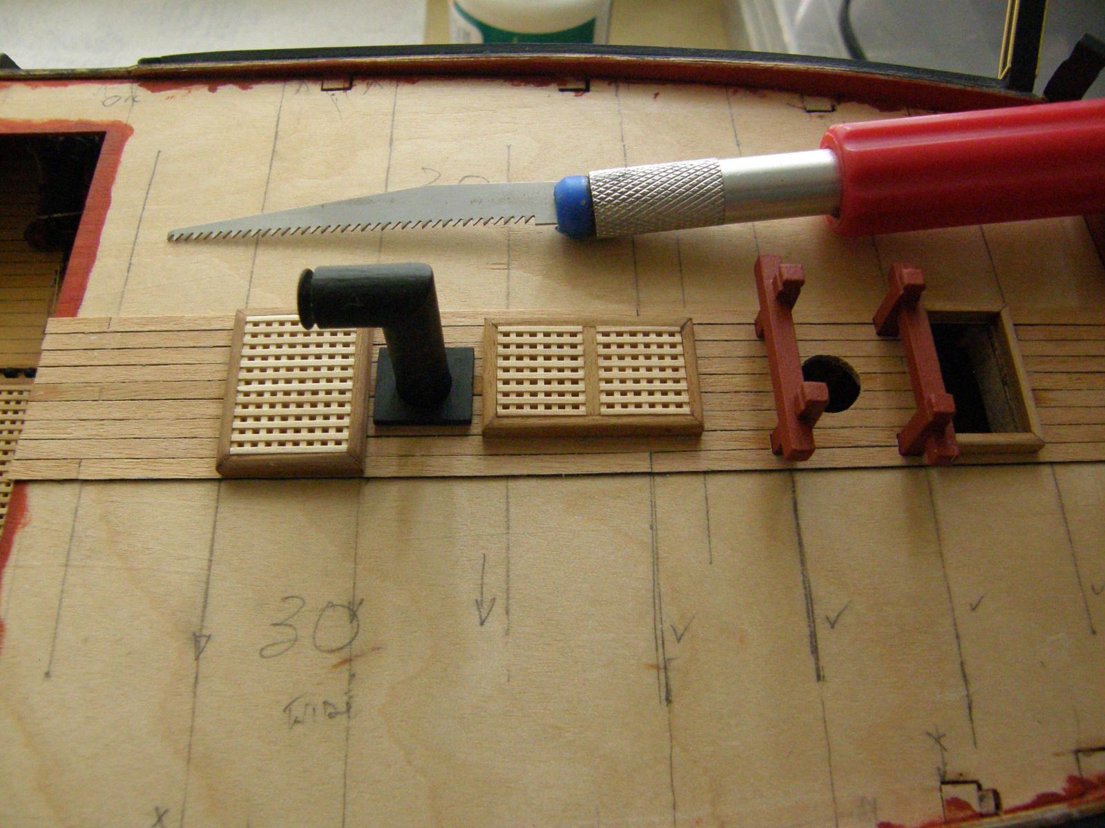
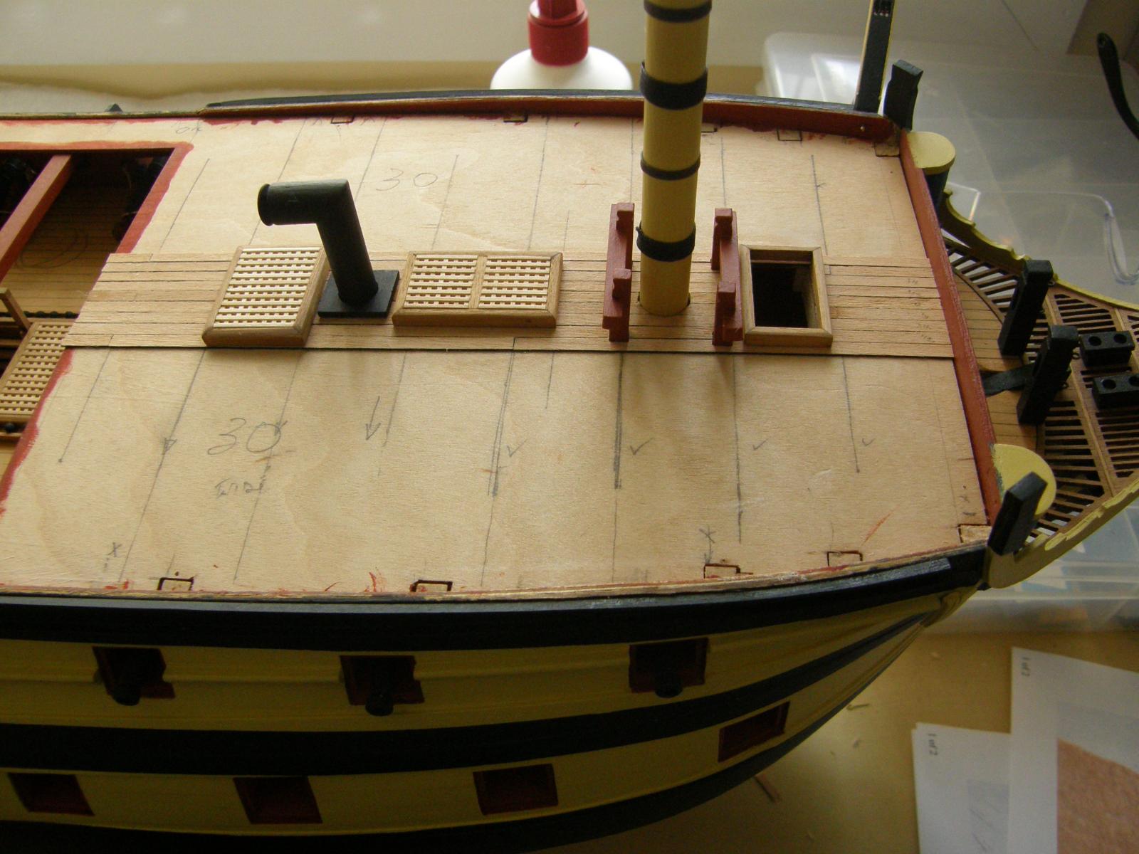
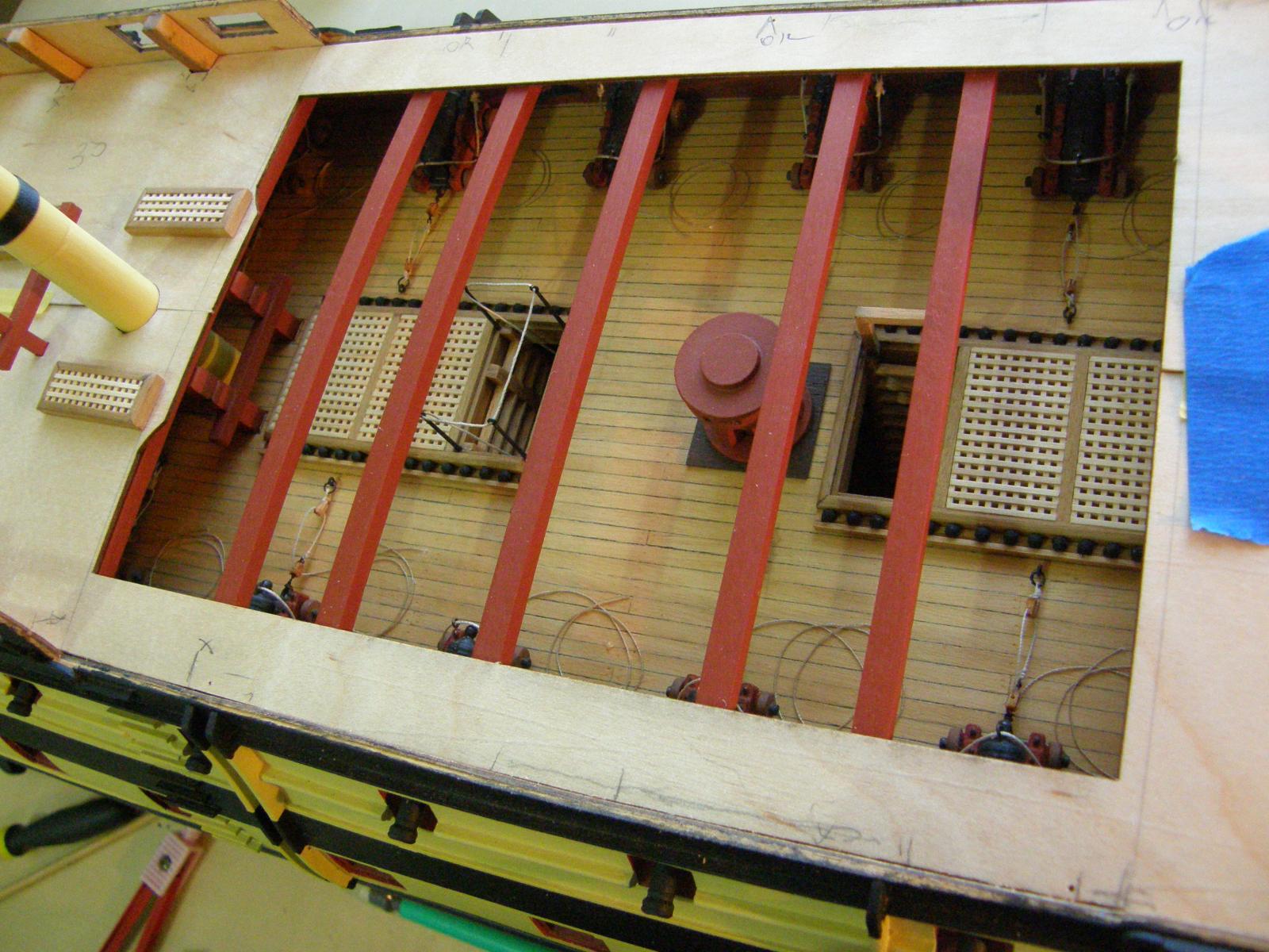
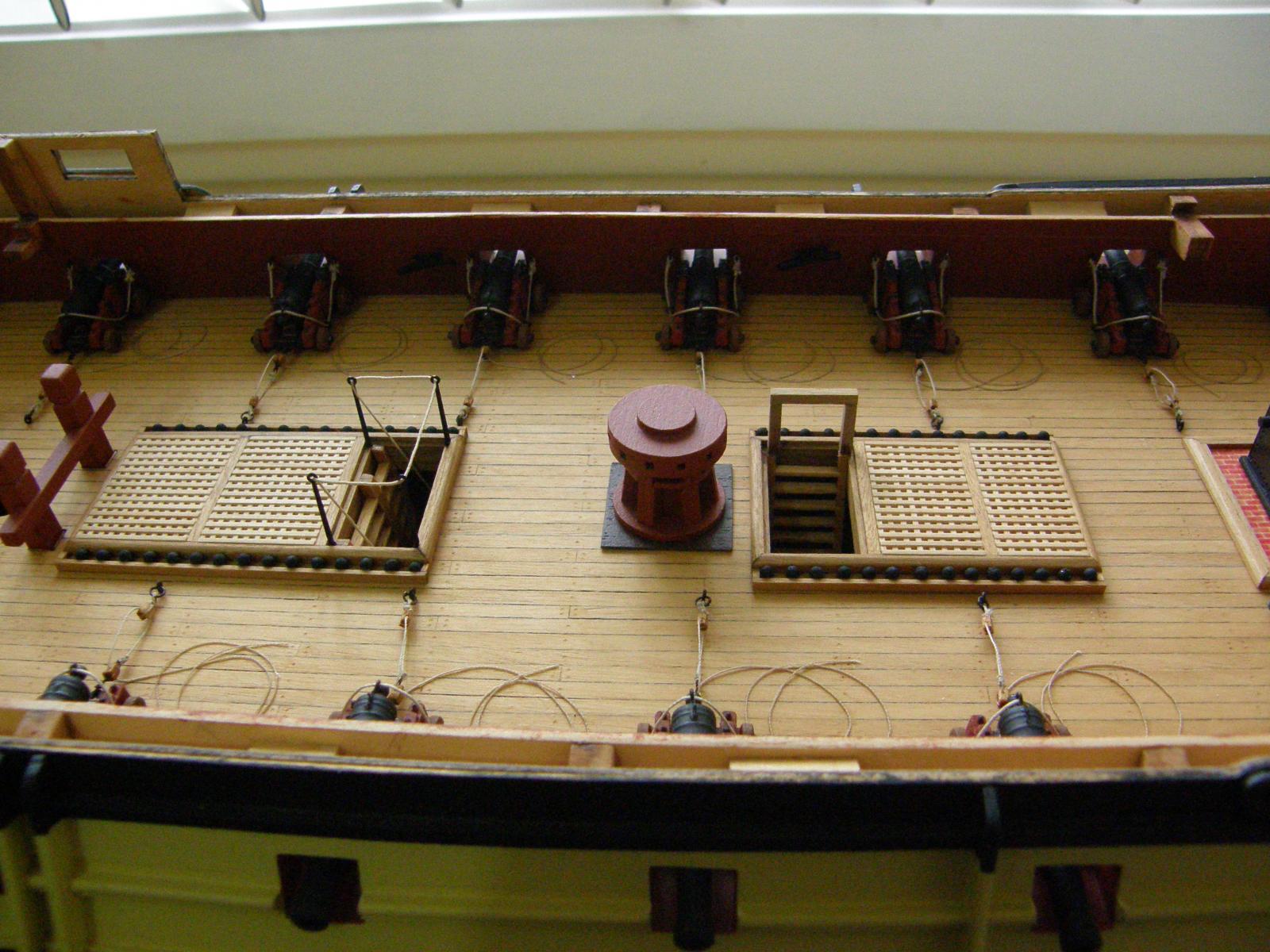
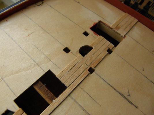
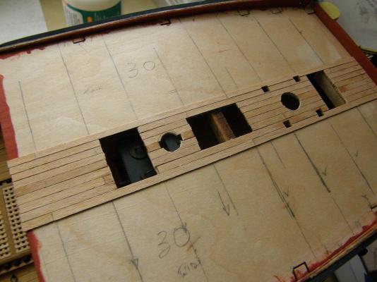
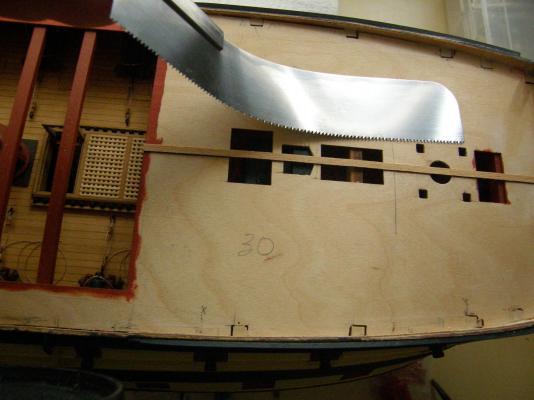
The deck planking has begun. I decided to follow Arthur's lead in cutting a rebate in the deck support under the forward hatch so that stairs could be fitted. It turned out to be not as difficult as I expected, though I was rather nervous while in the process. Cutting the planking to provide for the other deck fittings also went well. I used PVA wood glue applied in a hypodermic syringe. It allows accurate application of the glue and minimises wastage. These show the rebate cut in the first deck support. The deck furniture dry-fitted. Here is the saw used in cutting the rebate. The blade is alarmingly sharp. I first drilled a number of holes about the middle of the support to provide access for the saw and then sawed away. The result is a nice clean cut.


-
Thanks for that. The saw came from hobbytools.com.au I think there is enough of the support left if I cut a rebate. It's a pity not to have had more foresight. I'll have a look tomorrow morning
-
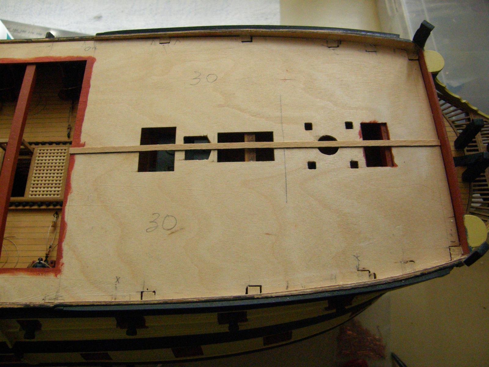
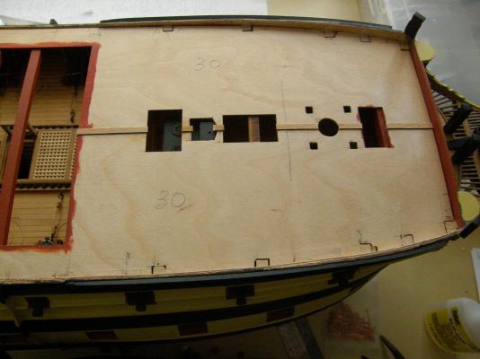
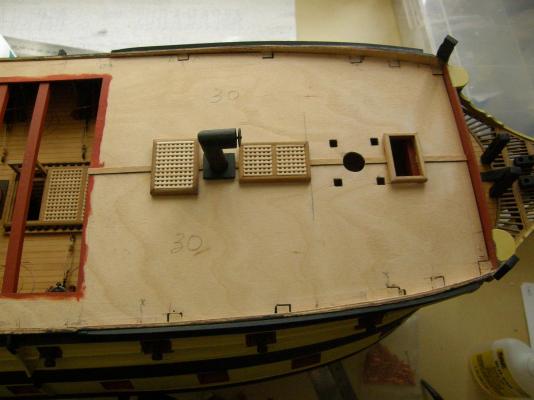
The 'lid' has finally been put on the gundeck.
-
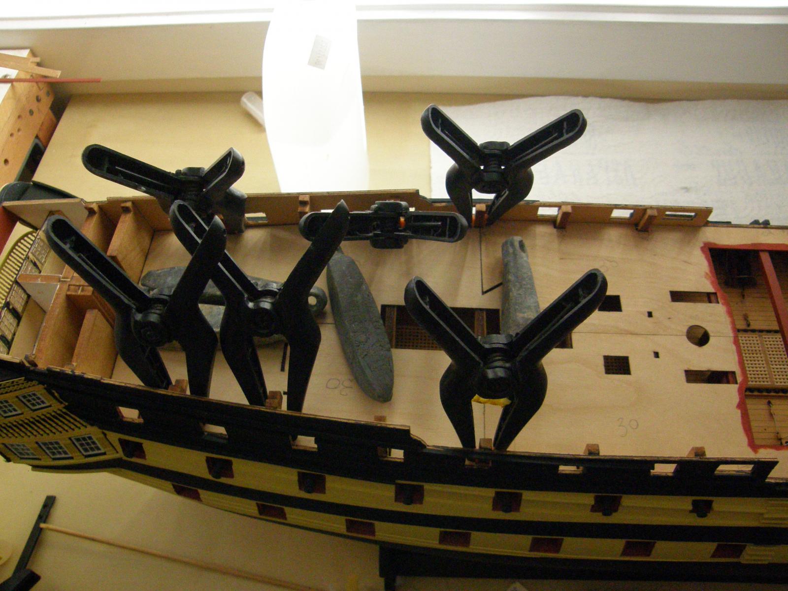
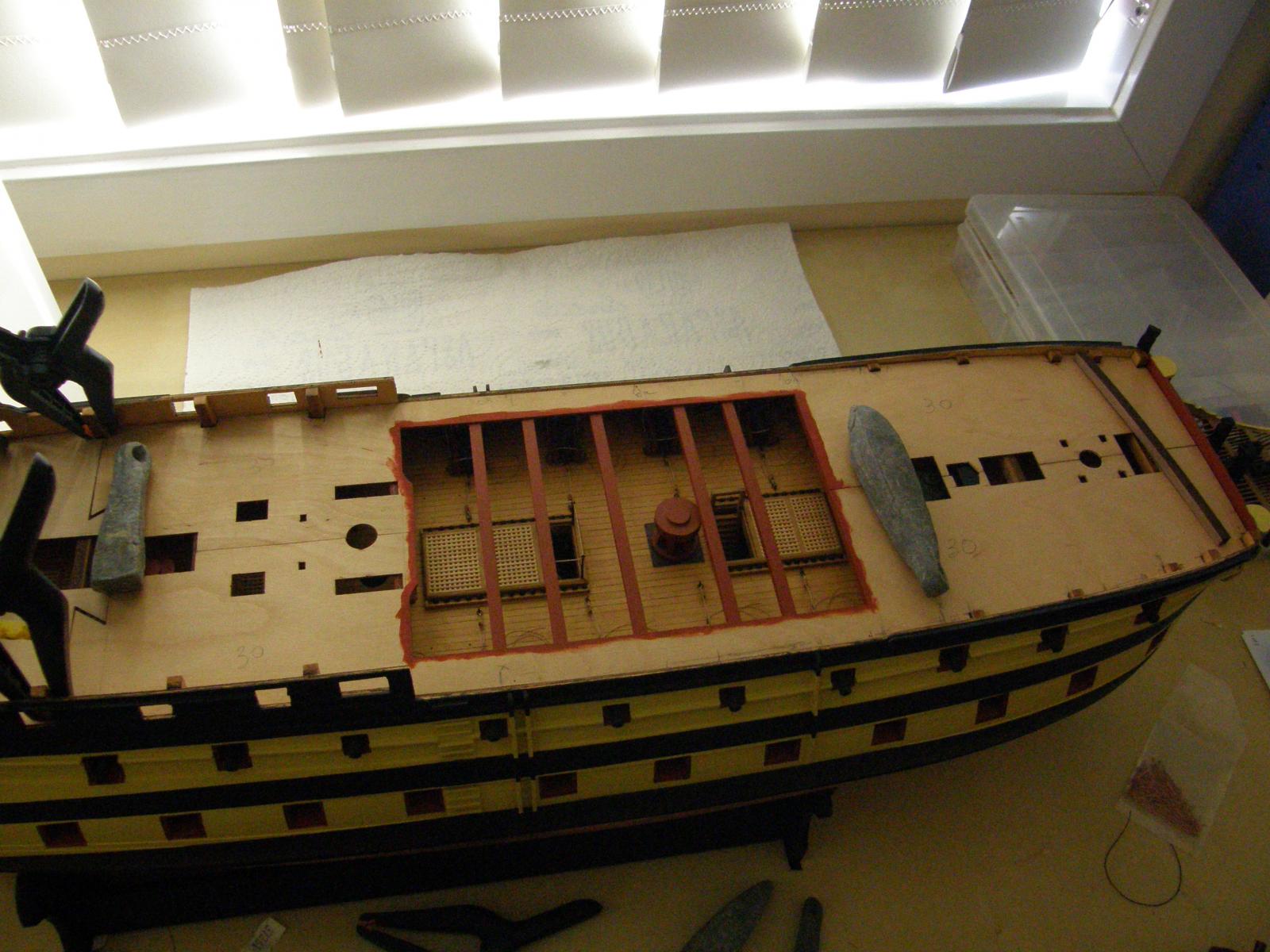
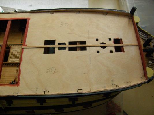
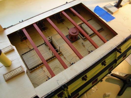
I have finally added the 'lid' to the gundeck. I have finally found a useful use for sinkers. They certainly haven't been very useful for fishing lately. I have applied a plank all the way down the centre of the deck and will use it as the base for spacing the remaining planks towards the edges. I bought a rather amazingly flexible saw to cut off the deck supports flush. It worked a treat. The deck fittings are test fitted. There is a support almost directly under the forward hatch. A ladder is supposed to be fitted into it. It's really not possible without cutting the support - which does not seem to me to be an especially good idea. I'll probably leave as is unless someone can suggest something better.


-
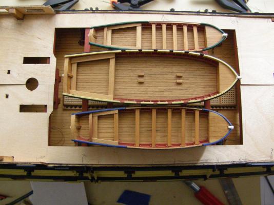
Thanks Arthur I remembered from your log the that the position of largest boat is offset and I spent some time this afternoon going through it. I'm glad you too couldn't make out just what the shapes of the cradles may be. The ones towards the stern of each boat don't seem to bear any resemblance to the shapes of the boats.
-
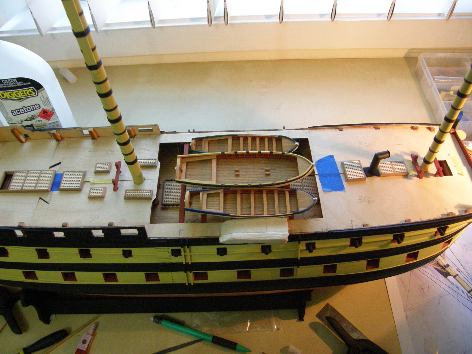
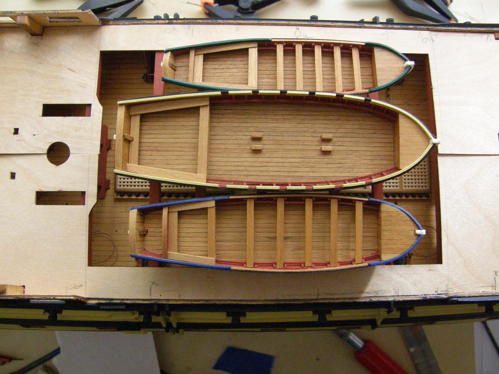
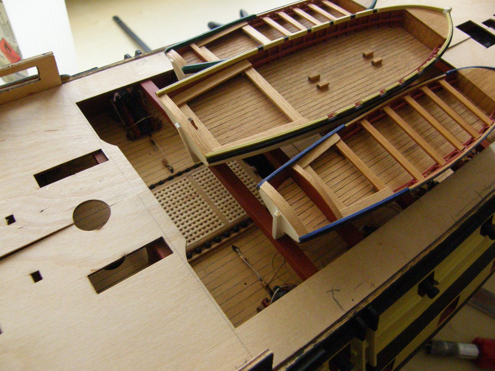
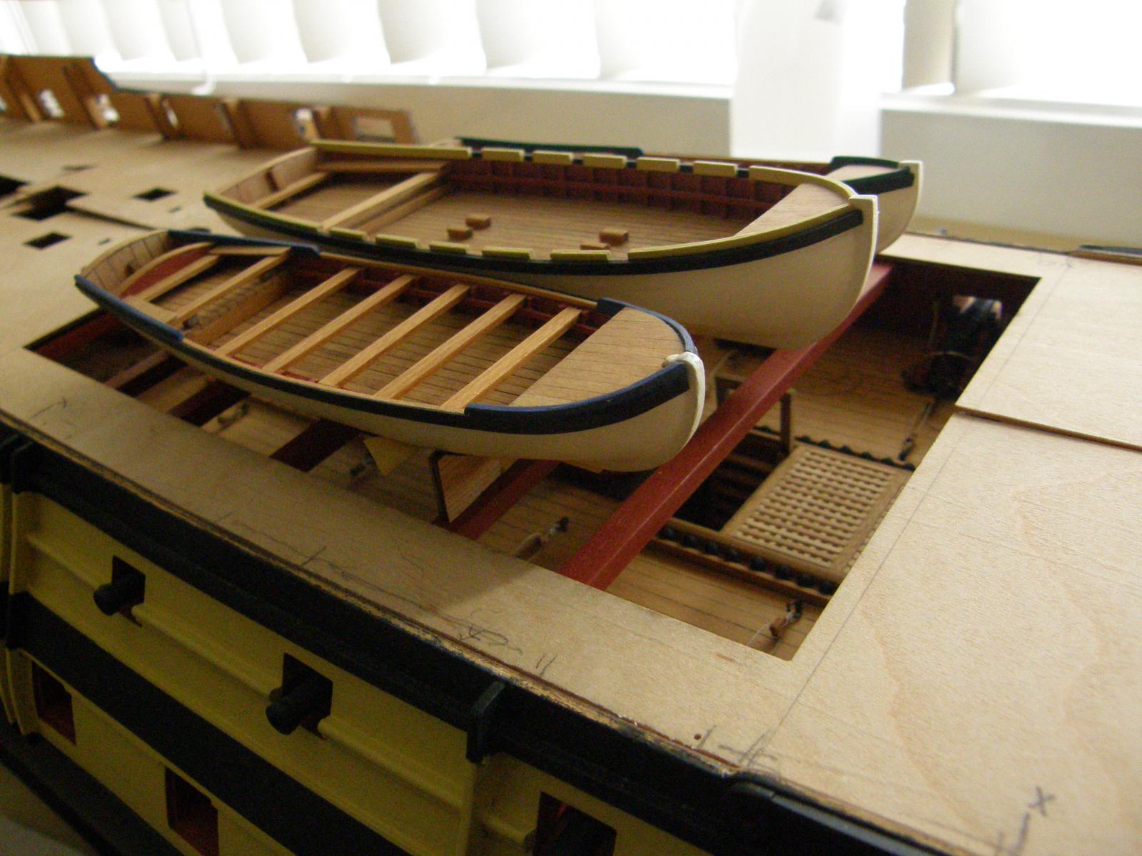
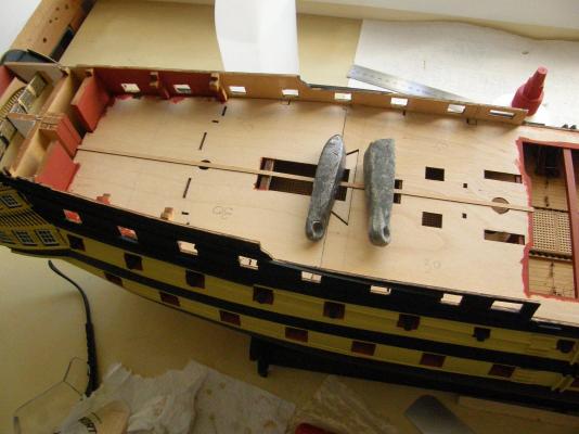
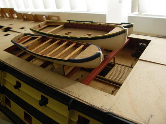
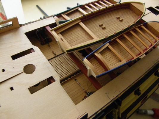
Progress has been made on the upper deck, though not without a careless mistake. I decided the best way to fit the boatdeck beams was to glue them in position before putting on the plywood deck. Doing so enables a firm attachment of the beams to the side of the hull. In each case, both ends of the beams needed to be trimmed off by about 0.5mm for a snug fit. I meticulously measured the gaps between each beam, and then for the second beam towards the stern, put the front of the beam on the mark instead of the back. The result is that the beam is 5mm out - which then threw the next one out too. Fortunately I was working from both ends, so the front two beams are fine. I discovered once I realised my mistake, that my gluing was all too effective. I then laid the boats on the beams to see how obvious the blunder looks, Fortunately, once the boats are on, the beams can hardly be seen. I guess the boat cradles will need some work to accommodate the problem, but correcting the position of the two beams would cause significant damage, for not much gain. These are the first of the beams - accurately installed. These are the whole lot - with blunder. The result is the gap over the capstan is 5mm too big. The second beam on the left is the culprit (I am now absolving myself from blame) , throwing it, and the next beam out by 5mm. Here are the ships' boats laid on the support beams obscuring (I hope) the mistake..


-
Thanks all for the comments and the likes. Alistair: I note that not only have you aged ( ) but you've been promoted too. Congratulations.
-
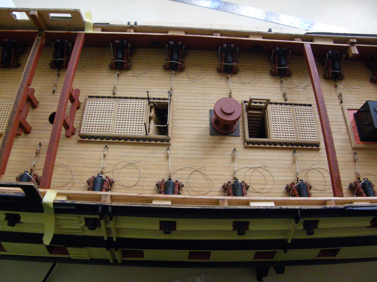
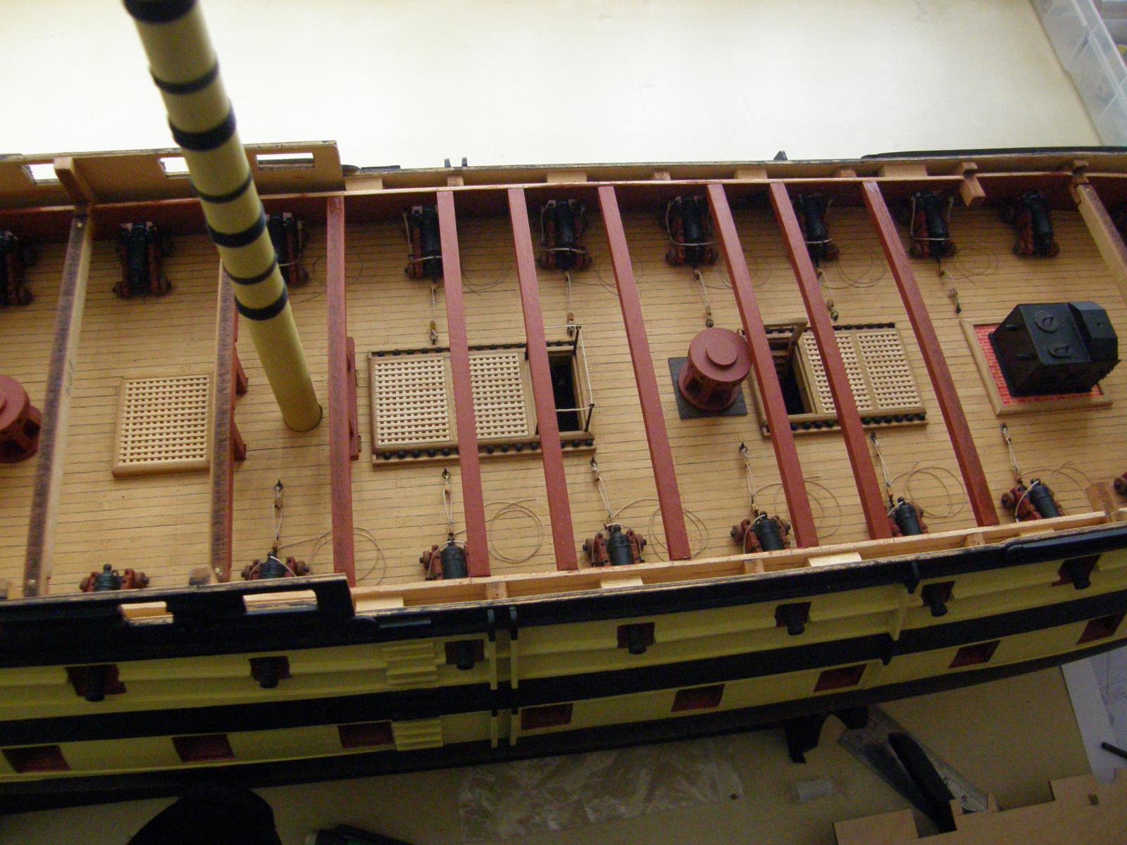
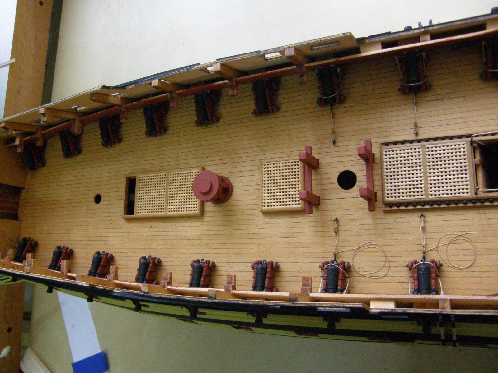
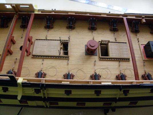
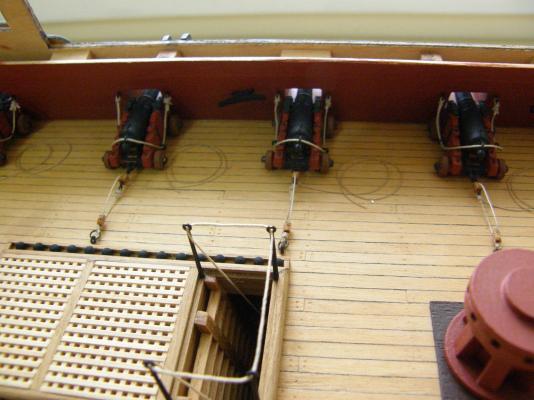
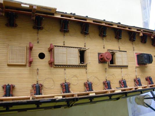
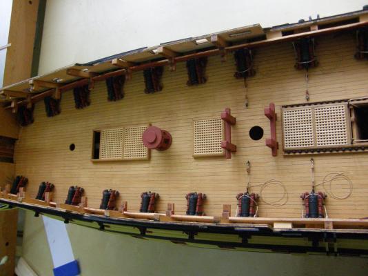
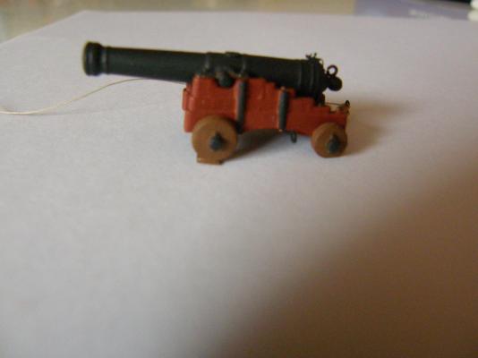
I have finally mounted the guns. It's something I have been putting off. Putting them on is the last thing to do before putting the 'lid' on the deck and I keep thinking I may have foregotten something - aside from where I put my car keys and glasses. I decided not to put the full rigging on them. To do so would require drilling two holes in the carriages to provide for eyelets and I don't have the type of drill that would do the job properly. As well, only the guns that could be seen were (partially) rigged. My committment to authenticity goes only so far. I am happy enough with the way it has worked out, though I am not enraptured with my rope coils. The thread provided went every way but the way I wanted it to go. The gun rigging, while fiddly, proved easier than I thought. Two pairs of longish, fine-pointed tweezers were indispensible. I am now looking for alternative sources of rigging cord that may behave more pliably. Suggestions are very welcome. To achieve reasonable uniformity of the heights of the gun barrels in the ports, I adjusted the heights of the guns towards the bow and the stern by grinding down the front wheels at the three stern ports, and the back wheels at the three bow ports. It is at the bow the difference in the heights of the gunports from the deck is greatest, and here I also glued a small piece of copper strip below the front wheels - two under the guns at the very front port. These can't be seen. Here is the gundeck.

- 949 replies
-
- 11
-

-
Arthur: My stem decorations needed a little trimming - a fraction top and bottom - to fit. You may have more luck.
-
Thanks all for the encourgement. I has just ocurred to me that I haven't really given much thought to mounting the model. I drilled a couple of holes in the keel, but I'm not sure what to do with them - if anything. I may just paint the stand provided, but if I do that I guess I'll have to do it now before the whole thing becomes more or less immovable. Suggestions welcome.
-
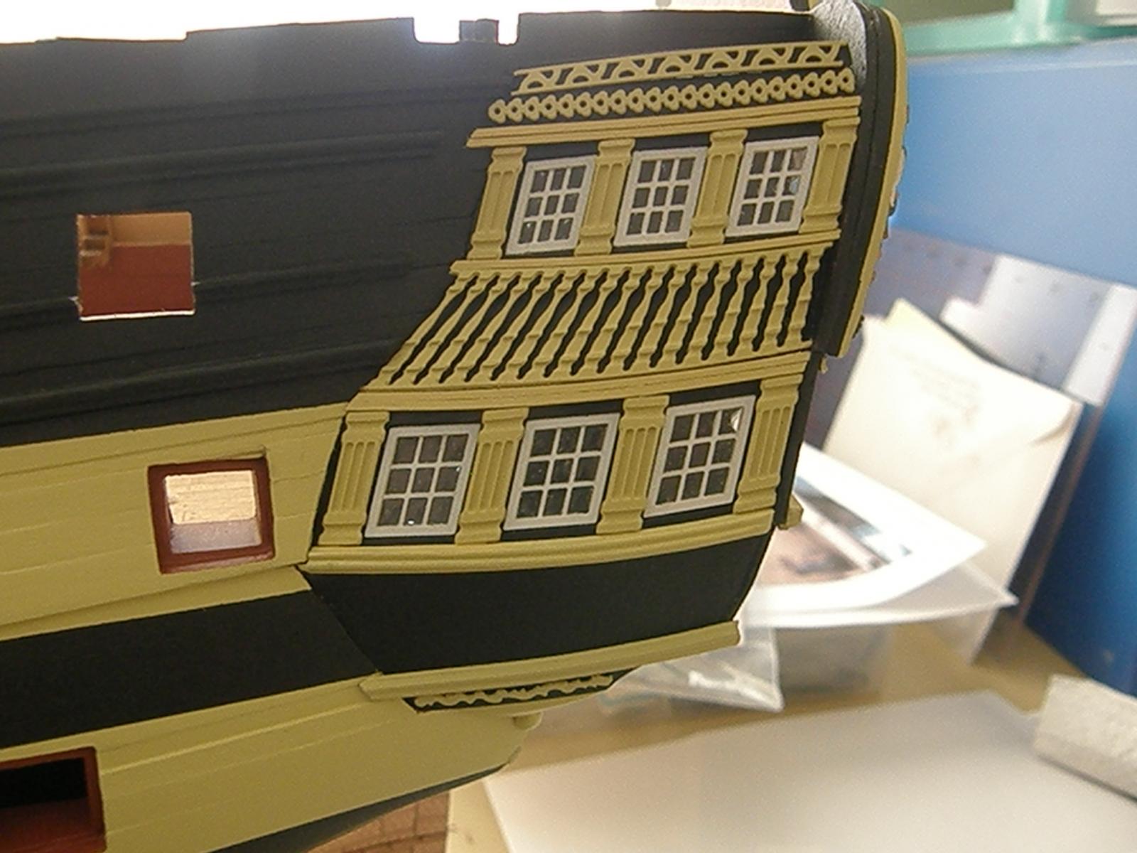
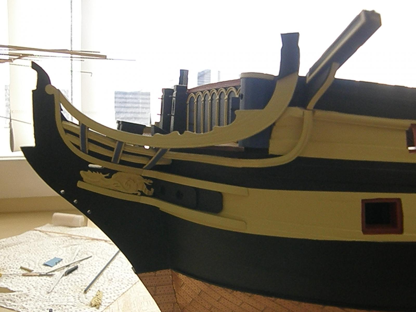
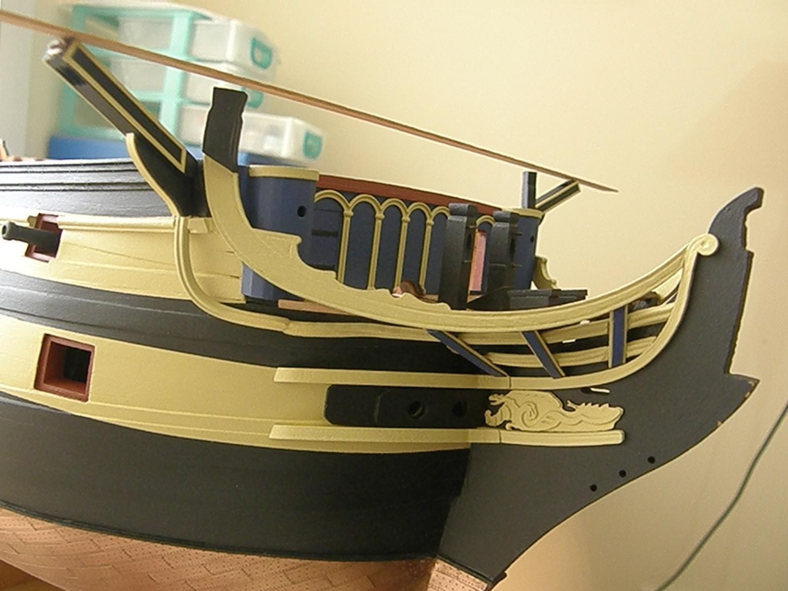
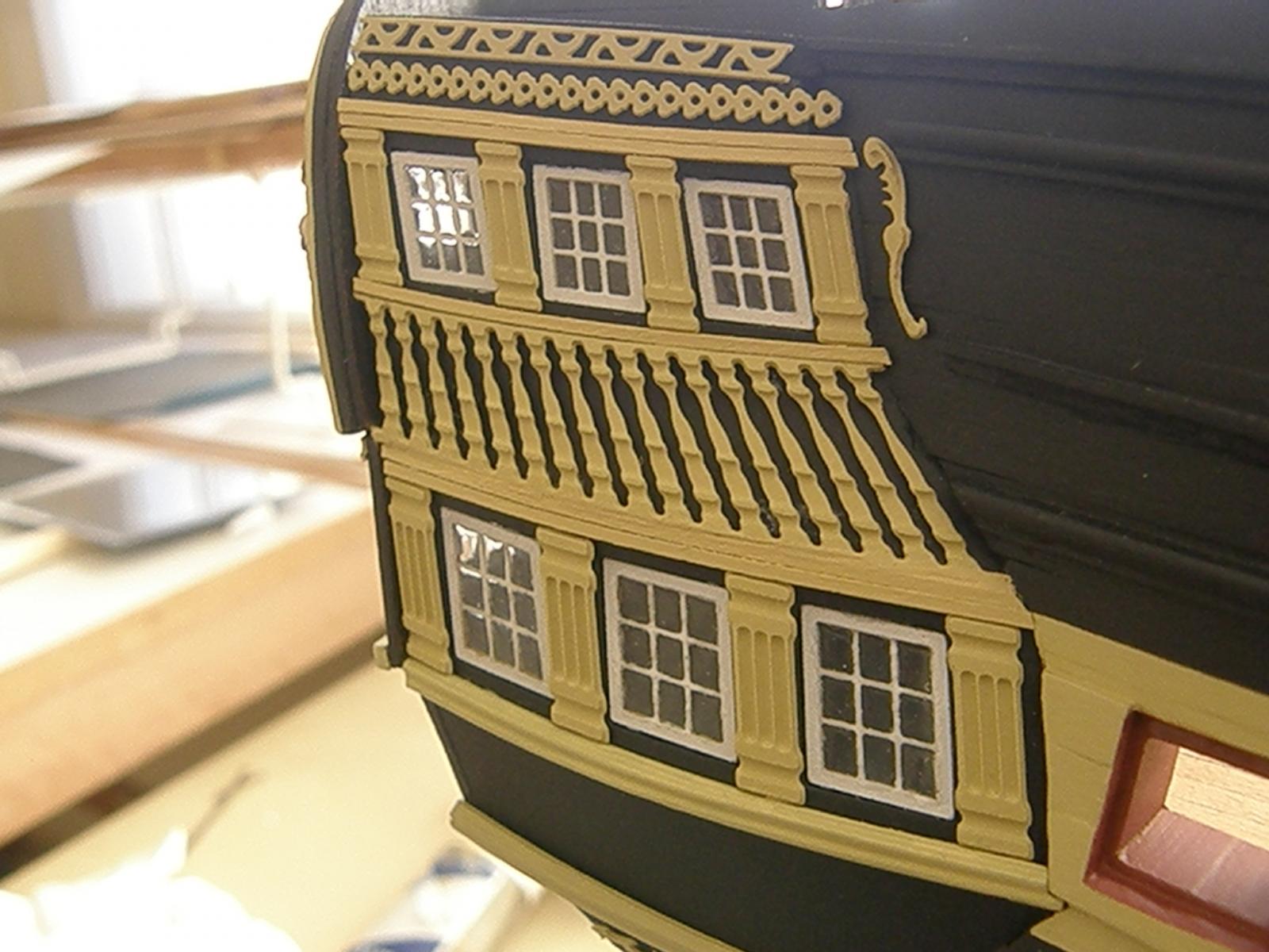
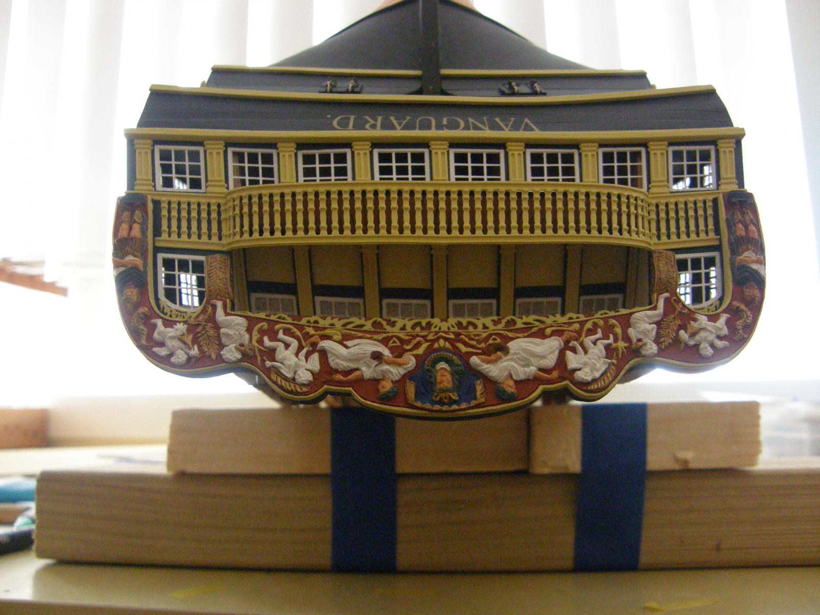
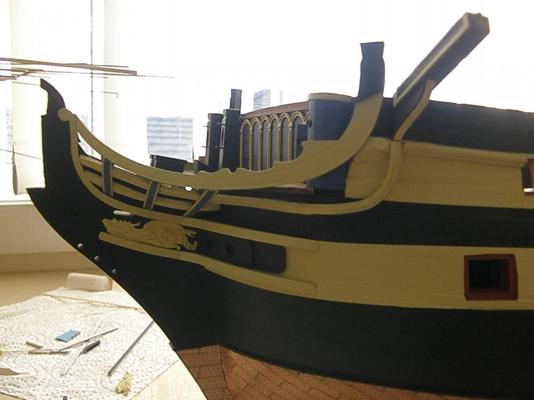
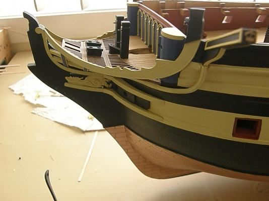
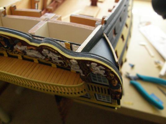
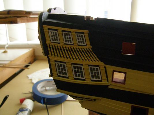
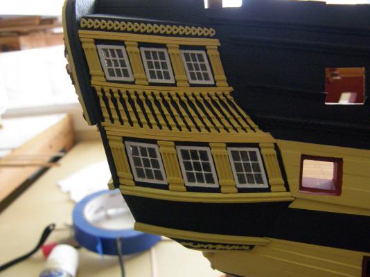
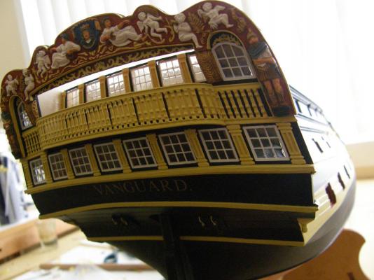
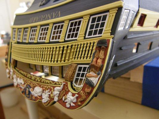
The side gallery decorations are now complete. I thought completing the right side decorations would, having done the left, be easier. naturally my expectations were disappointed. The large oddly shaped decoration refused to be glued. It took four attempts before the wretched thing went where it should. For those who try this in the future I have a fewsuggestions that may help. Start with a very complete vocabulary because it's likely you will use it. Bend the piece the conform with the curves of the structure of the gallery as best you can. The top and the bottom curves differ and essentially the whole piece is twisted. Glue the lower curve to the structure (I use dots of gel CA about the size of a pin head all over the back of the piece). Make sure it is firmly fixed at the bottom as it will be under stress. Initially, the top curve is almost certain not to fit - there will be a gap between it and the surface of the gallery. Now that the lower curve is firmly fixed, press the top curve to conform with the curvature of the gallery. It will bend to the right shape fairly easily, but keep applying pressure until you are sure it is firmly glued. Finally here it is. I have now more or less completed the bow decoration. The joining of the two bits of the middle rail - the one that meets the bottom of the cathead - went fairly well on the left side, not so well on the right. I had it lined up perfectly and applied pressure to complete the gluing - and the model then moved. The decorative bit moved down about half a mill and the 'moveable' gel CA then decided not to. To redo it risked significant damage, so there you are. The catheads and the bow timber heads are dry fitted in the photos. Putting them on at this stage, sticking out as they do, is inviting trouble.


- 949 replies
-
- 14
-
-
Thanks for the note Keith. If you are not already looking, the logs of AEW (Arthur), Free Wheeling Guy (Len) and Fake John Bull (Mitsuaki) are particularly helpful for Vanguard/Bellerophon builders. All the best., Bob
-
Thanks for the kind comments BE (Jason?) and others for the 'likes'. Encouragement is always ... well ..... encouraging. I wasn't at all happy with the rudder straps but I now have a better perspective of it. It just shows that (my) ignorance is not necessarily bliss. Regards to all Bob
-
Something odd happened to my post so ......
-
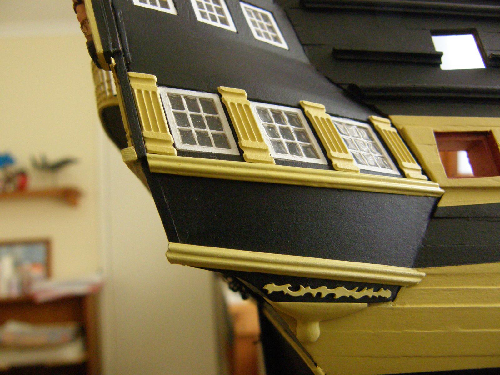
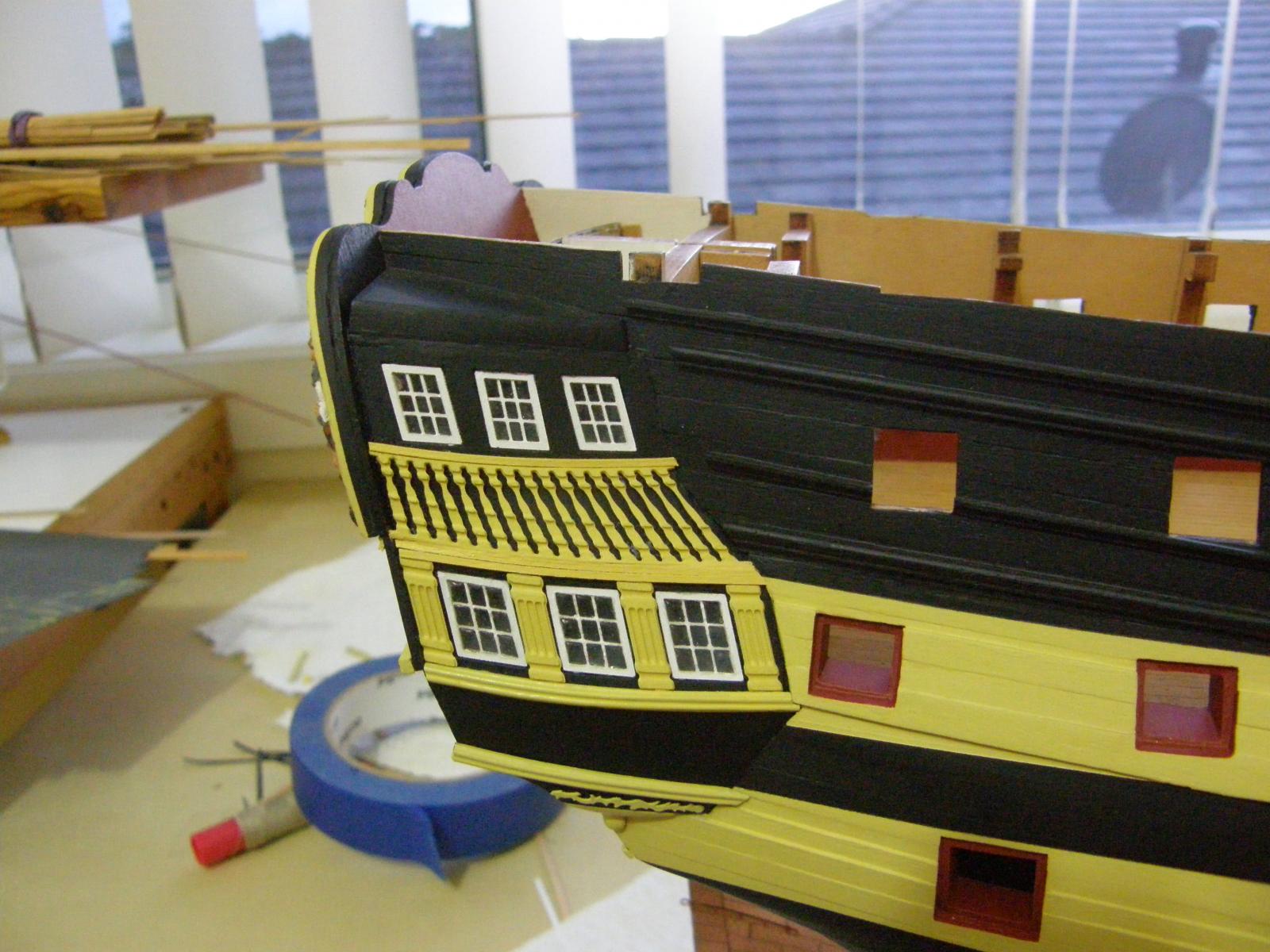
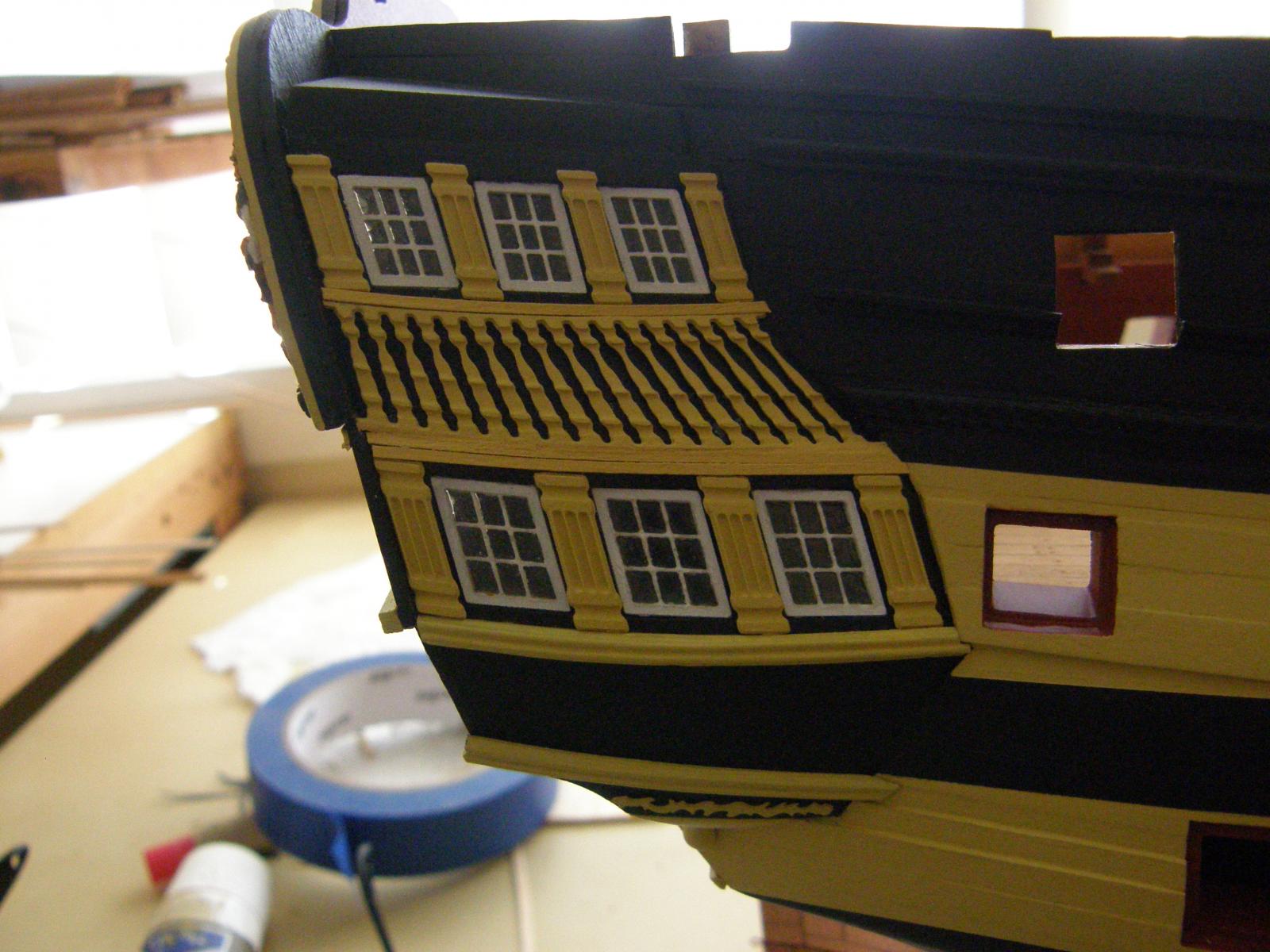
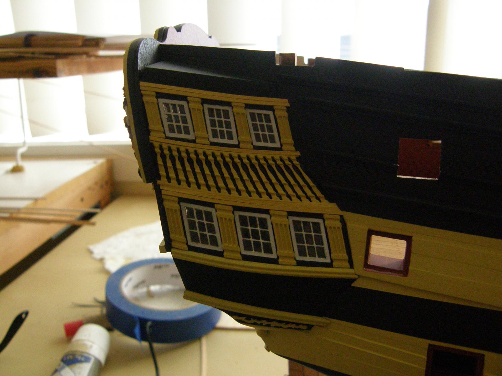
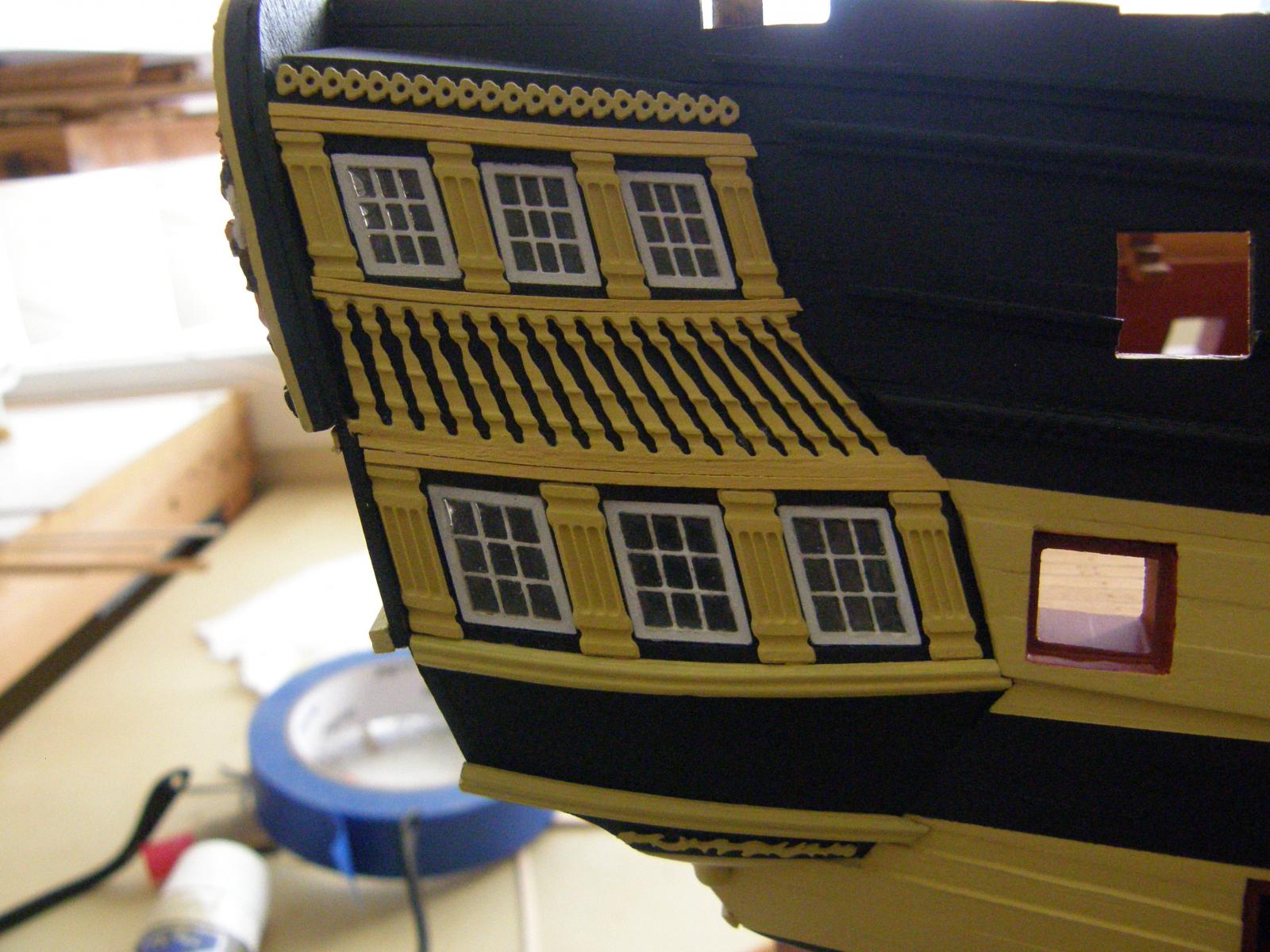
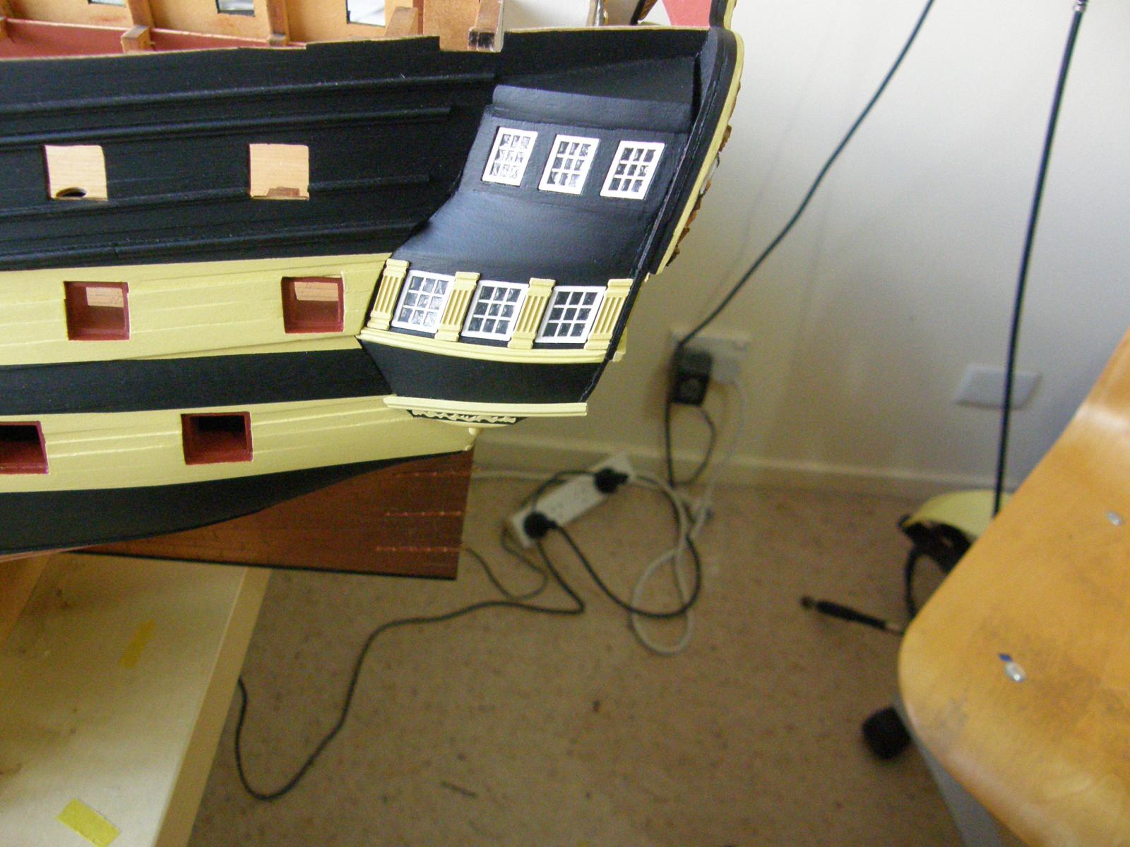
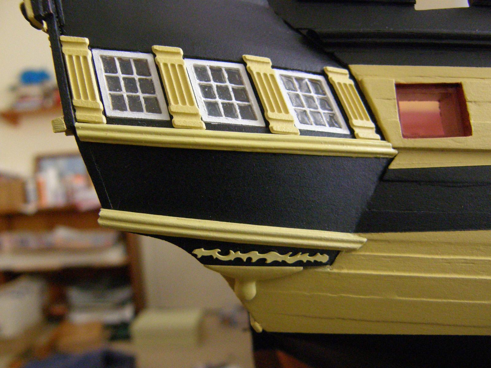
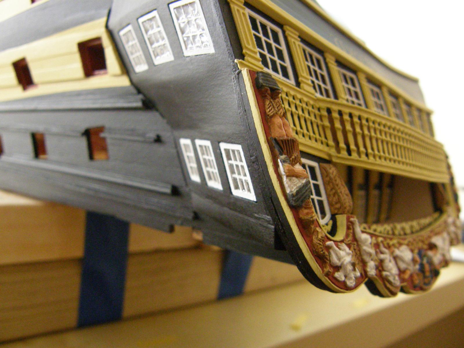
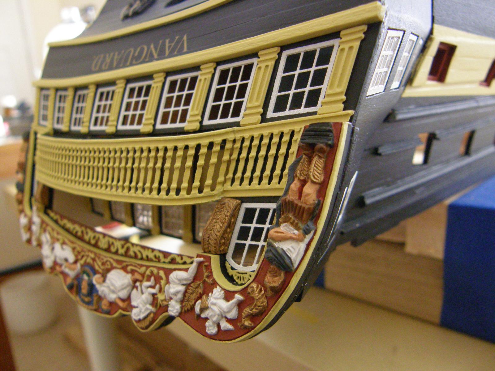
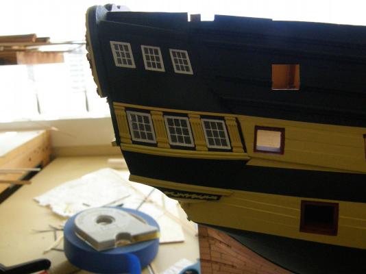
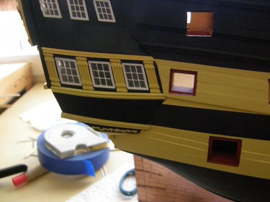
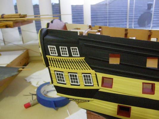
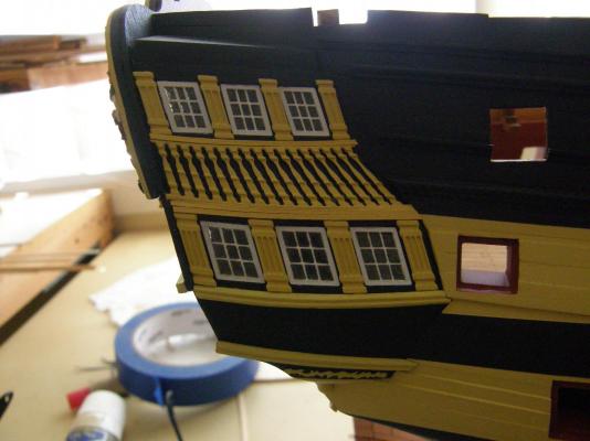
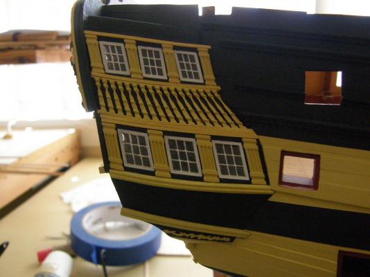
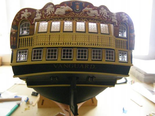
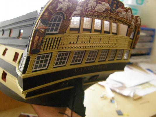
I have finished the decoration of the side gallery on the right side of the model. The fit of all the decorations relies on the accuracy of the underlying structure. It turned out fairly demanding with a few heart-stopping moments. I have photographed each step in the hope that it may help future builders. A piece of strip needs to be attached to the very top of the gallery apparently for the sole purpose of decoration - which seems a bit odd. Definitely pre-bend the strip to the required curvature. Two pieces of 1x1mm strip are glued to the tops of the pillars. Then the rather strange curved decoration was applied. I bent it to shape as best I could beforehand. Getting the bend completly right off the model was well-nigh impossible so it was glued on under some stress (both the decoration and me). Fortunately it turned out quite well. The fit was quite close, but at the bottom of the decoration there were small gaps at either end. I used wood filler to fill them. And here are the remaining steps. Before applying, the decoration should be bent to shape of the underlying structure and laterally to conform to the curve of the strip below it. The very top decoration proved impossible to bend laterally. As a consequence I glued it at a slight angle to give the impression of it conforming with the lateral curvature of the decoration below it. Except for some very minor touching up :finished. Now for the left side .....


- 949 replies
-
- 13
-
-
Alistair; Dunno if I'm overly hard on myself. I think it's more a product of shortsightedness. I can see every fault.
-
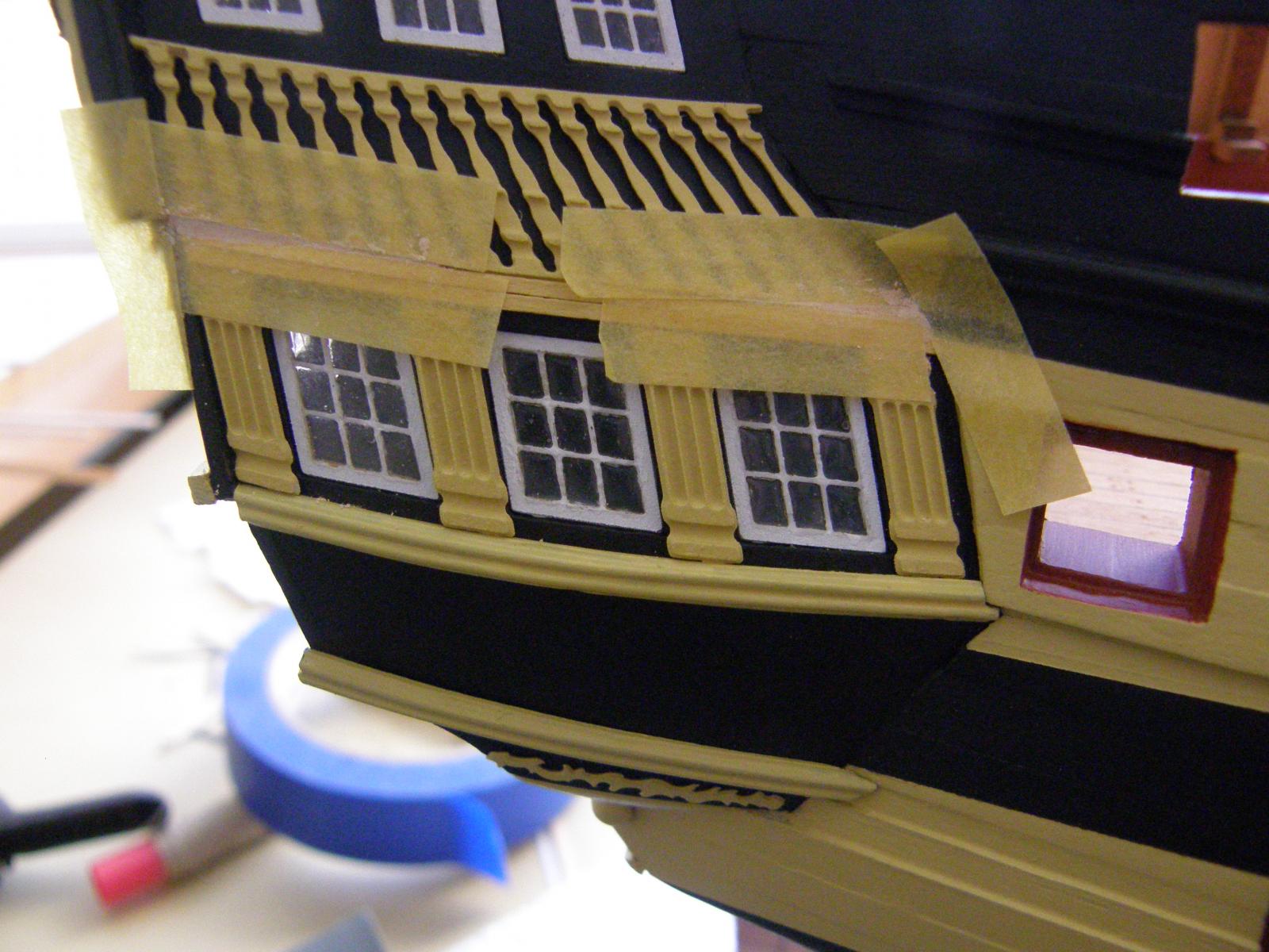
The rudder is finished and painted. I'm not all that happy with it. Even after spraying wiith the PS 55 it still looks too bright and obtrusive. At least in the process I was able to repair the slight damage to the clear coat over the copper bottom. I guess all the decoration near the rudder will tend to draw the eye away from it - at least that's what I'm hoping. As I was typing this I realised that I have some copper strip that would have been ideal. In the meantime I have started the decoration of the side galleries. Here there are a few mildly annoying problems. 1.The layout of my brass assembly differs from the plans. As a consequence I went close to carelessly putting one of the pillars in the wrong spot. Moral: dry fit them all before gluing. 2.According to the specifications there should be 4 of Part 377. There are 3. It doesn't matter as the length each each one is more than sufficient for the purpose with quite a lot left over (you have to cut them off) - unless there is another application that I have overlooked. 3.There is not enough room to fit decoration 434. If 436 is to be applied in front of the forward pillar, if it is painted yellow (as I have) it will more or less disappear from sight. I'll think about painting it black or leaving it off altogether. Here are a couple of progress photos.


-
Alistair: I have painted them copper. The paint ,as I mentioned above, is a bit of a pain. I would have preferred not to copper them as I quite liked the look of the'iron'. - but authenticity is everything .... well. within reason. That's why I went for fewer rivets and not as many heart-stopping moments.
-
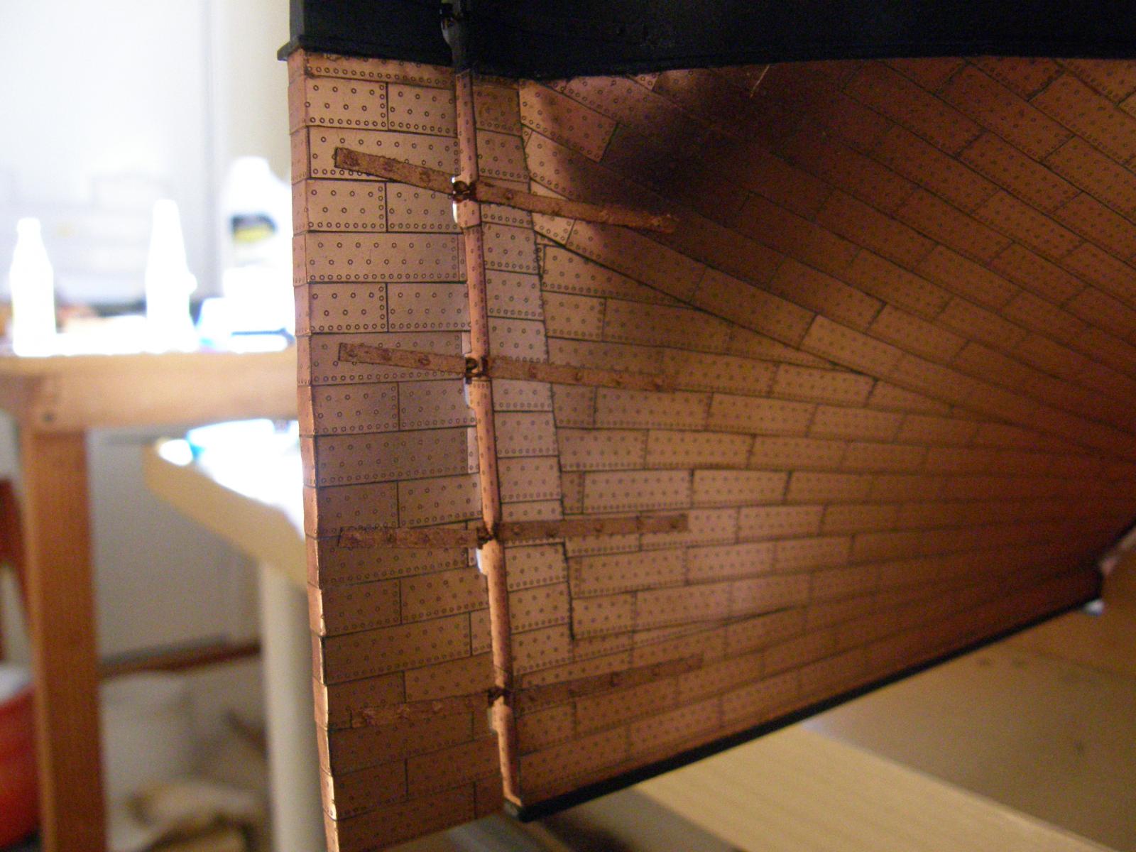
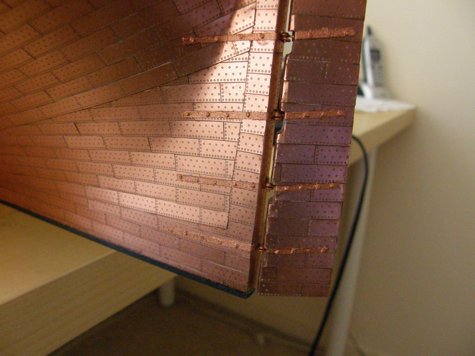
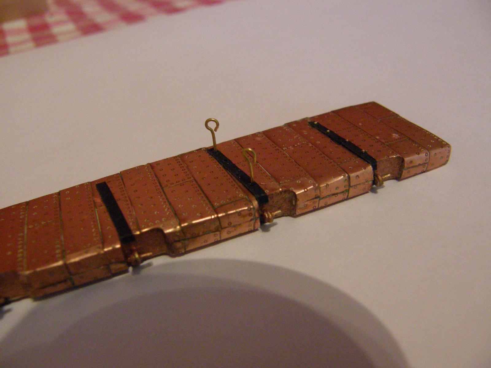
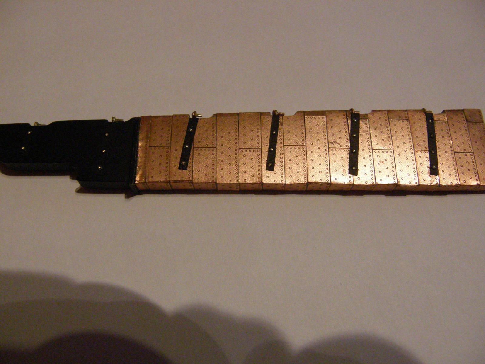
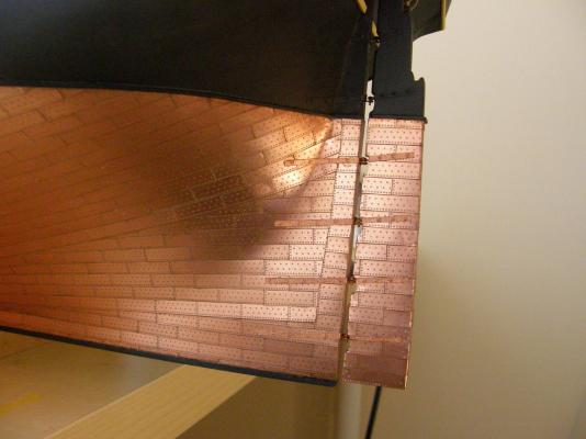
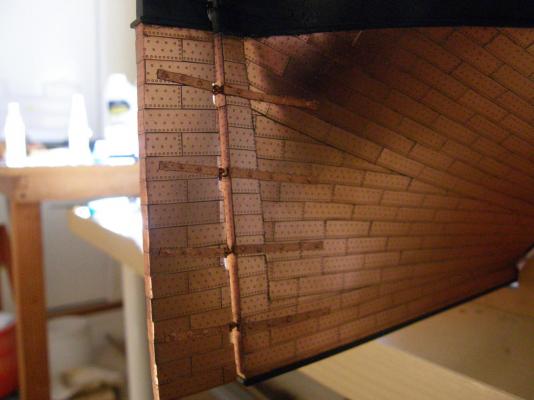
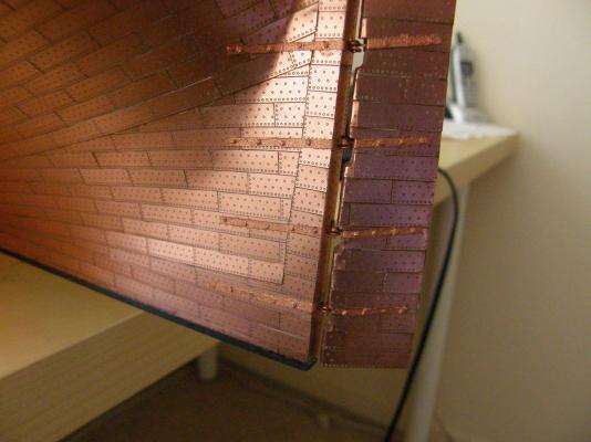
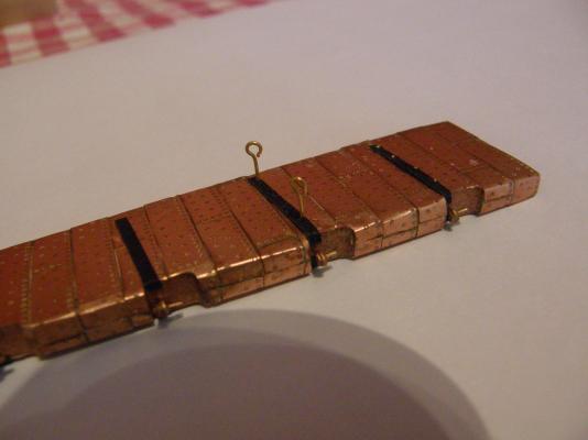
Here are photos of the model right way up. I have just finished the straps for the rudder. Rather than use the kits parts, as suggested in the instructions, I used cartridge paper, though I wonder whether it has been a really good idea. I decided not to use as many 'rivets' to save drilling more holes than a swiss cheese as the potential for damage is high. I filled the holes with copper wire from some spare eyelets (a tiny bit of gel CA at the bottom) , then snipped off the wire almost flush with the surface of the rudder. The wire standing proud of the surface together with a tiny bit of gel CA which came to the surface 'made' the rivets. It worked moderately well. Here they are before painting. This shows the eyelets before my snipper got at them. Their painting is now complete - photos awaiting the paint to dry. The copper Humbrol paint is quite hard to work with. It needs to be constantly stirred, tends to be gluggy when applied, and the brush needs to be cleaned often. Moreover the finish is very bright and does not match well the rest of the copper. I am hoping that the brightness will be toned down when I spray a couple of coats of the Tamiya PS 55 flat. Incidentally the PS 55 is fairly easy to damage and I would probably not use it again in this application.

-
Arthur: thanks for that.
-
Alistair: thanks for the encouragement - it's appreciated. The model is the right way up now and I have just hung the rudder (though I will take it off for safety). (I'll post some photos when I get back.) I am going to give model railway dummy rivets a try on the rudder straps as drilling a total of about 100 holes in the rudder and hull certainly does not appeal.
-
I will be away for a few days and may get a chance to work on the masts. I have a question. The instructions (lower p.11) say to paint black 'the area in between the bottom of the bibbs up to the lower mast cap black'. There is no mention of 'bibbs' in the parts list and what appear to me are the bibbs (eg part 156 - a shape that looks a bit like a painter's easel) are specified as hounds in that list. "Hounds" then are described as the "conical shaped area" on topgallant mast(s). Can anyone tell me what is going on?
-
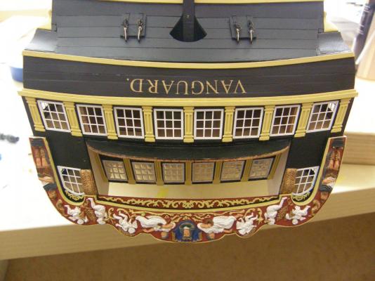
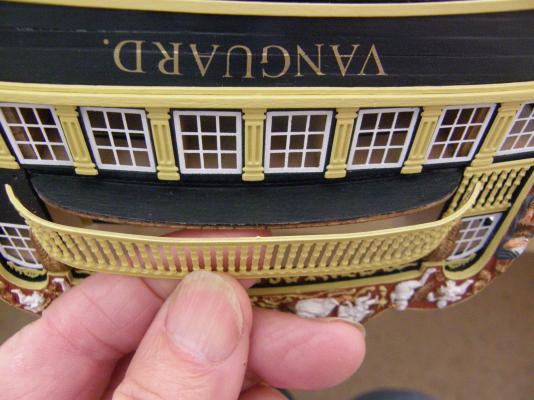
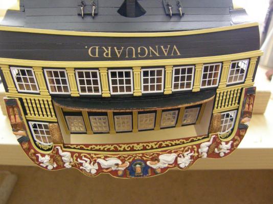
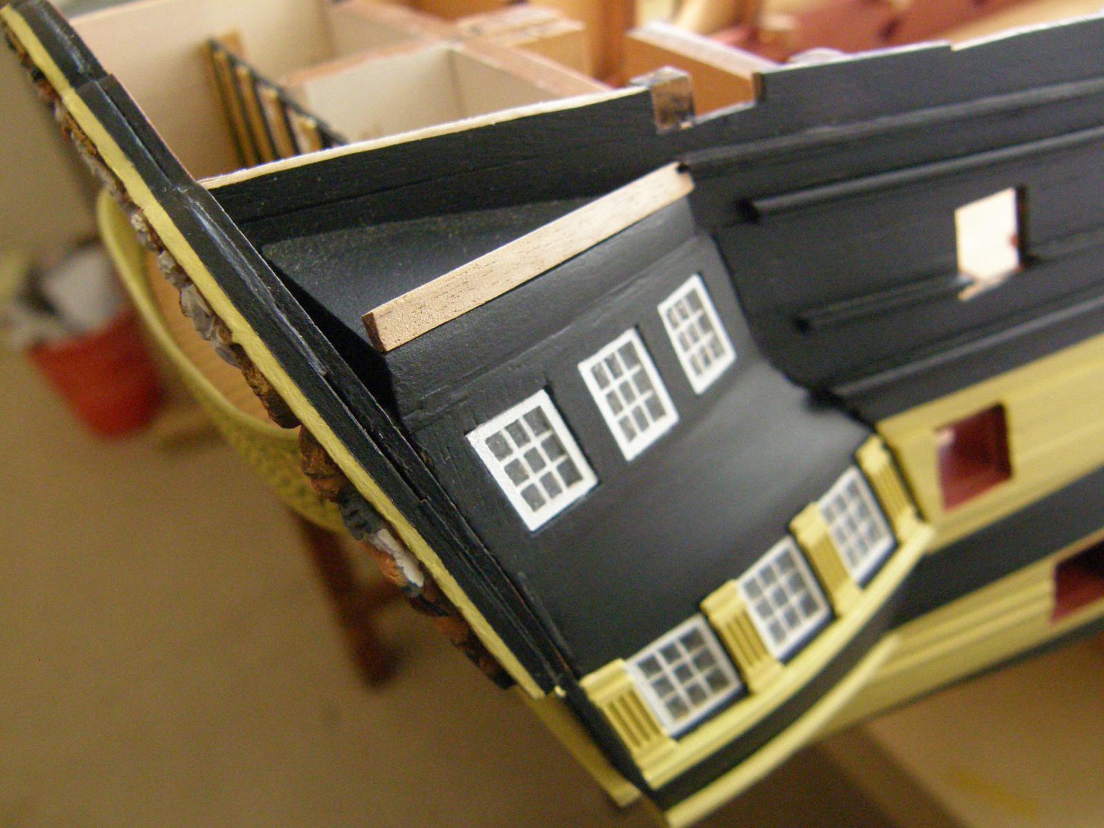
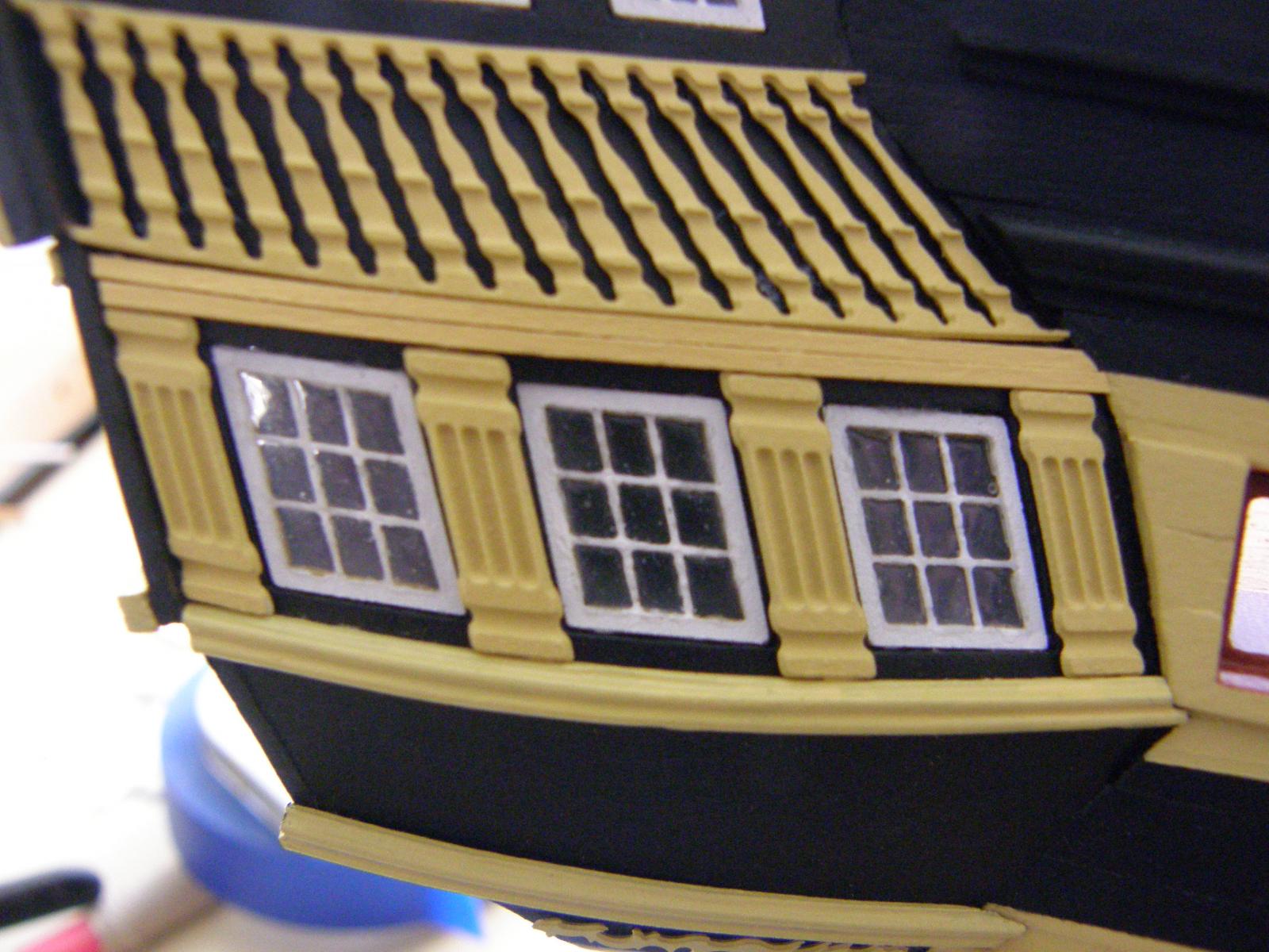
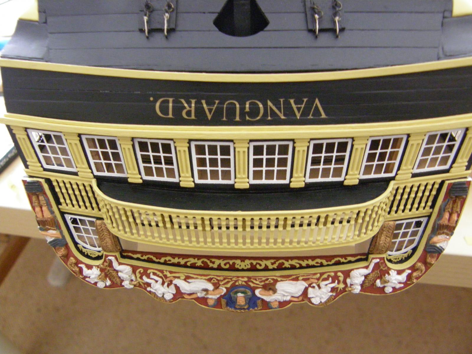
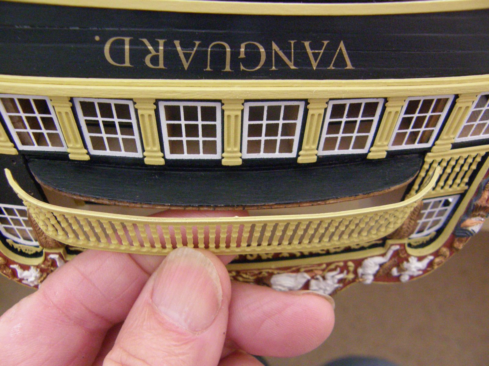
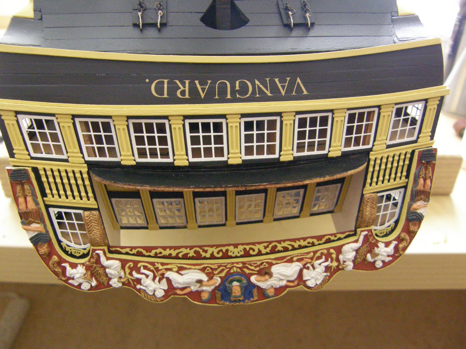
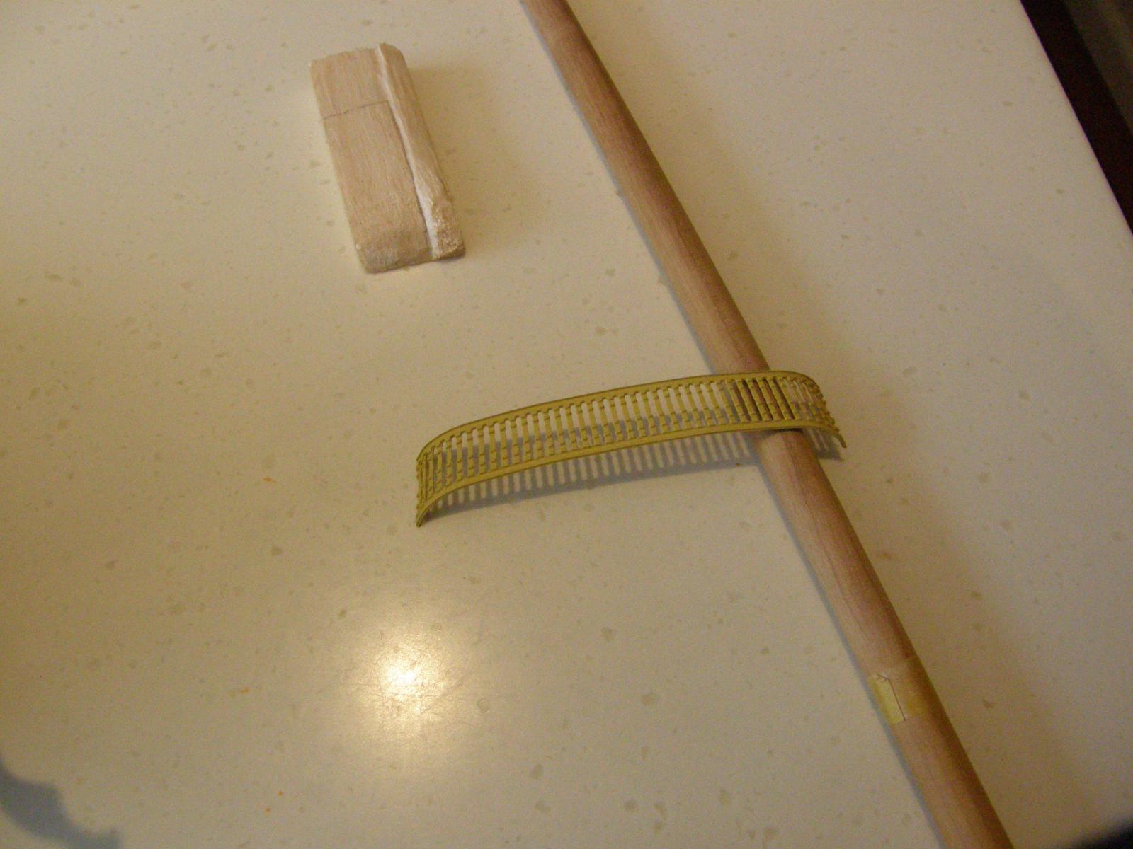
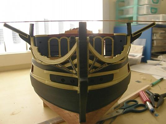
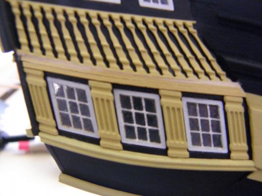
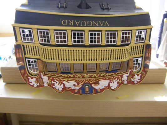
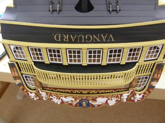
The curved railing is now installed. It has come out quite well considering. The fit of the curve could be slightly better and with hindsight I could have taken off another 0.5mm off each end. There is a slight gap between the balcony and the railing at each end, but can't be seen and I can live with it. Since taking the following photos I have glazed the windows with Kristal Klear. The KK does a really good job and is fairly easy to work with once you get the knack - highly recommended.


- 949 replies
-
- 12
-
-
Arthur: a couple of things I forgot to mention. In the instructions (p.12) in the lower drawing (the complete stern window/railing etc) there are shown three lots of 514 decorative strips. Those specified at the top and bottom of the railing have to be wrong. The top and bottom of the railing are already 'decorative' and aside from this the 514 decorative strips simply don't fit. As well the curved railing is a little too long. I needed to trim about 1mm off each end to make it fit. I decided to fix the two flat pieces of railing first, and then the curved part. I guess I will soon find out if this was a good decision. Good luck.
-
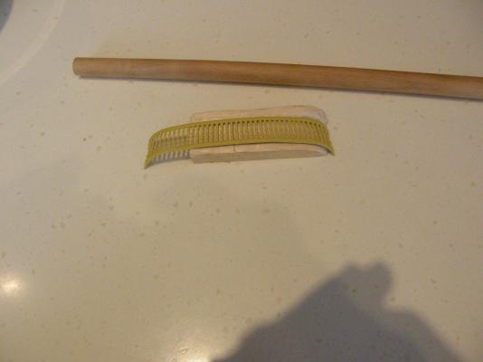
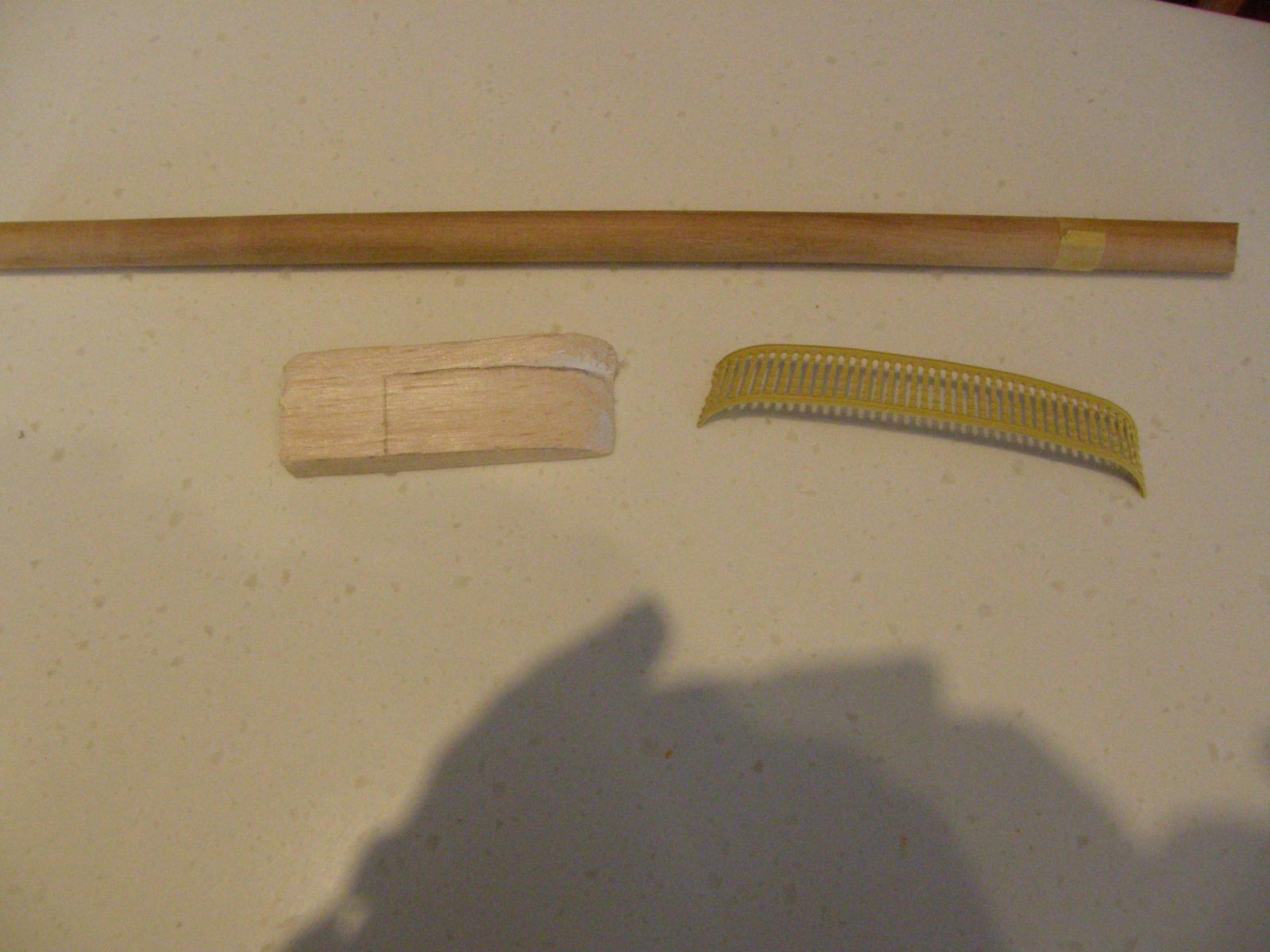
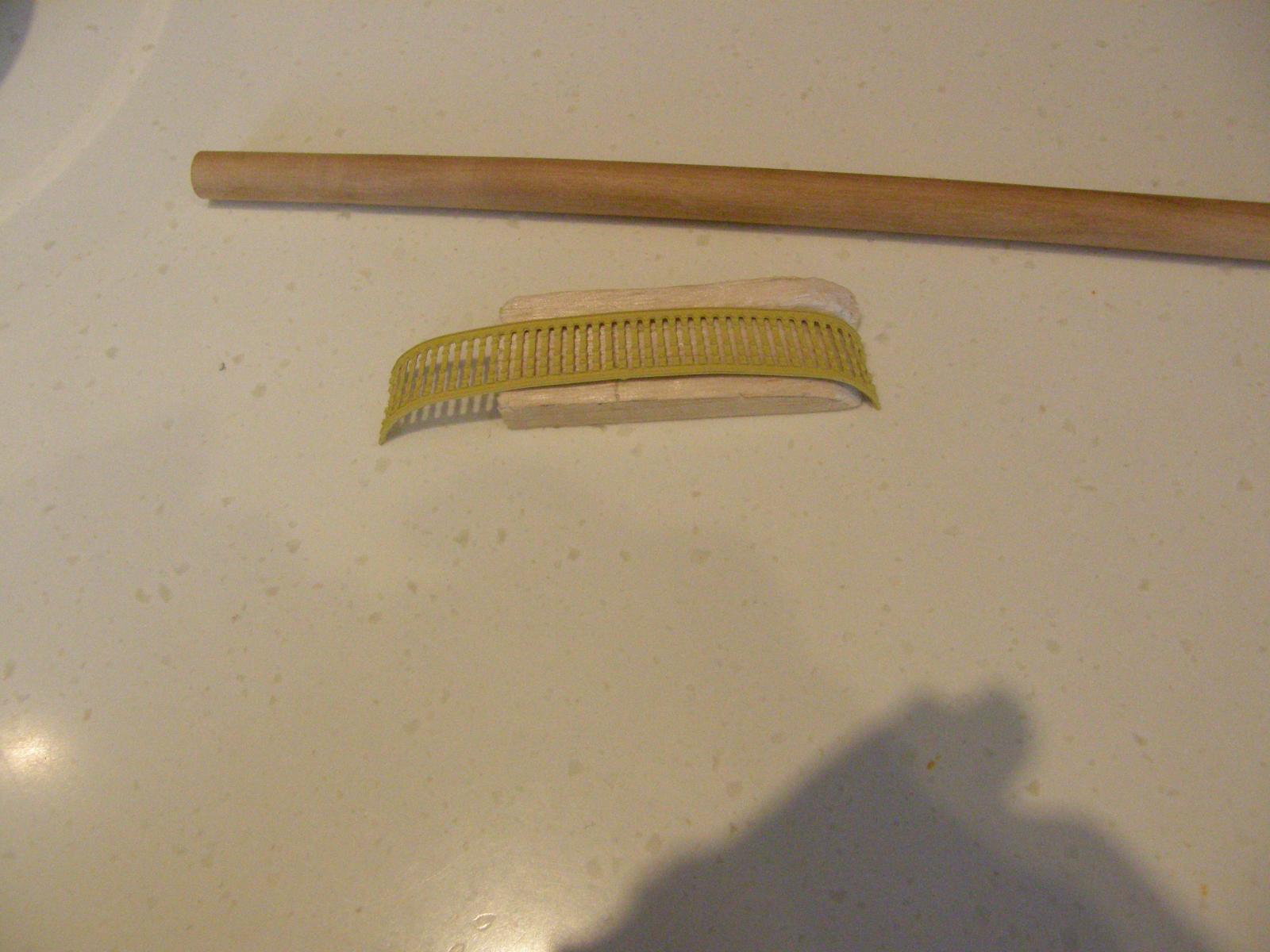
The stern railing and asociated bits is something I have been putting off. Bending the railing to conform with the shape of the balcony was a real concern. It turned out to be not so hard. I carved a piece of balsa to the shape of half of the balcony then bent half the railing to the shape of the balsa. The railing was then turned around and the other half was bent in a similar manner. Doing it in this way meant that the bends in two halves of the railing were at least identical, even if the overall curve curve was not quite right. It turned out that a little more bend was required on both ends. For this, where a greater bend was necessary I used a piece of dowell as support when I applied pressure to make the bend. The bend in the railing has turned out to be virtually identical with the curve of the balcony. I hope the next three photos will give an idea of the method. Actually attaching the railing is likely to be not so straighfoward at all. If you look closely at the third photo, the flat decorative part of the railing on the right side is about 0.5 mm out. This needed filing to enable it to fit between the main decoration and the column.The problem shows up with the small gap between the top of the flat railing and the window. There is no such gap on the left side. It's just annoying as the problem could have been avoided with a bit of foresight. - always dry-fit. More serious, the problem I and others have had with the plans concerning the height of the floor of the balcony and the stern facia has come home to roost. My solution to that problem was to make the stern facia (Pt117) about 1mm or so lower than the bottom of the balcony - I then filled in the gap. This all means that the curved part of the railing, to conform with the flat parts on either side will be about a mm or so too low when attached ot the balcony. In fact you will be able to just see the edge of the balcony though the railing. I have dry fitted the railing and fortunately it doesn't appear to be really noticeable. I have now painted the edge black and hope that this will further disguise it.