HOLIDAY DONATION DRIVE - SUPPORT MSW - DO YOUR PART TO KEEP THIS GREAT FORUM GOING! (Only 13 donations so far - C'mon guys!)
×


RMC
-
Posts
933 -
Joined
-
Last visited
Content Type
Profiles
Forums
Gallery
Events
Everything posted by RMC
-
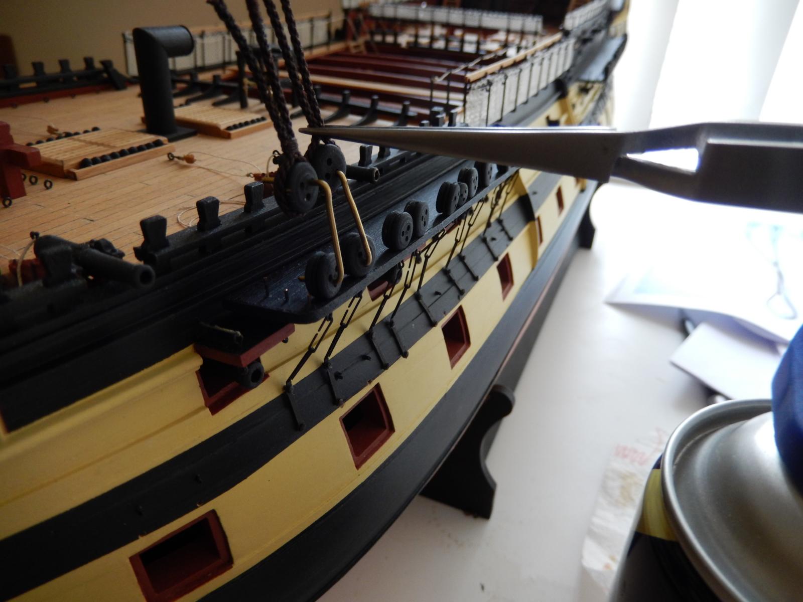
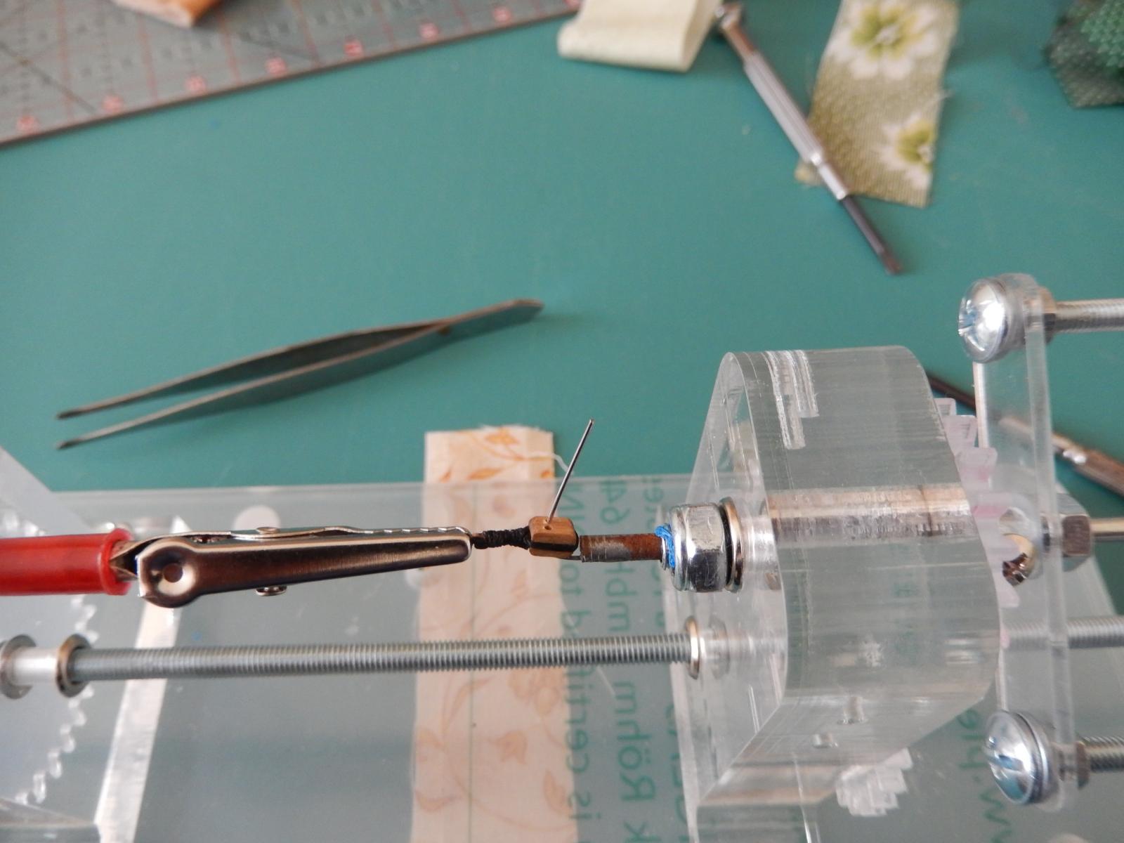
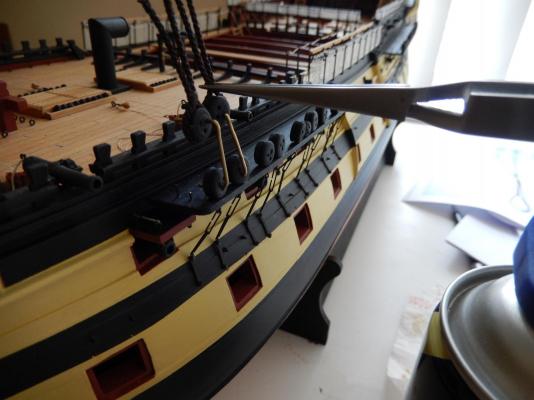
Brian: thanks for the alligator clips idea - it worked a treat. I have been working on the shrouds for the foremast. Serving the first shroud makes the resulting 'rope' quite stiff and a little difficult to work with. The result however has been quite good, though the process has been a little frustrating. Whatever I am doing in fitting the shrouds, there has to be a better way. If anyone has suggestions I would be grateful. First however, after procrastinating for as long as possible, I finally fitted the top to the foremast. Her is the fore topmast dry-fitted A bit of adjustment is required but it's not too bad. This is my rather inefficient method of attaching the shrouds. First by putting the loop around the mast, measuring as best I could, the distance down to the front deadeye. The position of the deadeye is fixed using fine and very strong spring tweezers. It is dry-fitted and its position adjusted if necessary so that the rope is taught. The deadeye is then glued in position. The procedure is repeated for the second deadeye. While the result has been quite good, (haven't yet taken any photo) there has to be a better and less time-consuming way.


-
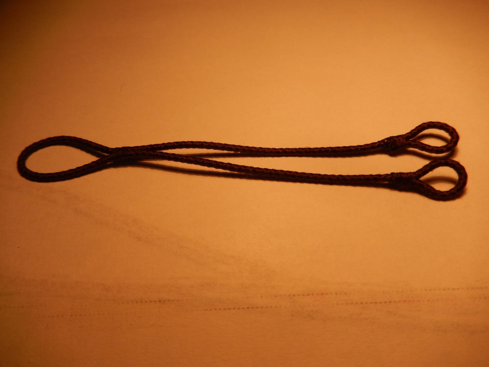
Arthur: pendants? - look closely - I have For the other: the Syren stuff I have used is 1.37mm + any serving = approx 1.6mm. The next size of the Syen is too big (after serving ) so the 1.6mm has to be it - though I will do some experiments on the larger size.
-
Alexey: I have sent a note to you - whether it's useful or not ....... A clearer video is a very, very good idea. Brian: thanks for the suggestion. I did have the end pieces as close as possible. Your suggestion of alligator clips is an excellent one. It may make my suggestion to Alexey redundant. Arthur, a bit belatedly: the thickness of the served pendants is 1.6mm so that's looks to be about right for the collar!
-
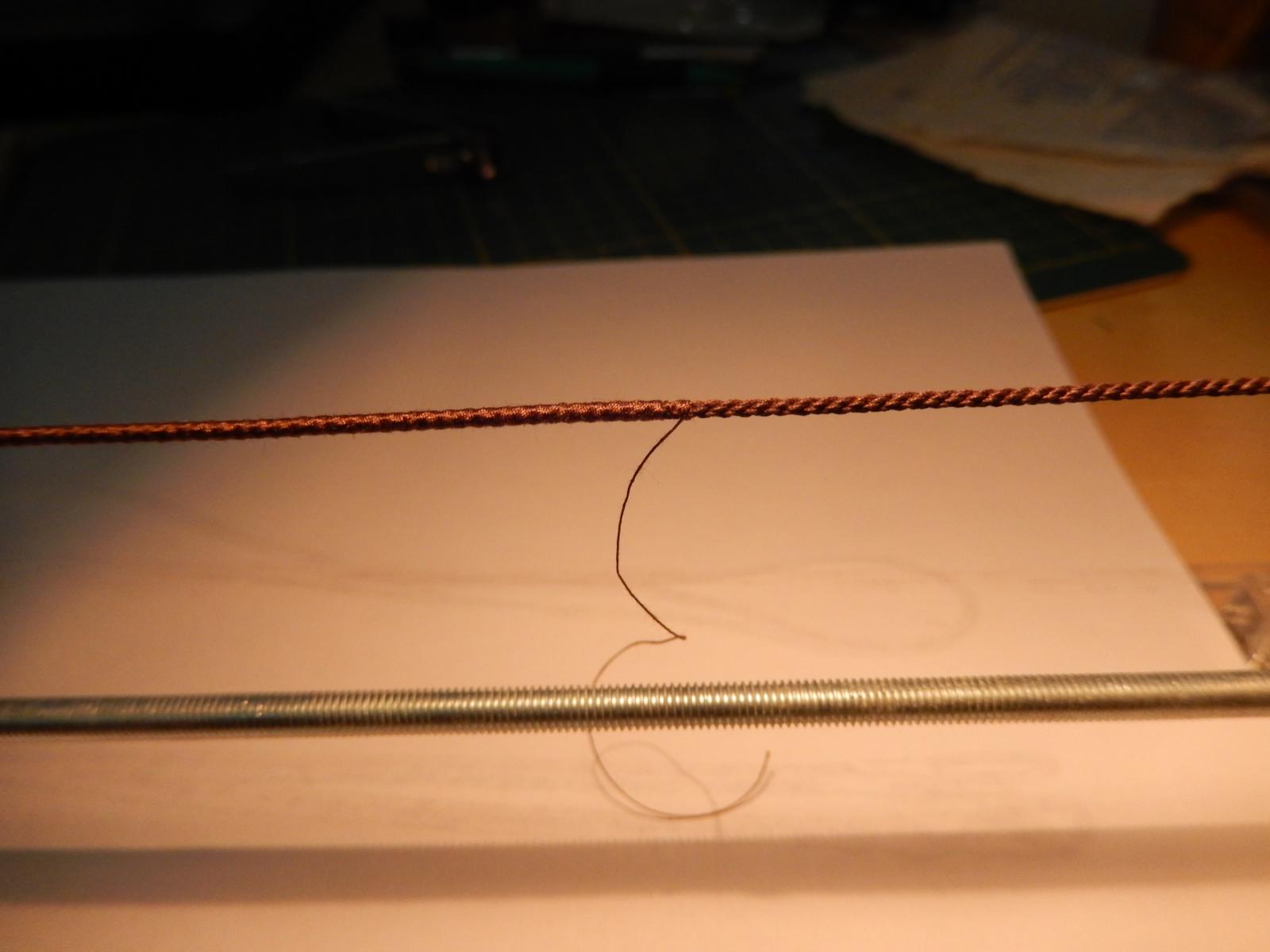
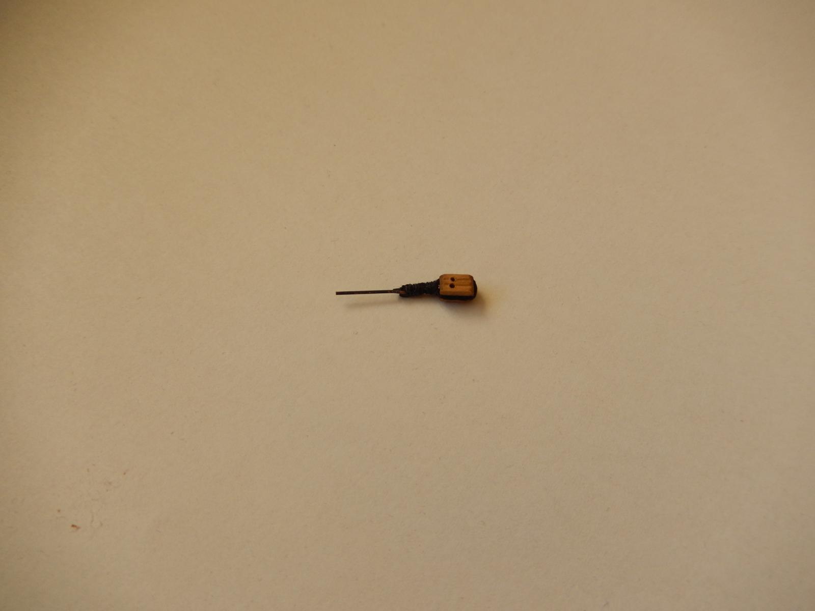
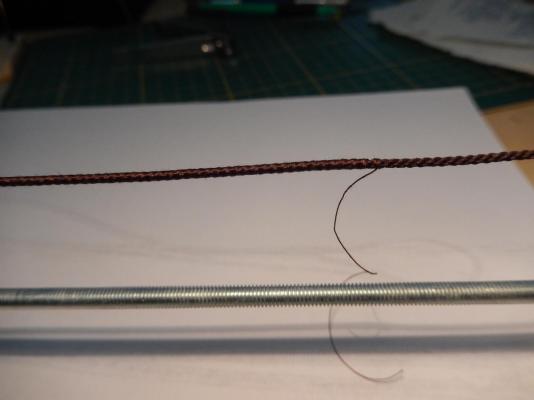
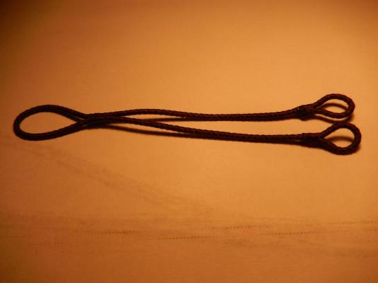
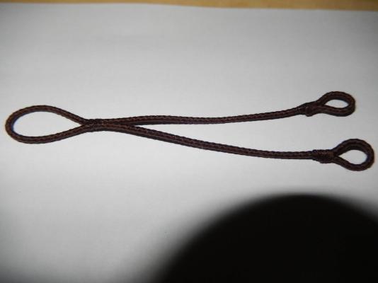
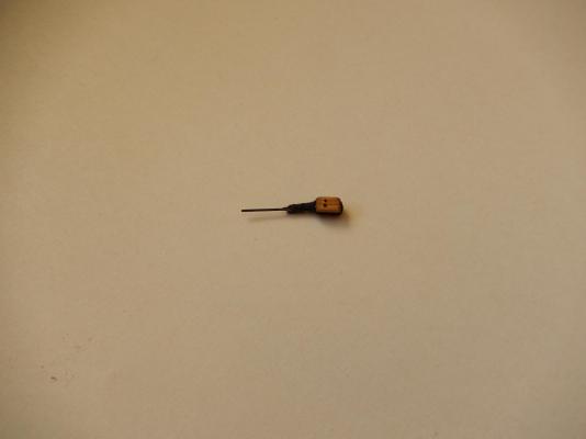
I have now made my first attempt at serving. It's something I've been putting off for a while. The result has been acceptable, but I am certainly hoping that practice will bring improvement. Alexey Domanoff's machine certainly does the job, though it takes a bit of getting used to. I found it a little difficult to keep the thread taught - mainly because of my poor knot tying. It is also a bit wasteful of thread, and as I am using Syren thread, perhaps I am a little more sensitive to this than otherwise. I have a suggestion for Alexey that may help mitigate problems for people like me that I will send to him later. Incidentally, I find it ironic that having gone to the trouble of buying in the Syren thread, I'm now covering it up. I have made one set of tackle pendants. Never having heard of them (not that that means much), I would have overlooked them altogether, had I not read the instructions. It just goes to show ...... Here more practice is needed to finish of the ends of the loops.

-
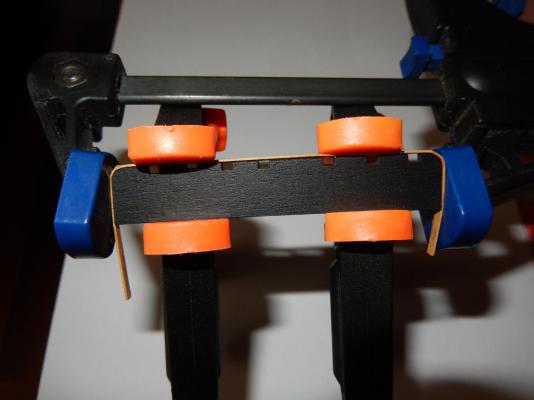
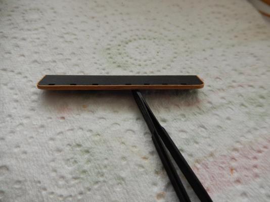
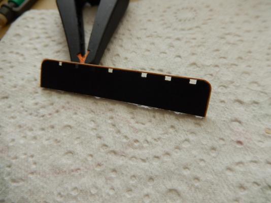
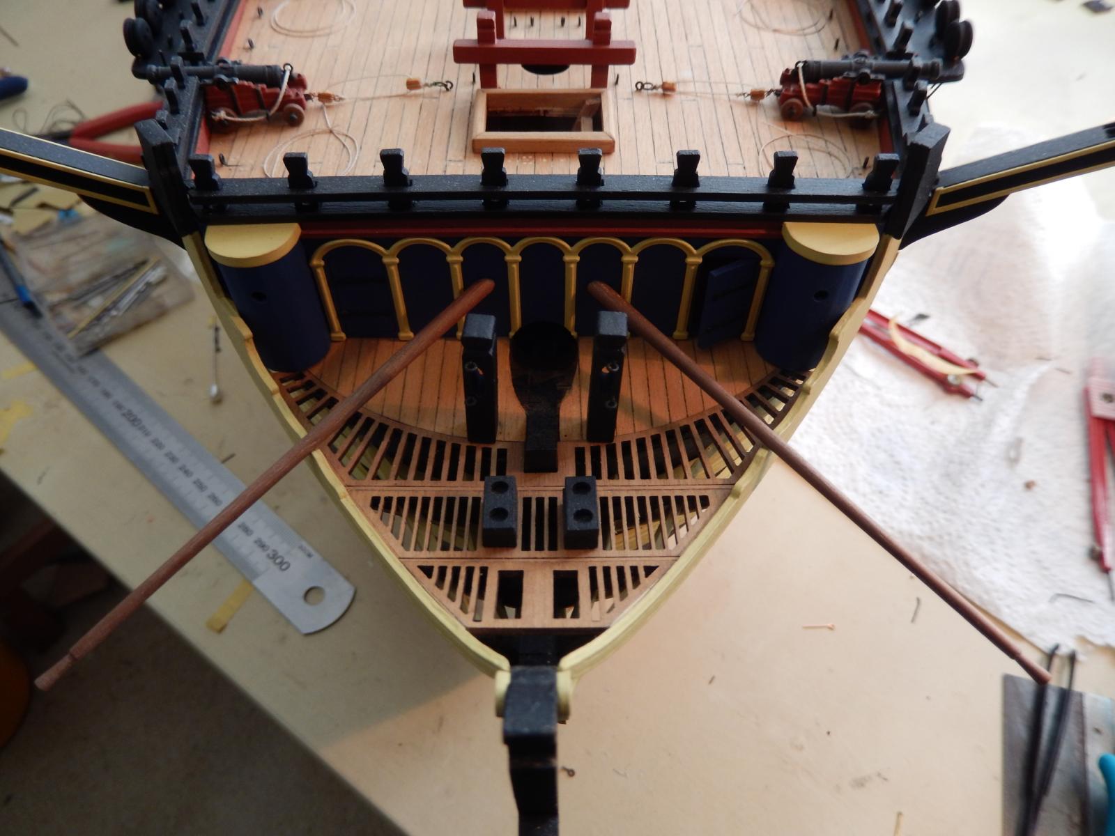
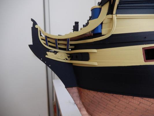
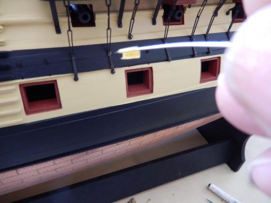
I made an unpleasant discovery - the hole for the collar of the mainstay is too small. The mainstay is 2mm, so I presume the 'rope' for the collar is the same. The hole which is provided among all the pieces of the headrails is considerably less than 2mm. Enlarging the hole without damage proved alarming and quite difficult. (See the enlarged hole below.) For those who may not have installed the headrails I suggest you drill out the hole to at least 2.5mm just to make sure. For those who have installed the headrails, good luck. Just how to thread the collar through the hole is something I don't care to think about at this stage. I decided to substitute Syren rope for the rigging. I think it will probably turn out alright, though with some trepidation. The dimensions of the Syren rope differ a little from the rope specified and it has some tendency to unravel. It is however, beautifully made and is far superior to much of the thread supplied.
-
I have found putting the hounds on acceptably to be quite difficult. Positioning them so that the tops are horizontal both laterally and fore and aft (the latter given the rake of the masts) proved to be rather a pain. Some adjustments are sure to be needed. The mizzen hounds were a particular problem as there are no cheeks, and therefore nothing very much to attach them to. I ended up positioning one cheek as best I could; drilling a hole through it into the mast to receive an eyelet. Once this was positioned I repeated the procedure with a hole drilled lower on the hound. All going well, the hound was then correctly positioned and supported by the two eyelets. The whole lot was then fixed with gel CA. Once dry, the eyelets were cut off flush with the surface of the hounds. The procedure was then duplicated with the other hound. In the photo below, only the first hound has been attached, and the eyelets had not then been cut off flush.
-
I didn't know about the zoom. That's really useful - thanks for that. I'm sure I can make use of it.
-
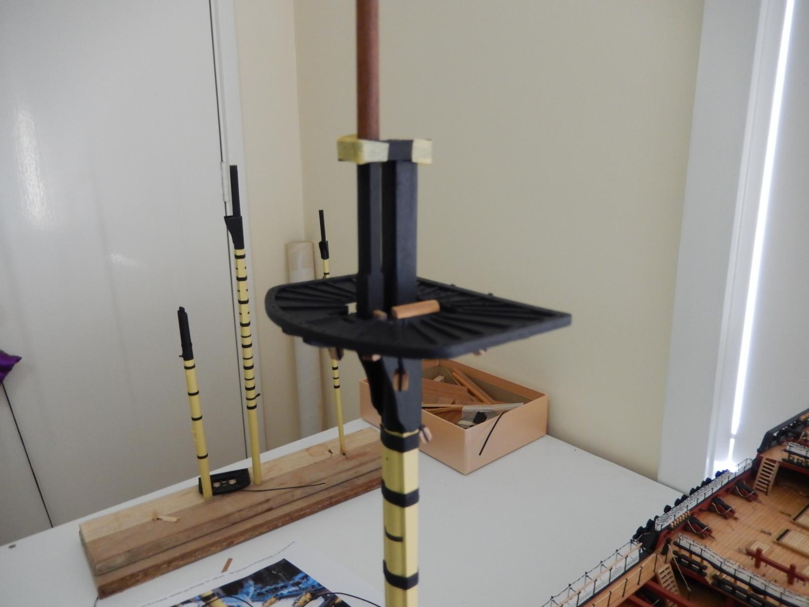
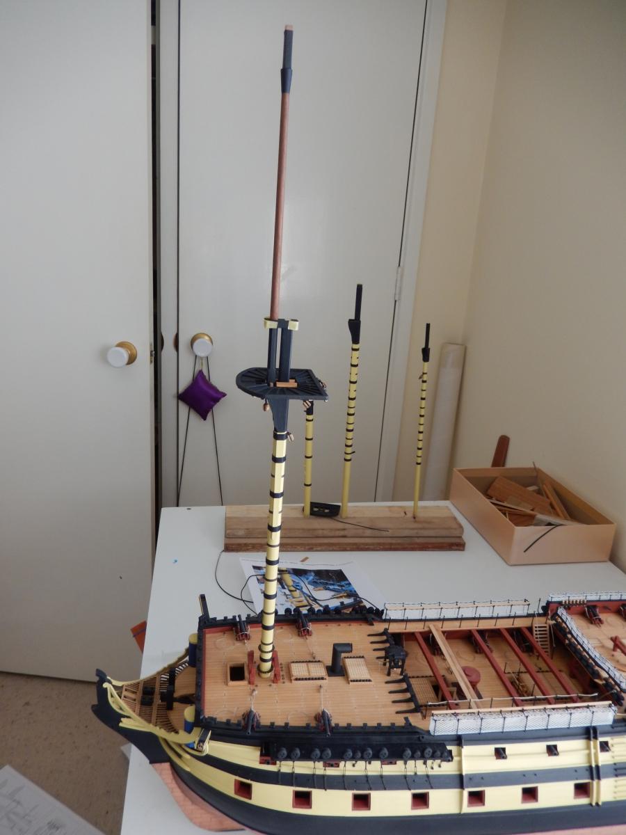
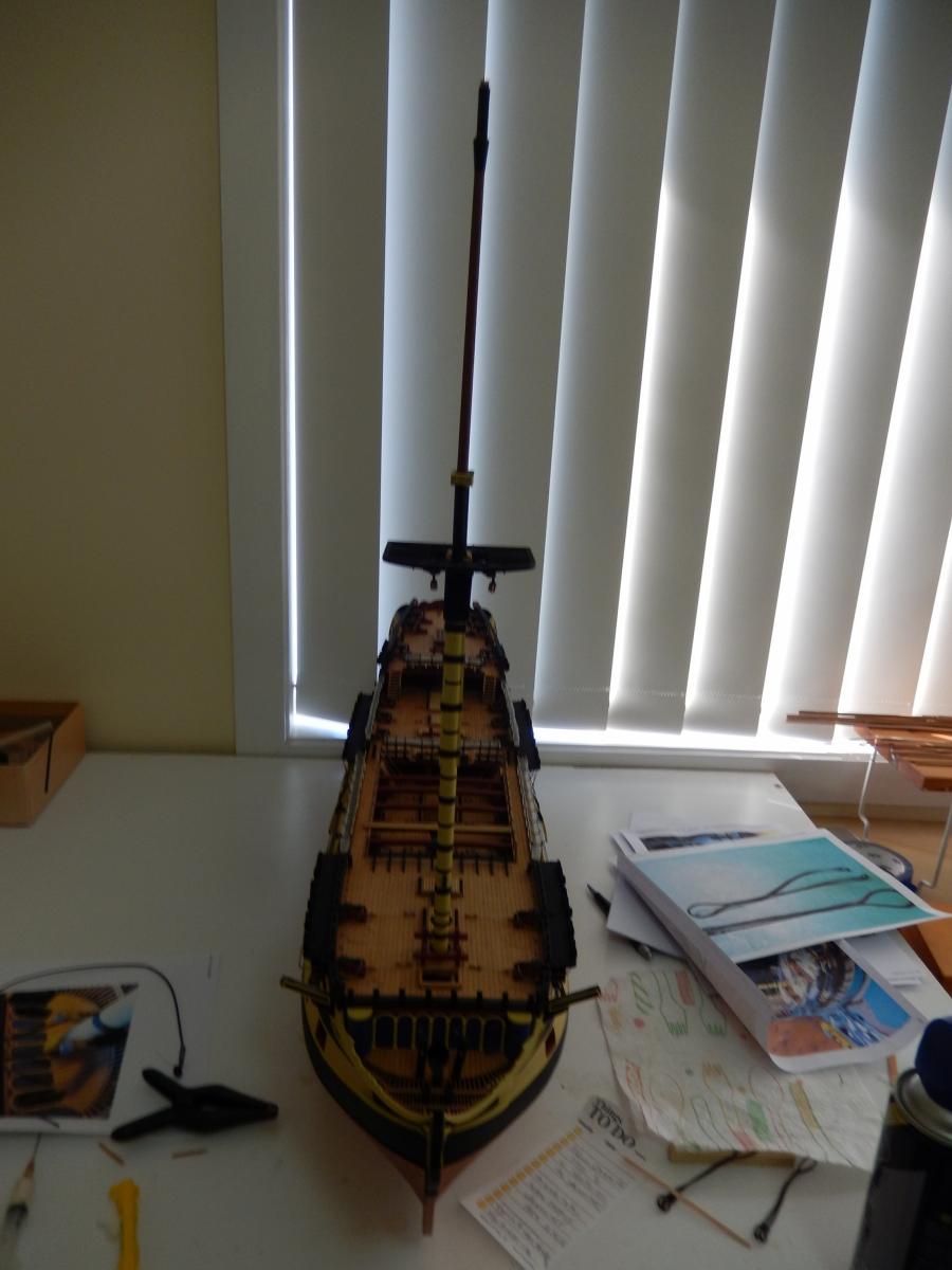
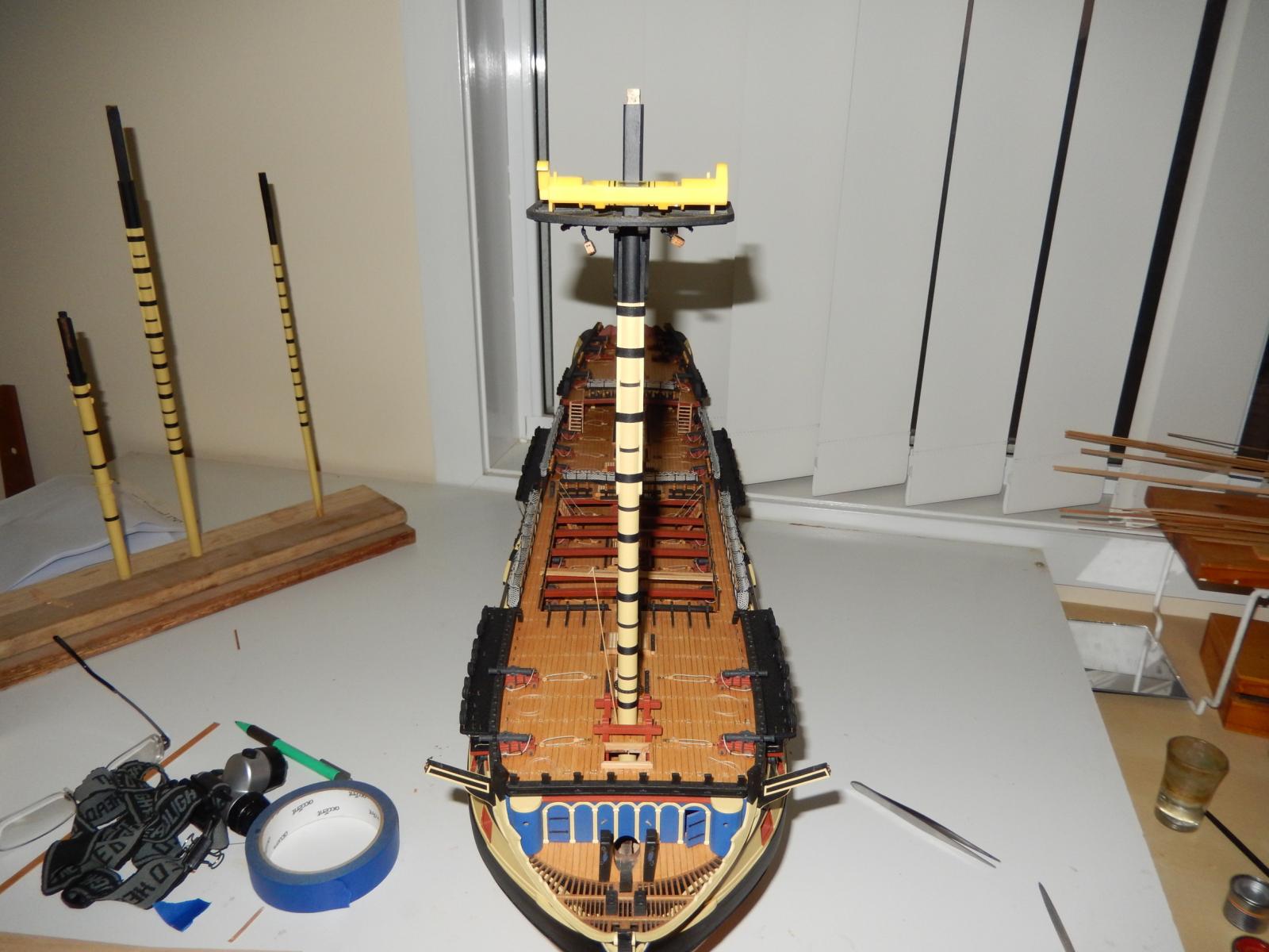
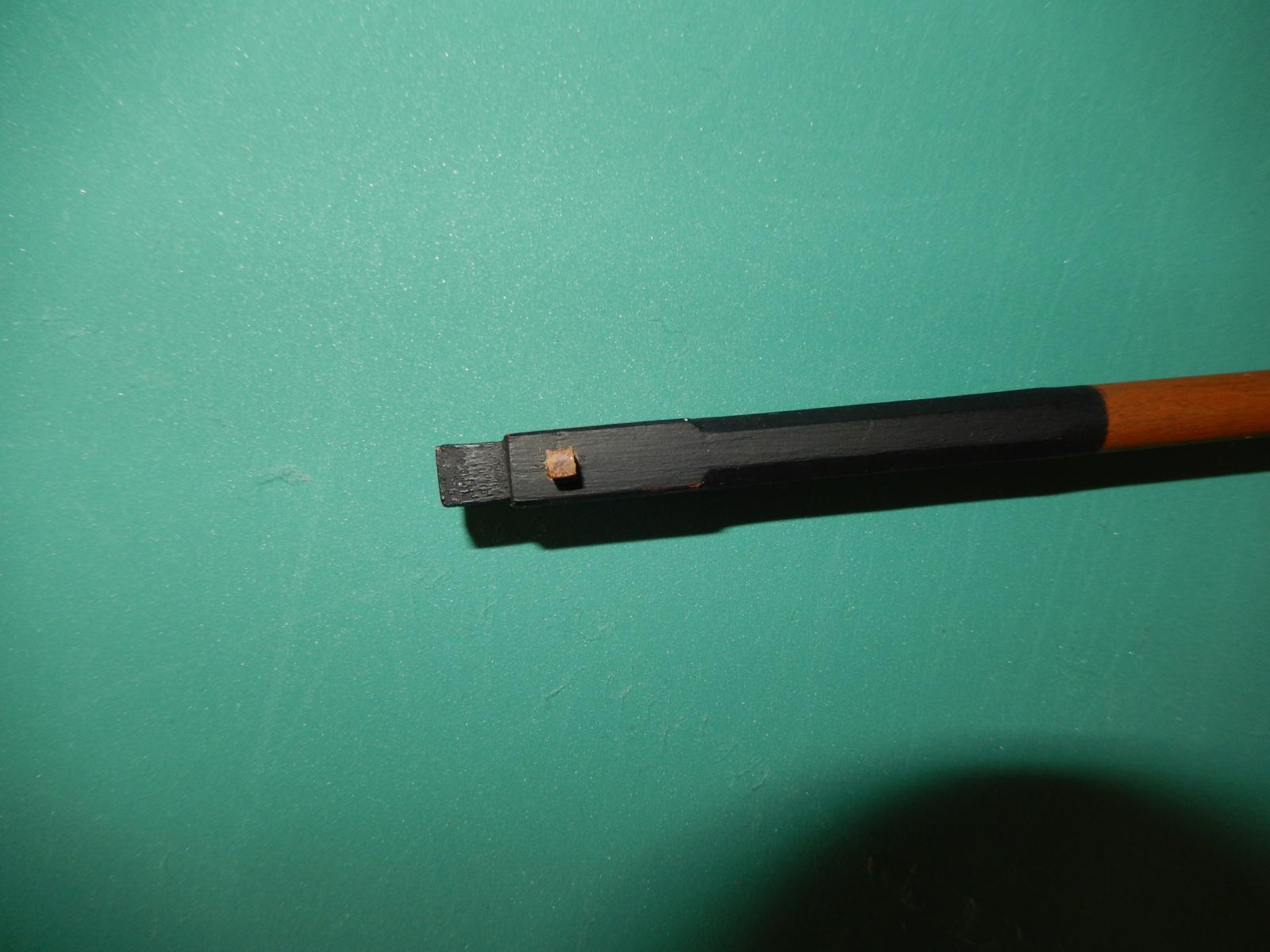
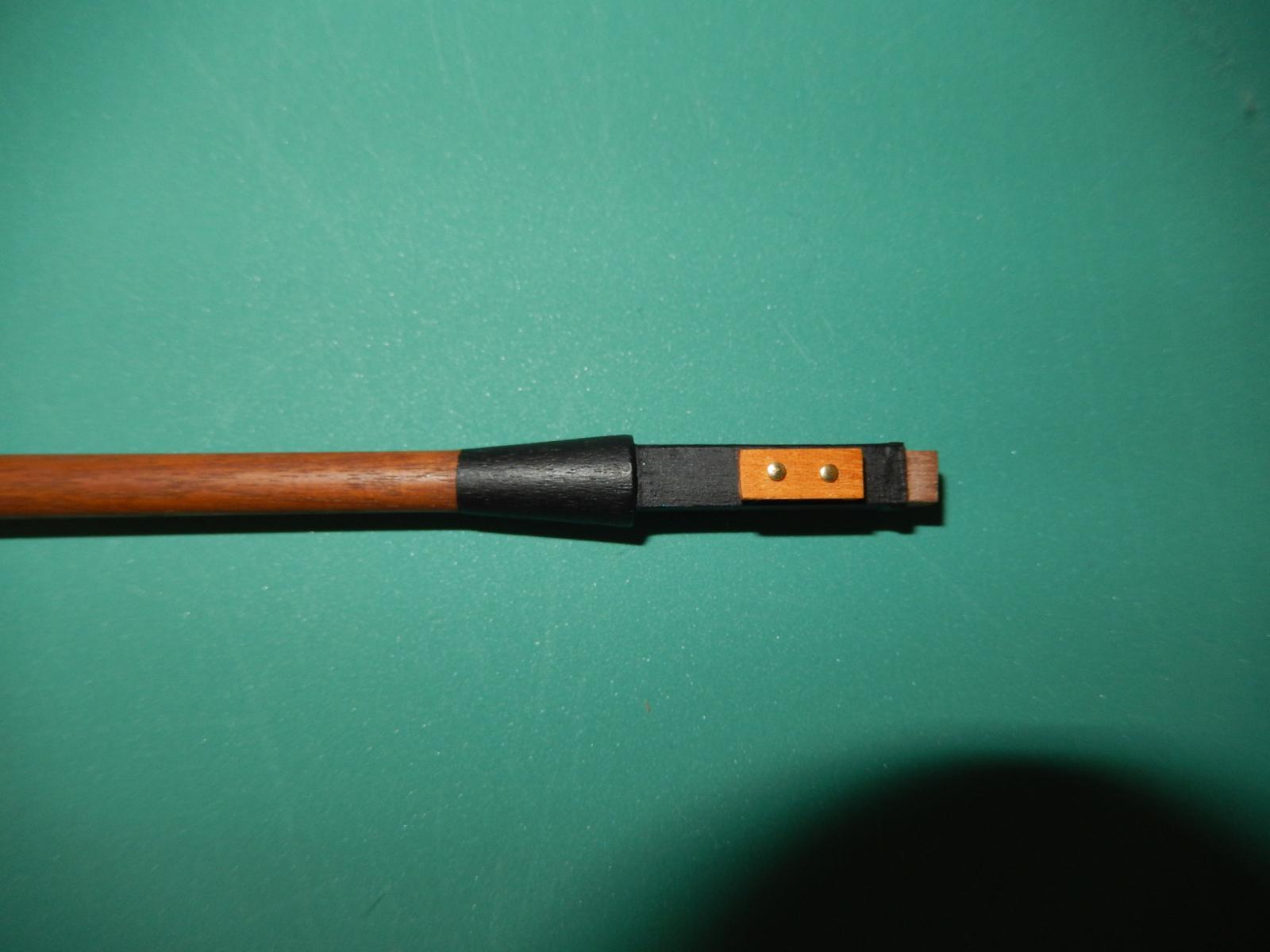
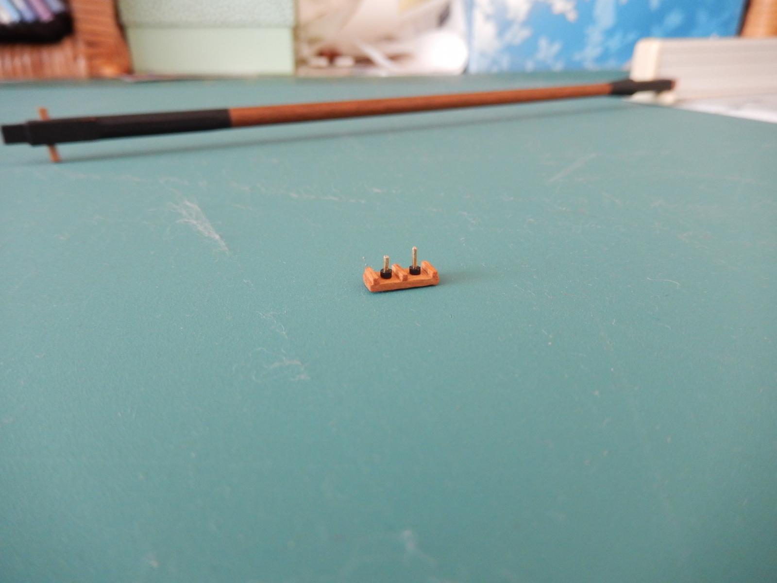
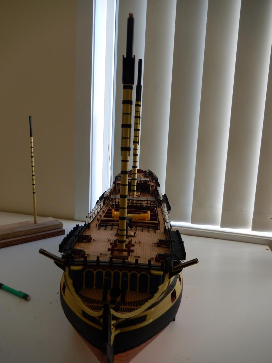
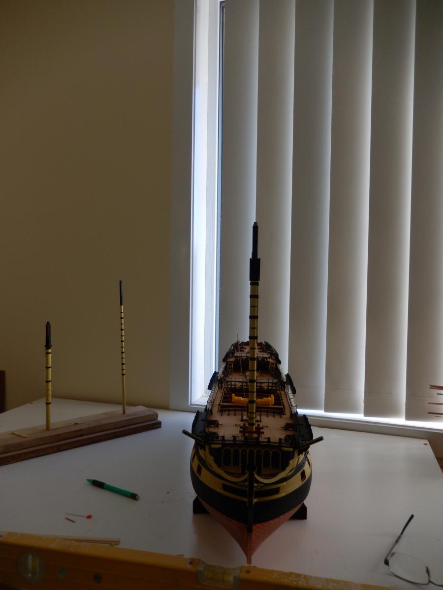
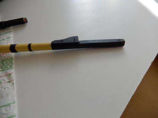
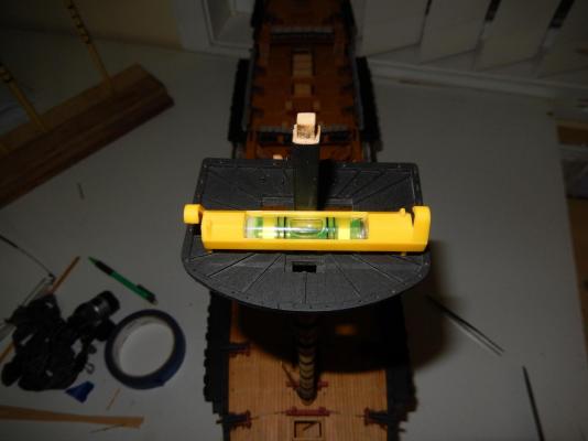
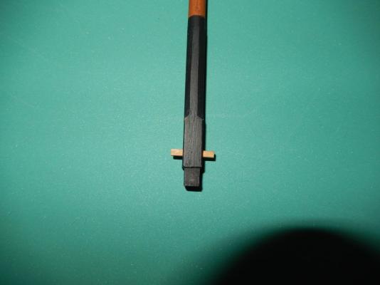
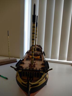
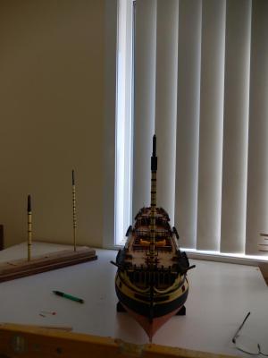
Work on the masts is slowly progressing. At this stage I am trying to make all the bits and pieces for the masts and where possible attaching them or providing for their attachment (eg: blocks, sheaves). Working on the masts after they have been stepped is not an attractive proposition. As I am sure that those familiar with Arthur's (AEW) log will see that I am not so much taking a leaf out of his book, but stealing his whole library. The top shown below is only dry-fitted as is the foremast. The photos are included only so that Alan (AON) can see that everything in the southern hemisphere is on the level. Here is the fid (dry-fitted - slight adjustment still to be done): square peg in square hole after much filing of round hole with square needle file. The sheaves for the fore topmast (dry-fitted), are now painted - and the following is shameless plagiarism.


-
Well I do know the table top is level (I put two different spirit levels all over it it), and I think the model is level (only one spirit level would fit) and I have hopes the blinds are vertical. Perhaps you can see where all of this is going - from more to less certainty. Just like life I guess ...
-
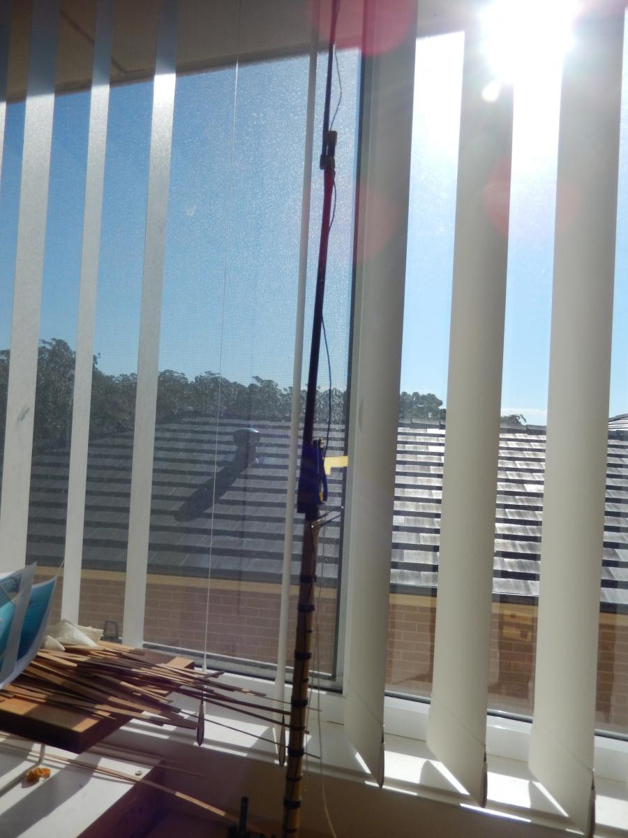
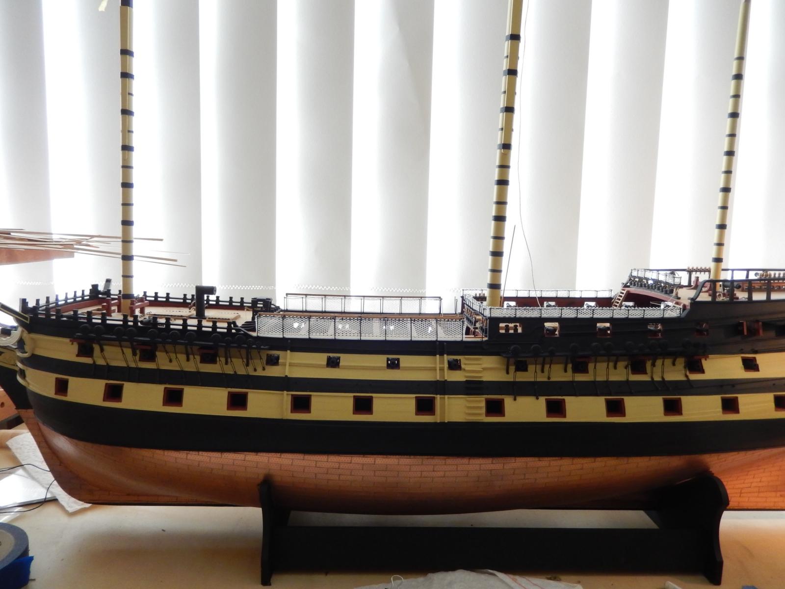
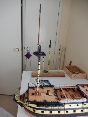
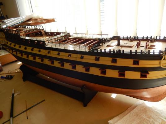
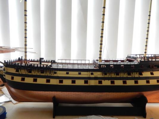
I am now starting the think about stepping the masts. Getting the masts vertical and at the correct (and consistent) rake is a concern. Then there is the problem in getting the tops properly horizontal and lined up fore and aft ..... At least I think I've solved one problem - getting the mast vertical. Hanging a plumb bob from the ceiling I suspect would not have made me popular with some around the house; being prone to disaster, moving the model to the rather spartan storage room under the house would have been risky. It then occurred to me that the vertical blinds in my work room are in fact (I hope) vertical and could be used as a plumb bob. Having checked that the top of my work table is horizontal (to my surprise it is) and making sure as I can be that the edges of model are horizontal, I then lined up the fore and main masts with the blinds. Here are the results, dry -fitted. When I pointed out the shear genius of all of this to my wife she gave me what I can only describe as a slightly pitying look, though of course it could have been a look of restrained admiration. Now all I have to do is solve for the other variables.
-
Arthur: Thanks for that. I'll see what I can do about making a similar table tomorrow. If I can figure out the middle row, I'll let you know. At the moment I'm looking for an excuse not to start the masts.
-
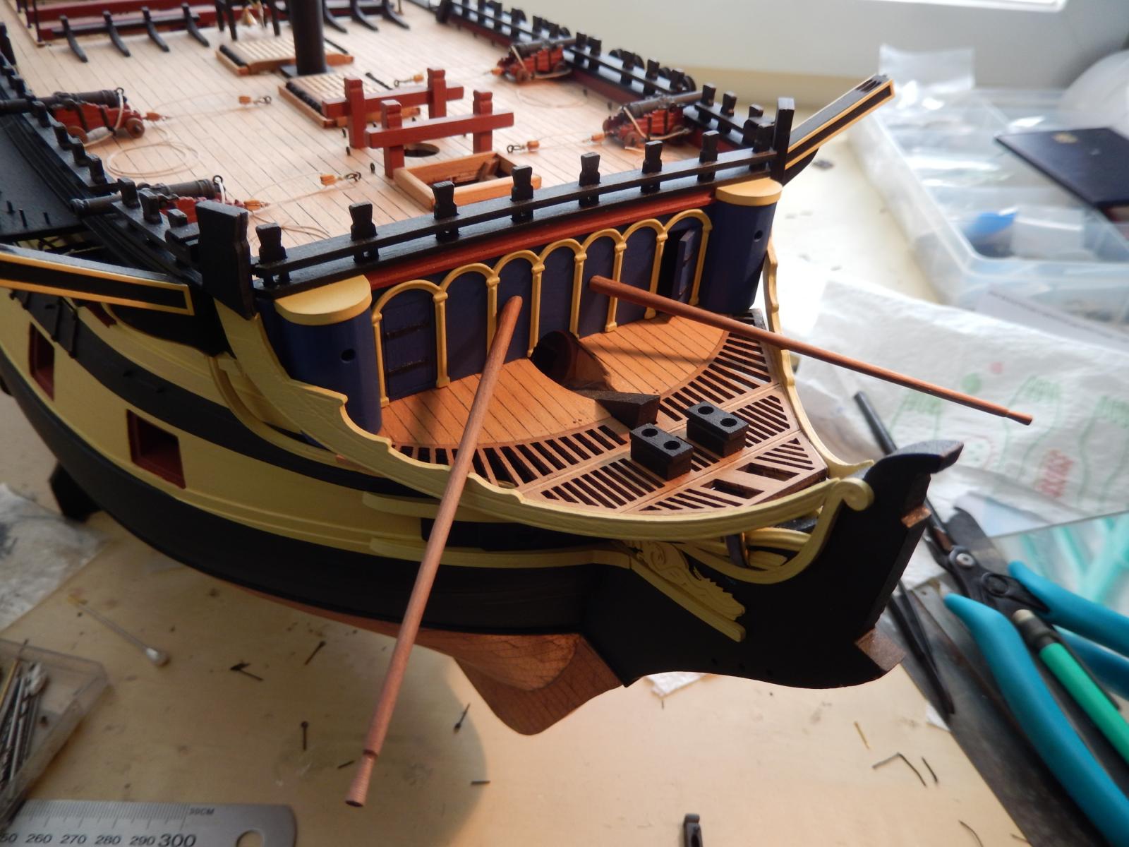
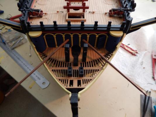
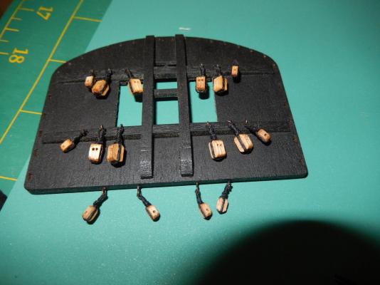
I have dry-fitted the boomskins will now paint them, and set them aside for as long as possible. Drilling the holes for the pins proved to be fairly easy. I began by drilling shallow holes at right angles to the bulkhead to prevent the drill bit from slipping, then drilled at an angle from the notch in the headrail upwards to the preliminary hole in the bulkhead. It worked without too many dramas. I guess the masts are next. Except for a bit of touching up the paint work, the masts are made up and ready to instal. The various fittings - blocks etc are yet to be completed. The blocks for the foretop are now fitted and I have now had the opportunity to use Alexey's serving machine. The blocks came out reasonably well, but I think I need some more practice and to put a bit more thought into just how to do a better job on the remaining blocks. My knot tying is not all that good.The machine certainly enabled me to do a better job and far easier than I otherwise could. Here are all the blocks fitted to the foretop. I found the plan to be not all that instructive. Fortunately I remembered that Arthur (AEW) has a photo of his foretop which cleared up a few of my doubts.


-
Arthur:The instructions say about halfway up the forecast bulkhead and about 10mm apart. If you look at the plan they are about 40mm apart at the bulkhead. The difficulty foresee is drilling holes for the pins in the bulkhead at the correct angle without messing up the paintwork, though this may turn out to be quite easy. (I find pessimism as a default to be the best, then sometimes you're pleasantly surprised.) There does appear to be a notch to receive the boomkins in the head rails but I haven't yet made them up to test it. I'll have a play tomorrow to see how it goes - but I certainly won't fit them at this stage.
-
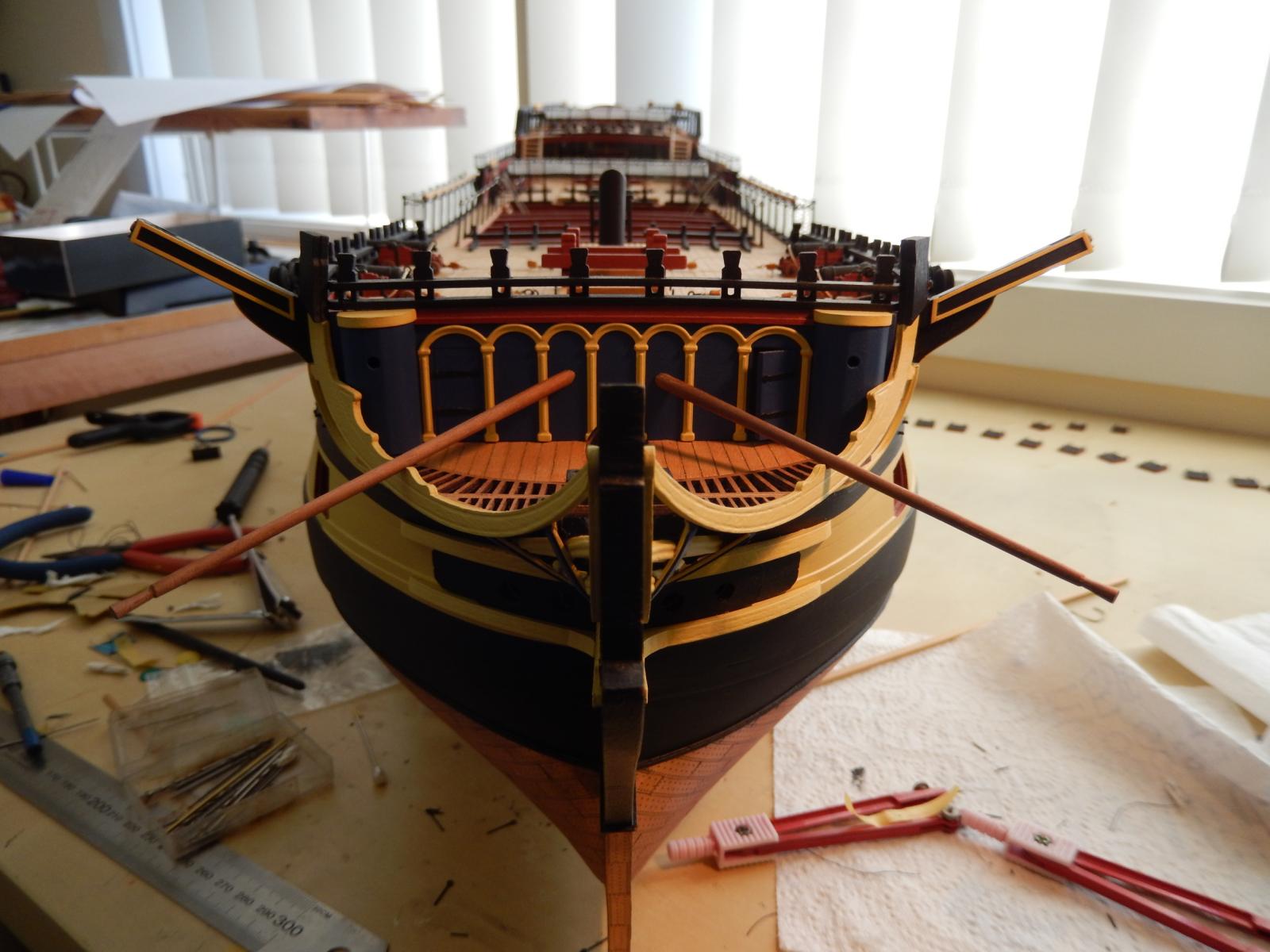
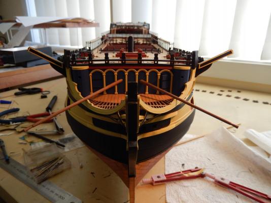
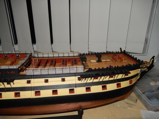
I have now (semi) finished the right side of the model while contemplating Alan's thoughtful remark. I decided that any response would only end in (my) tears. The stern-most channel did provide some problems. The rear-most vertically hinged doors again needed to be fudged a little, and for no good reason, I had quite a bit of trouble getting all those doors to sit vertically. It all seemed to come out reasonably in the end though. While thinking about what to do next, I resorted to that final resort - the instructions. These then specified that 'boomkins' be added. Not having a clue just what a boomkin is I then went to the final, final resort - wikkepedia - where a very nice picture of the 'Surprise' may be found, boomkin and all. I then looked at the main plan and indeed, there are boomkins. I certainly would have overlooked them until they were quite difficult to install. Even now it will be awkward, and once I make the pair up, I will only dry-fit them as they are other things that stick out the side, asking for trouble. Here are photos of the stern-most channel etc And how it all looks:


-
Thanks Keith. I passed on your kind comment to my wife but all she did but laugh. Perhaps she misunderstood .... Bob
-
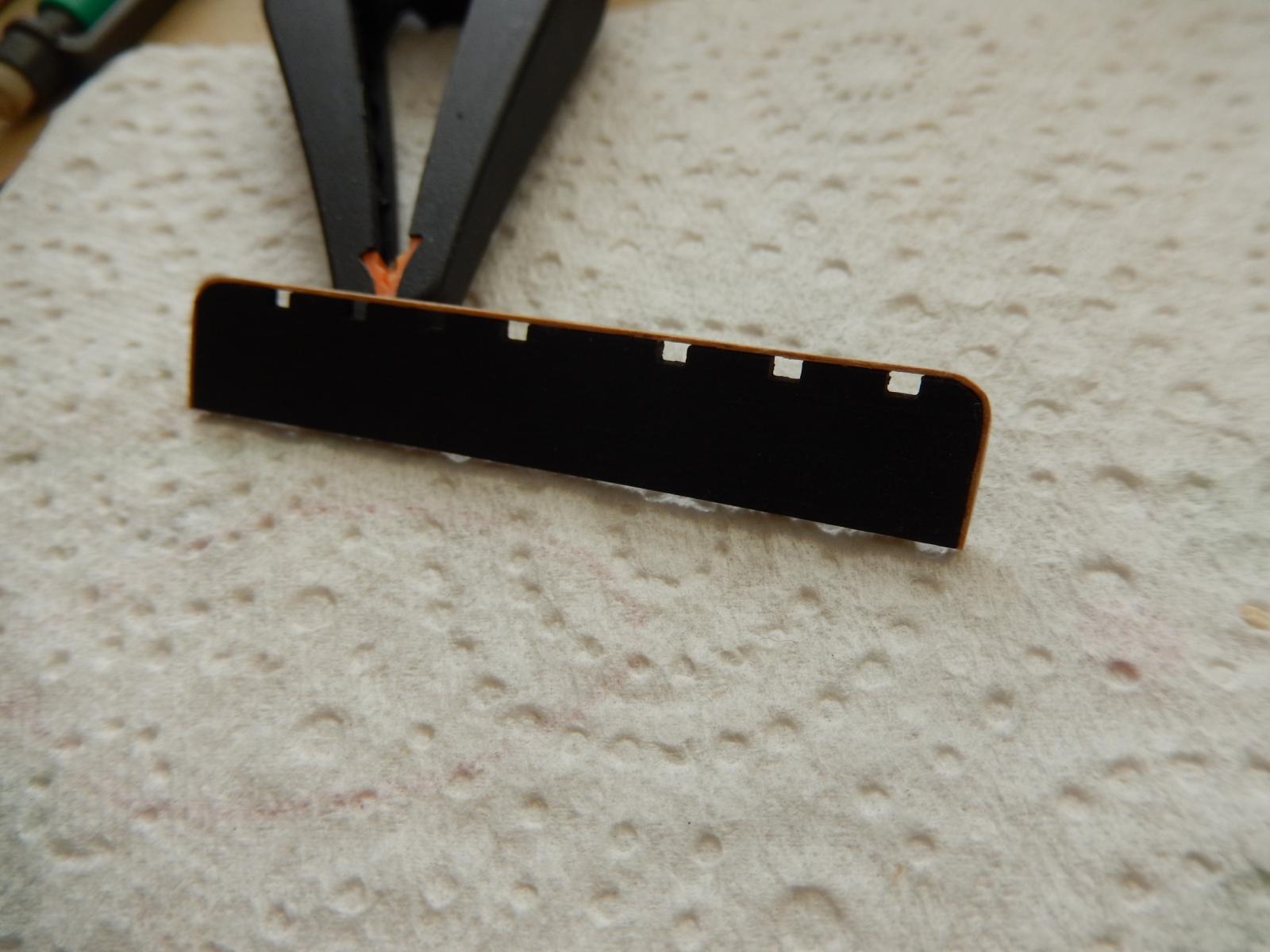
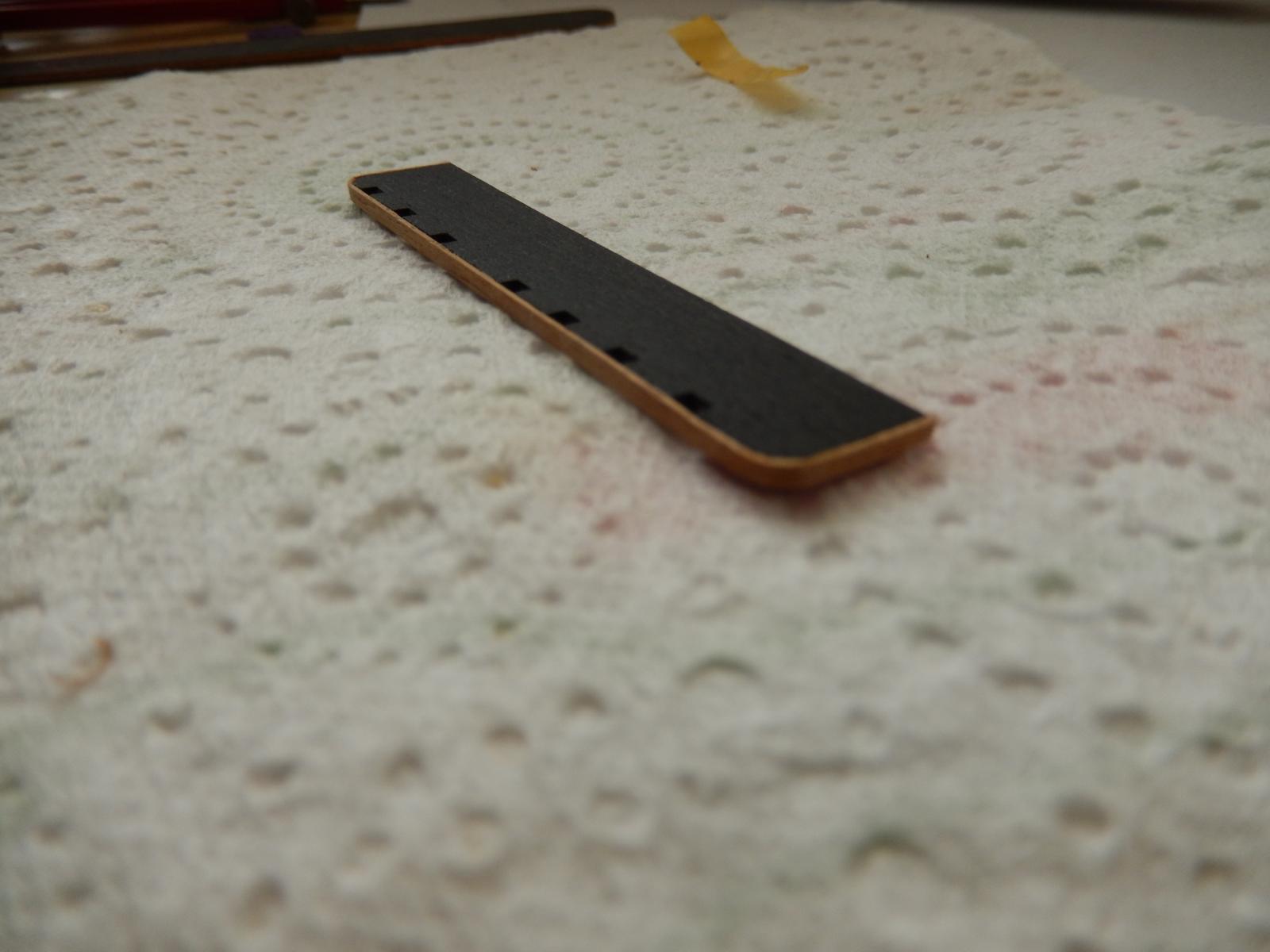
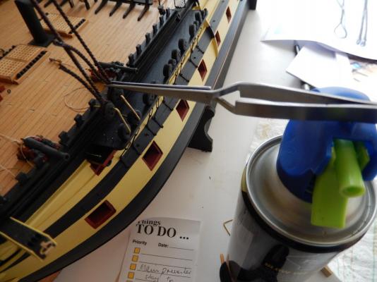
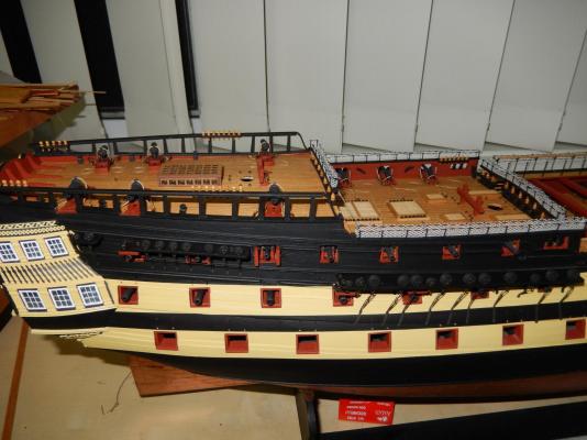
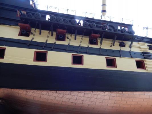
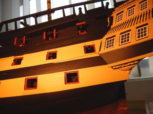
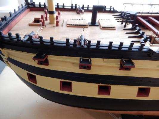
The channels and chain plates on the right side are now almost complete. The fore and mid channels are finished, while the stern-most will have the chain plates applied in the next day or so. The lower gun port lids have been dry-fitted. Here are some views of the fore channel. There is still a bit of touching up to do . Here is the mid channel. The result so far has been acceptable enough and has not been as formidable a job as I anticipated. - though there have been a couple of thrills along the way. Perhaps I shouldn't get too far ahead of myself as the stern chain plates are still to be completed.


-
Thank you for the encouragement Ronjja. I am now in the process of taking the right hand side of the model to the same stage as the left. I should be there in a week or so.
-
Thanks for the kind comment Jason, and to those 'likes'. (Incidentally, do you have to be on facebook to 'like' something? I'm afraid all that stuff has by-passed me. ) Bob
-
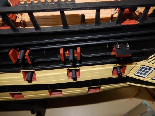
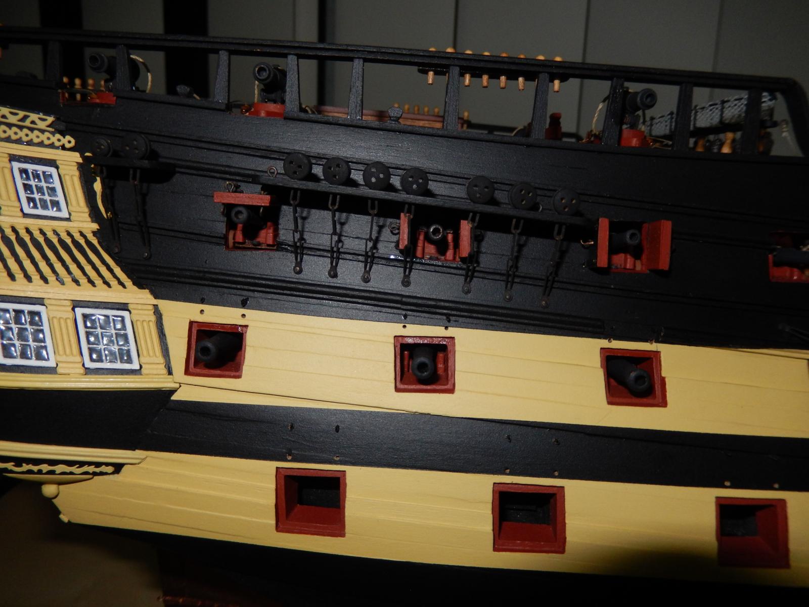
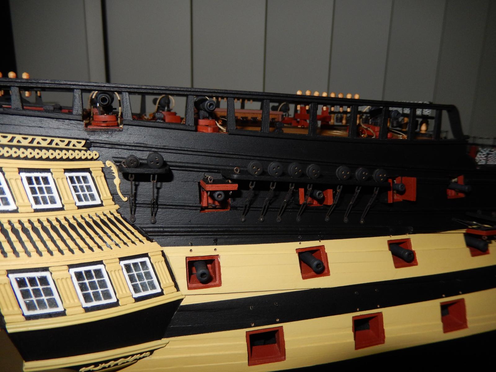
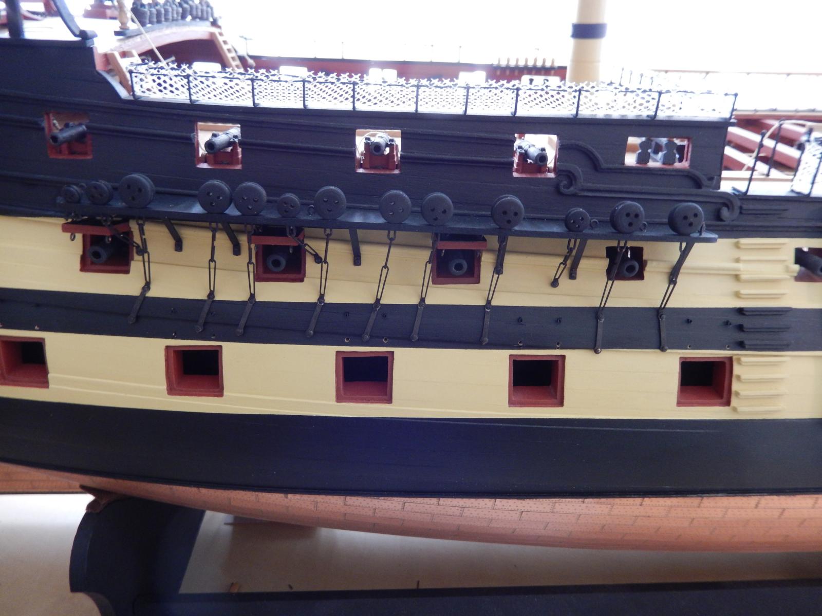
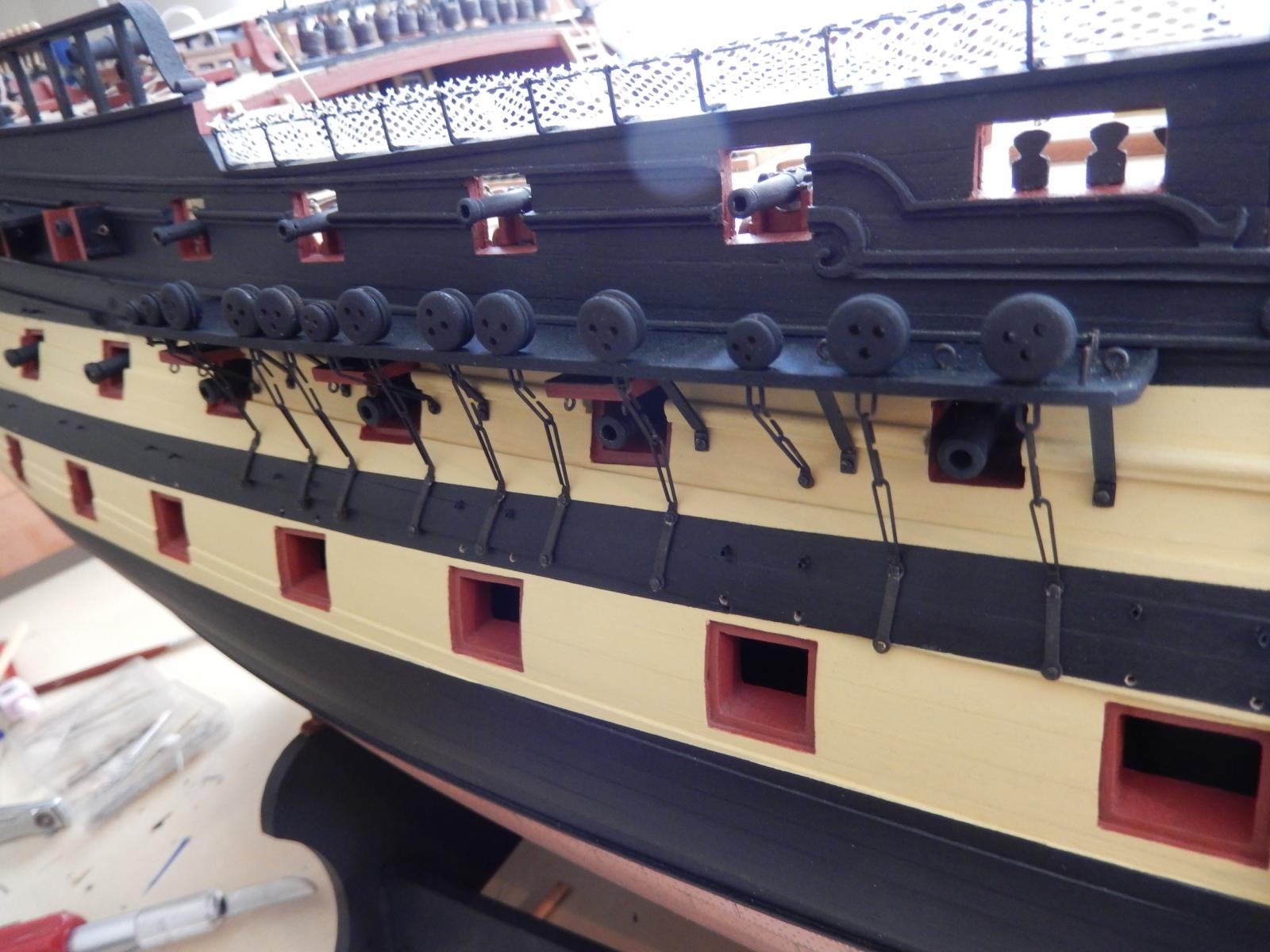
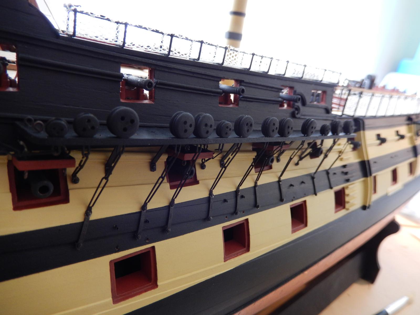
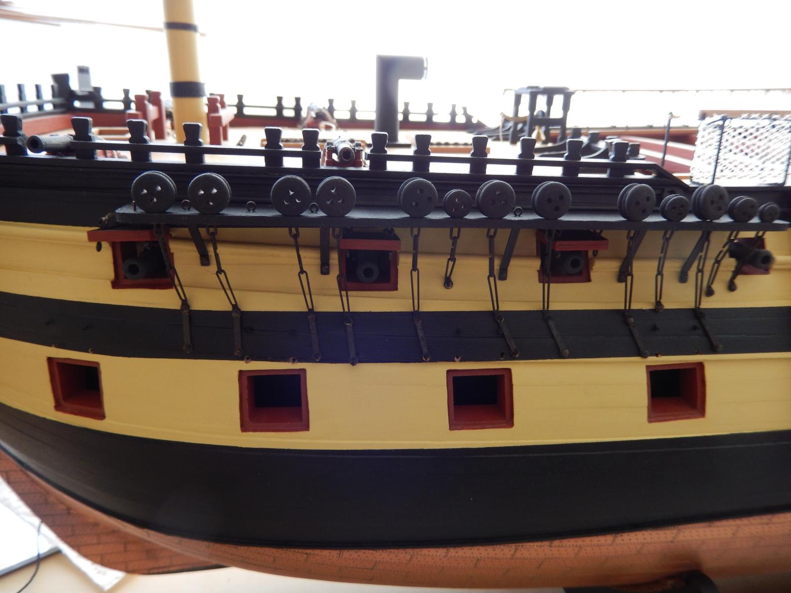
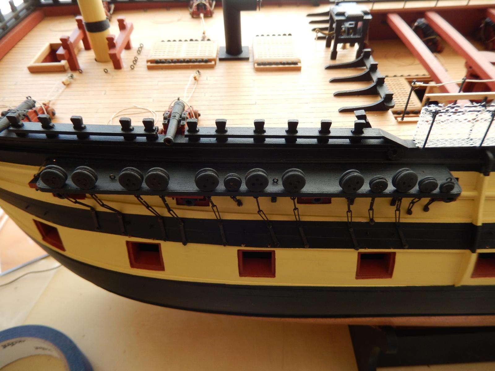
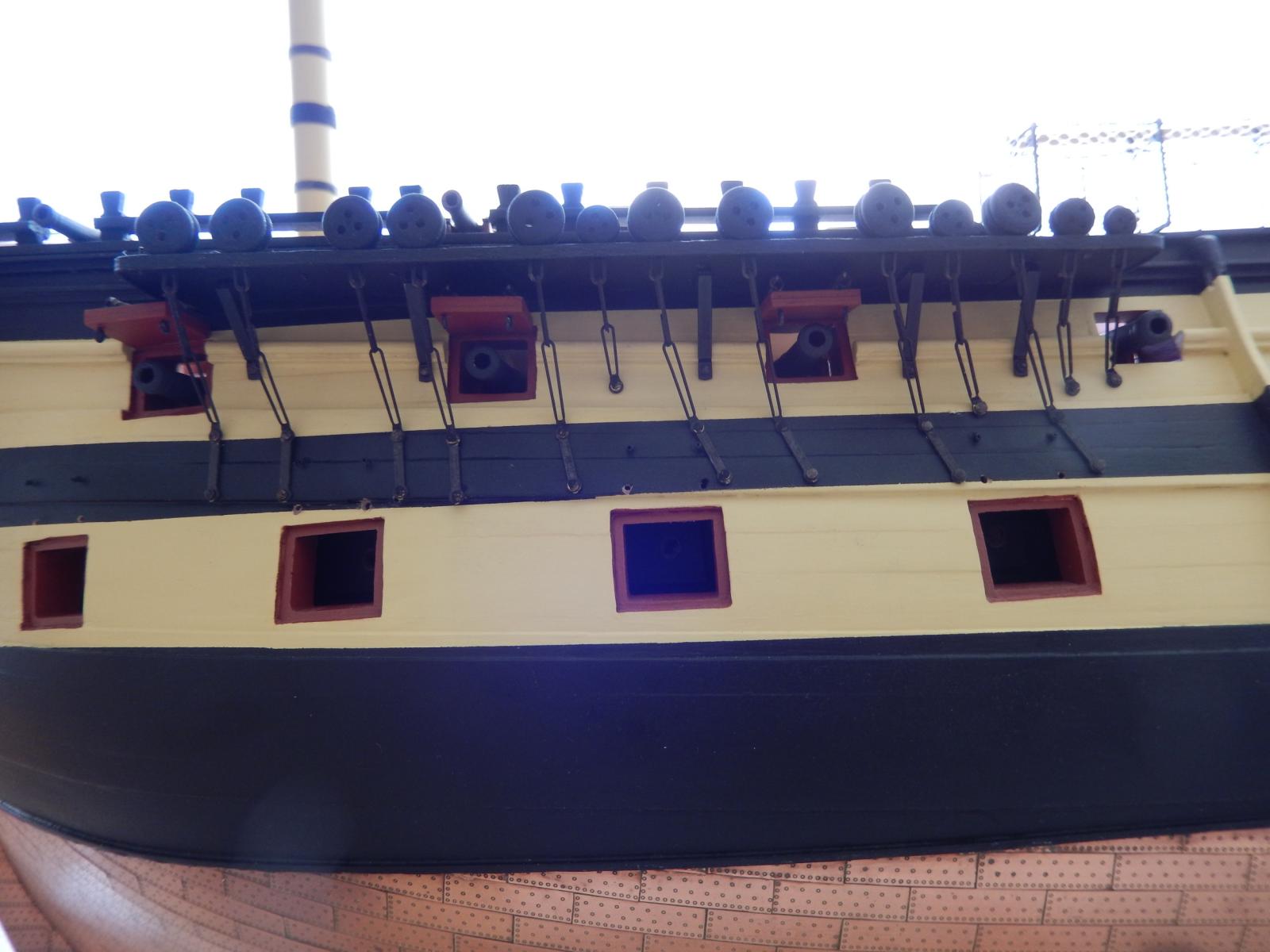
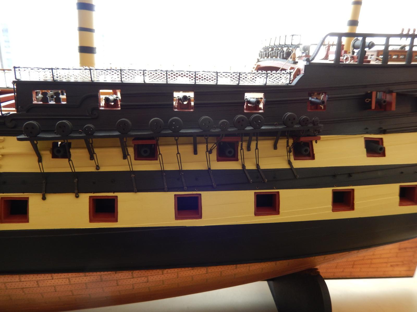
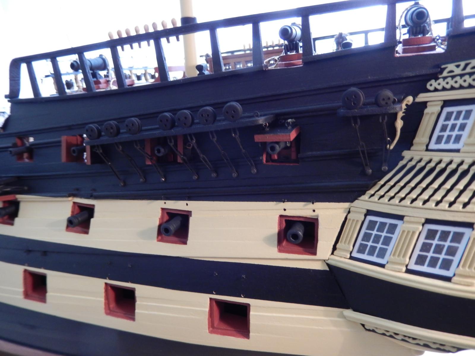
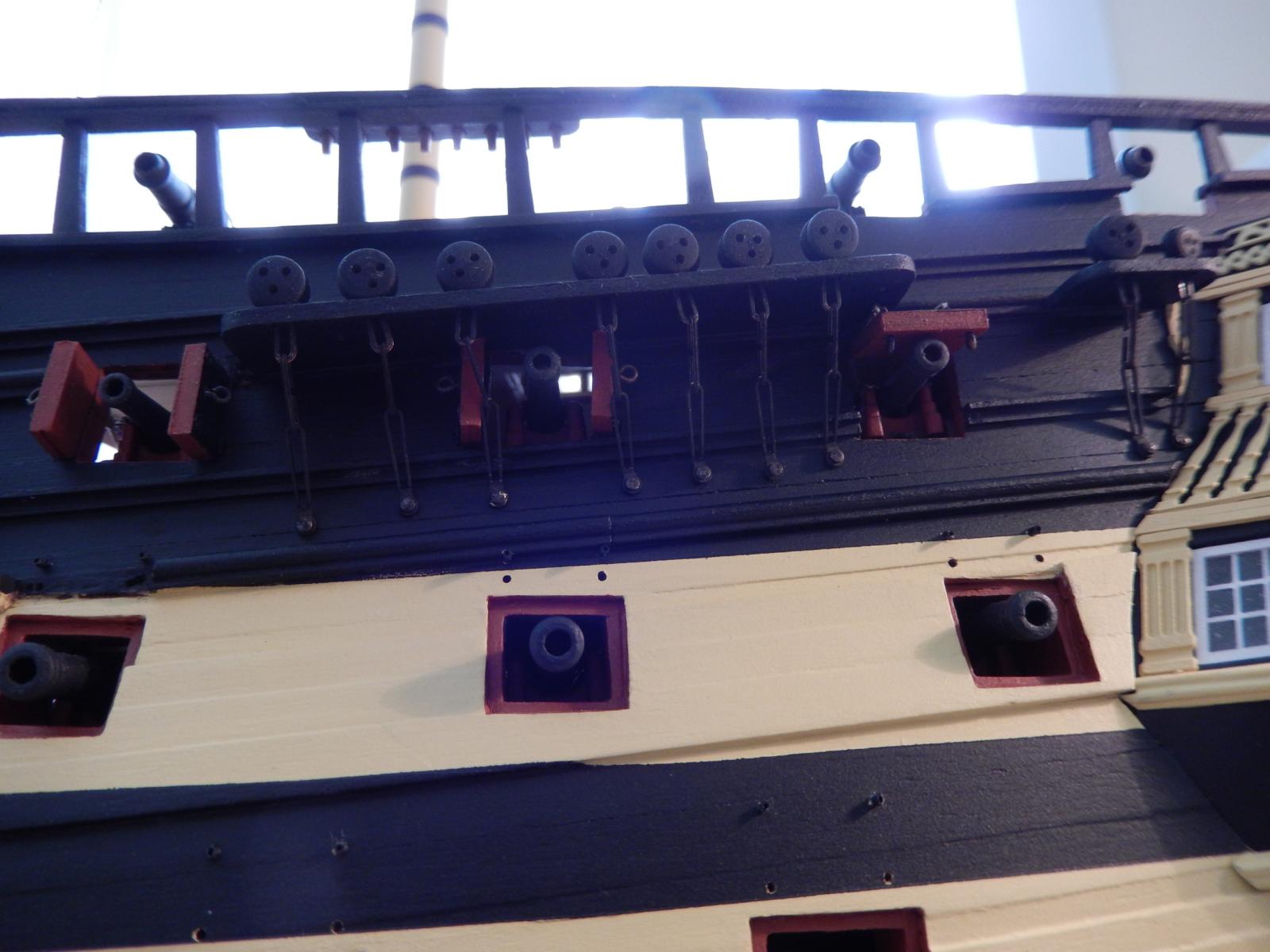
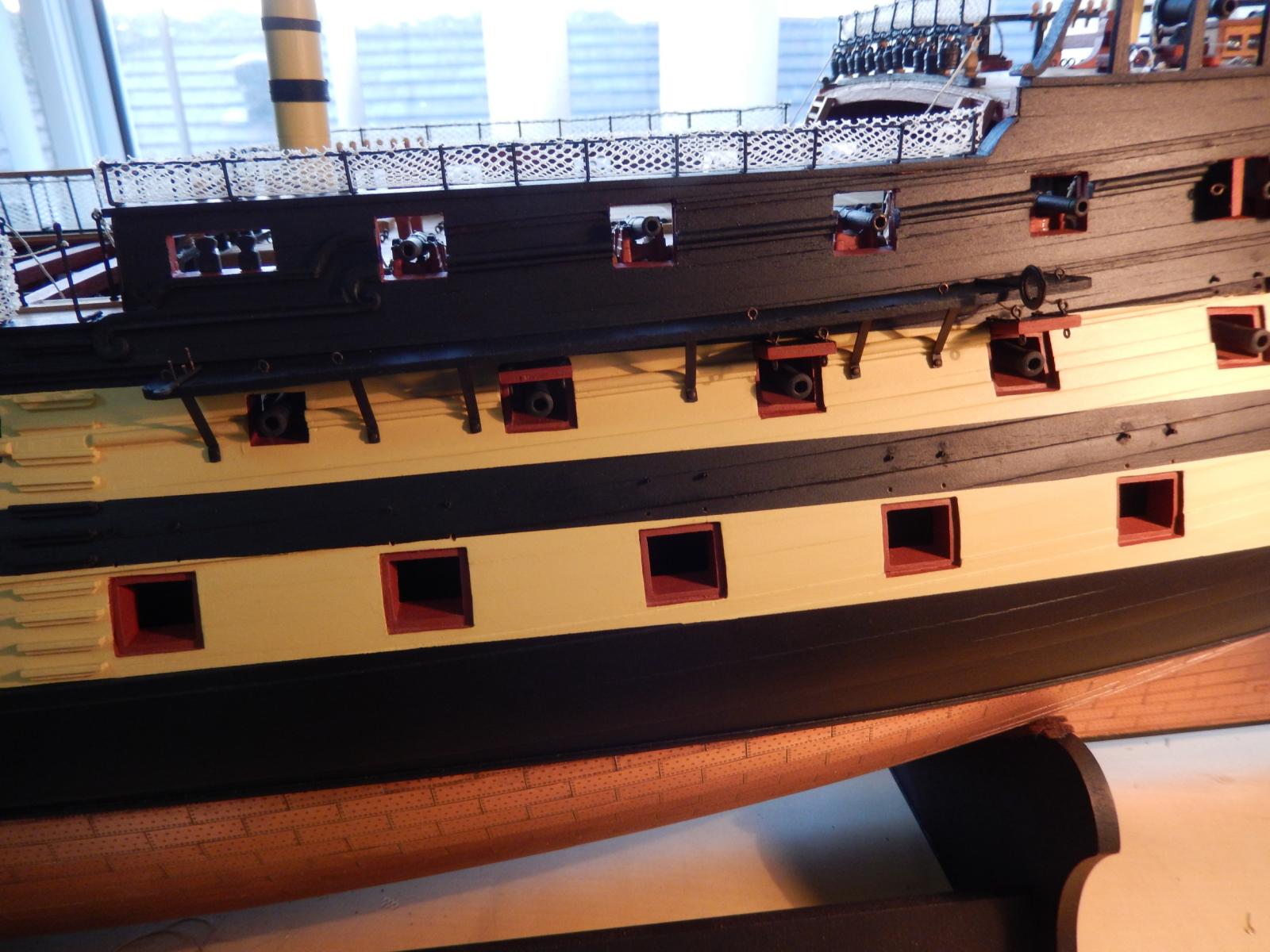
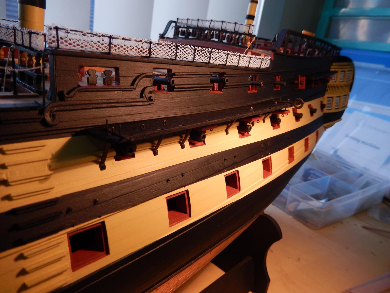
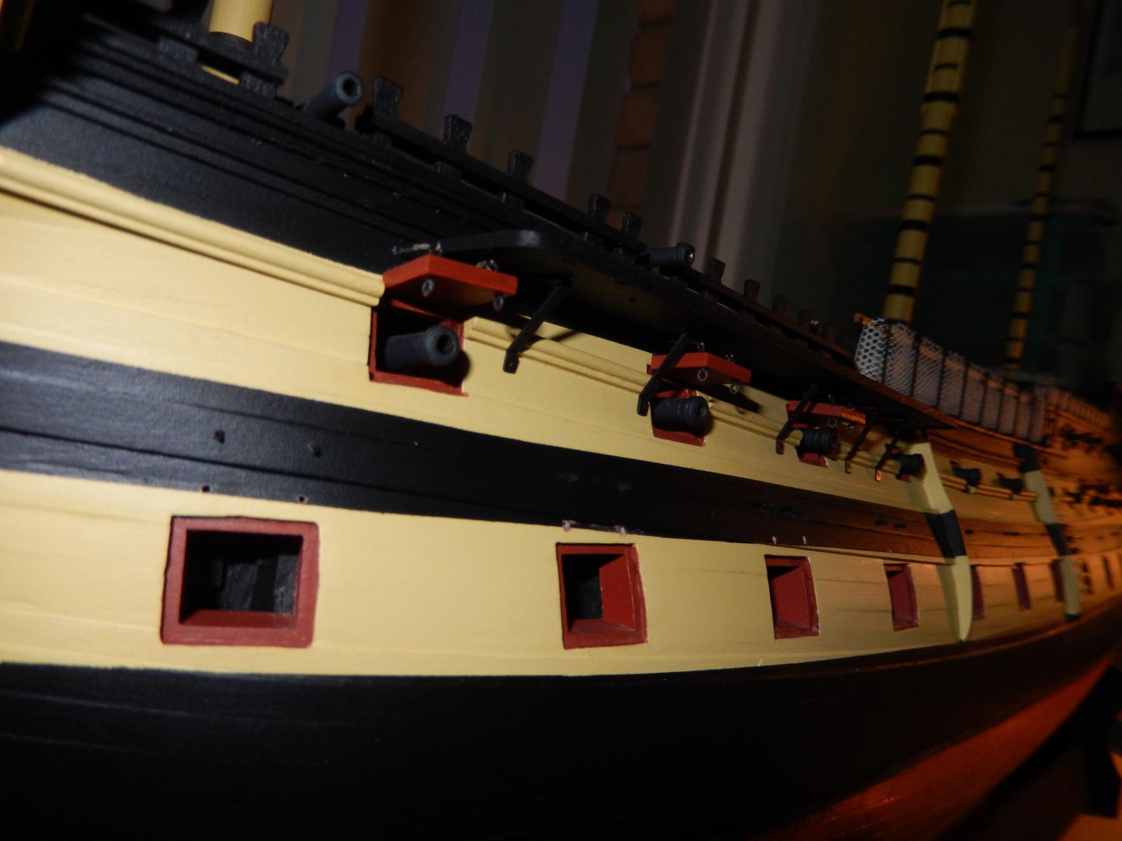
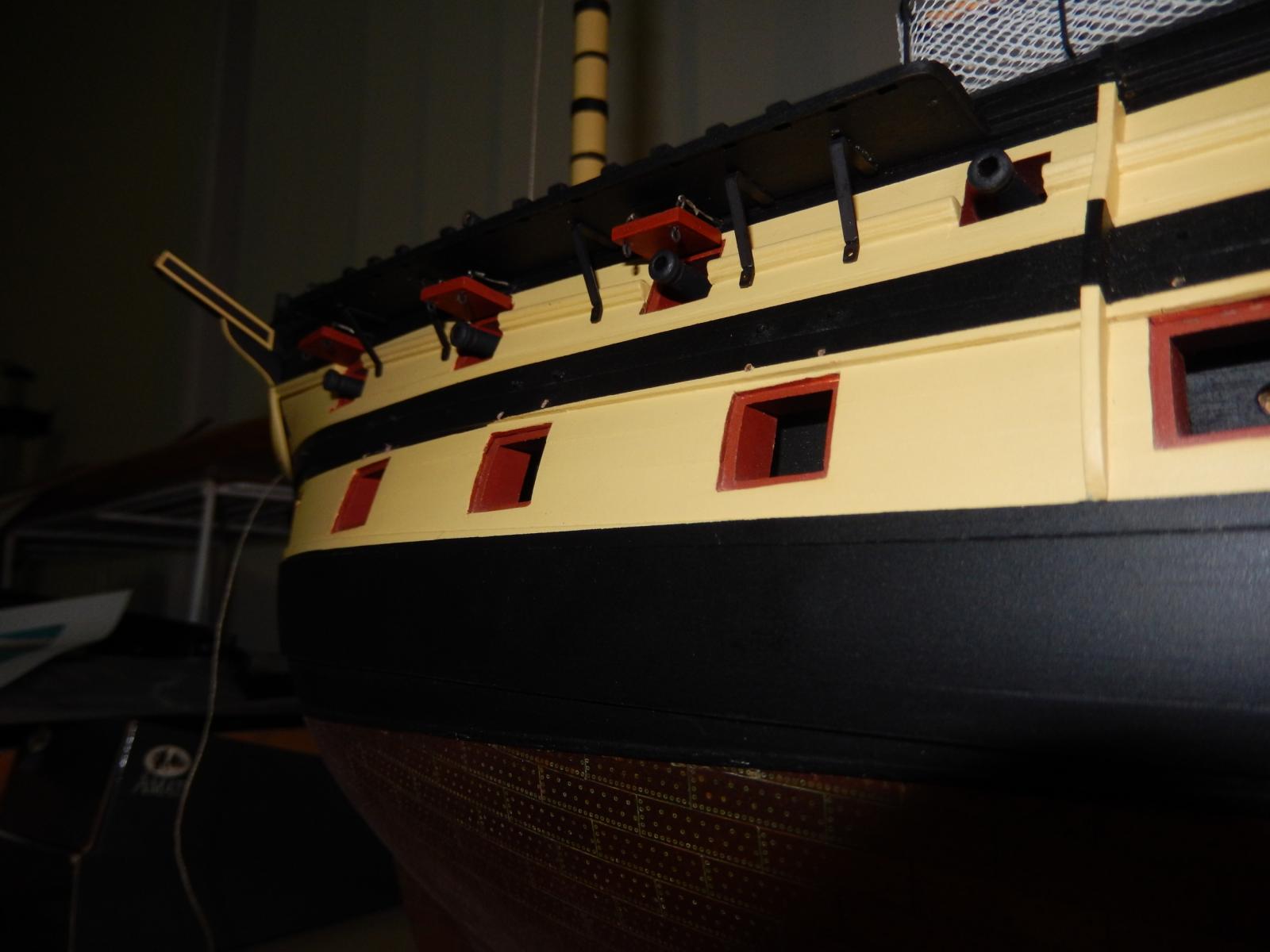
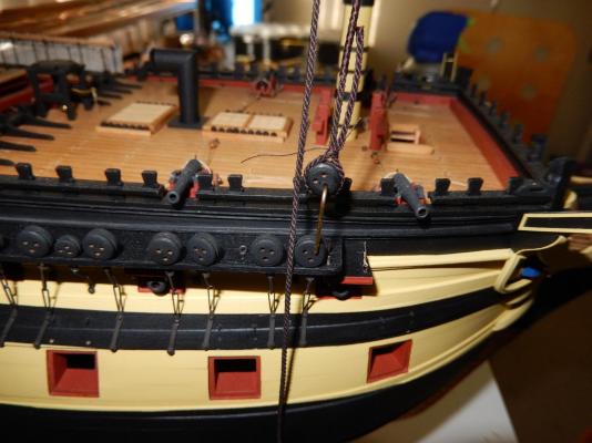
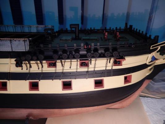
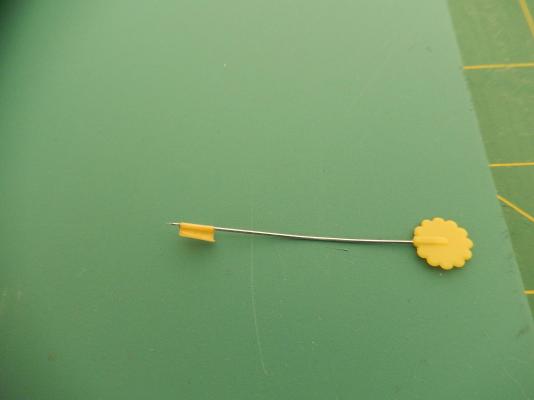
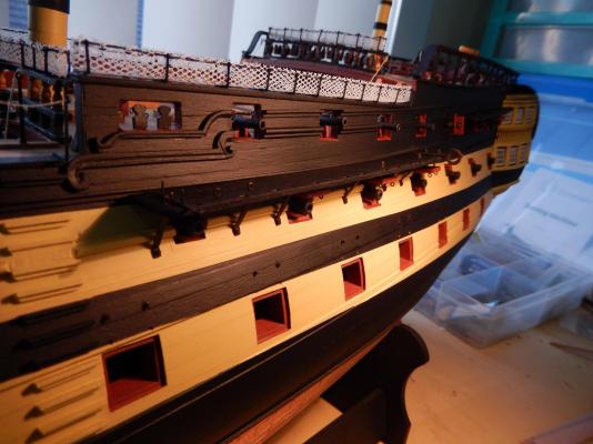
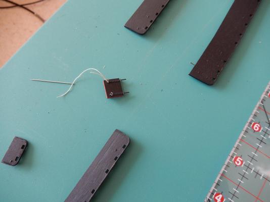
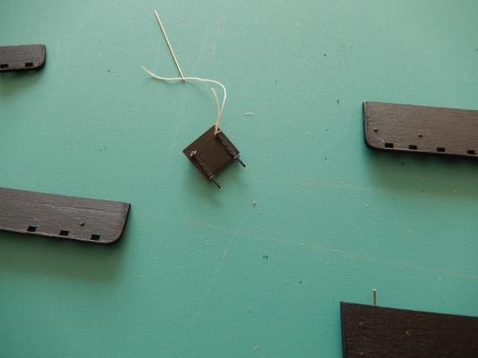
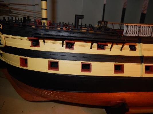
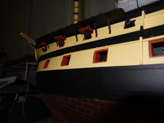
The left side of the model is as complete as I think is prudent at this stage of construction. The fewer bits and pieces to catch on something the better. The deadeyes and chainplates are now installed. I am reasonably happy with the way they turned out, though with hindsight there a few things that I would do a little differently. For each of the deadeye assemblies I ran a piece of thread from the respective points on the masts to which the shrouds are attached down to each deadeye. In effect this is a dummy shroud. This gives the angle of the chainplate assembly for each deadeye. The following photo shows the thread attached to one of the upper masts. These were temporarily attached with Tamiya tape. I then took a pinand wrapped some tape close to the point. The pin was then placed in the hole provided in the chain plate strap to mark the hull ready for the hole to be drilled for the nail. The tape on the point of the pin prevented the stray riding up the pin. Here is how it all worked out. The foremast deadeyes. The main mast. The tiny deadeye at the very end provided a real problem. There was simply not enough room for the chainplate assembly to go where the plan said it should. As well the assembly as specified was too short to attach to the hull. I ended up using one of the longer straps and attached it to the hull in the only place it would reach without fouling thegun port lid. I have tried to show it in the following photos. I don't think it is too obvious, but it rankles a bit. I would also have preferred the the securing straps on the two front assemblies not go below the black stripe. Had I thought of it, I would have at least tried the shorter straps for these. Oh, well ... The mizzen. The third assembly just touches the left vertically hinged gun door which would make it rather difficult to close. I guess the crew will have to learn to live with it open. Finally, this is how it all looks at the moment.


- 949 replies
-
- 11
-

-
That all makes sense. I do have a copy of Petersson, but it didn't occur to me to look at this. I'll certainly take your advice. Oddly enough I too have built an Astrolabe. I see you've done a wonderful job on yours. I revised a lot of the rigging on that model consistent with Petersson' book. Thanks .... again
-
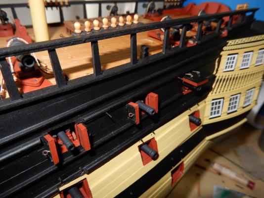
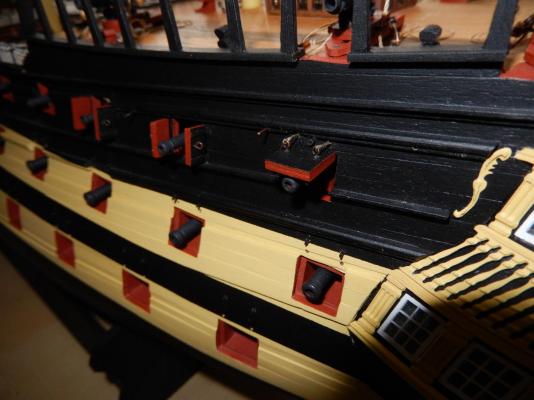
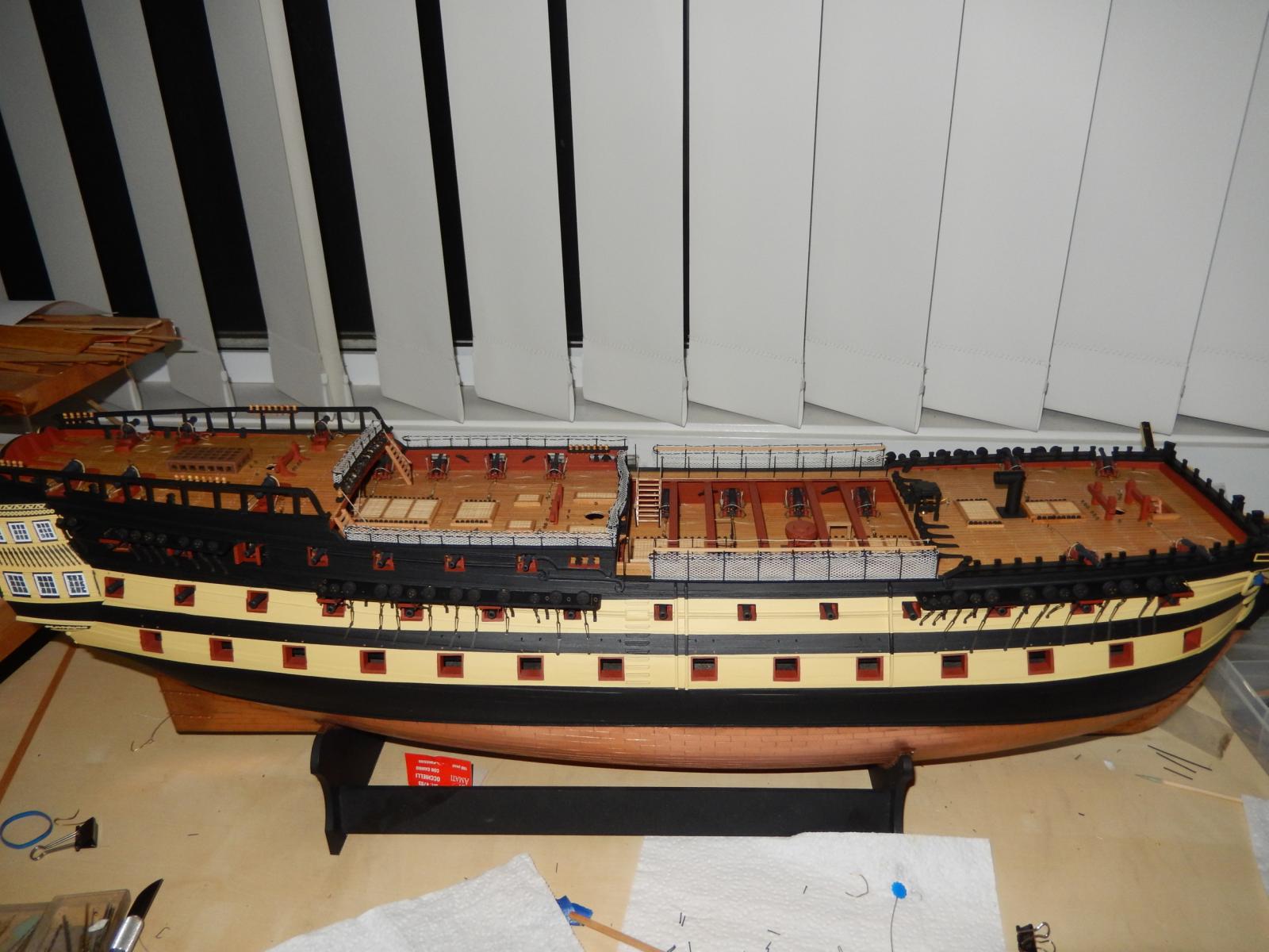
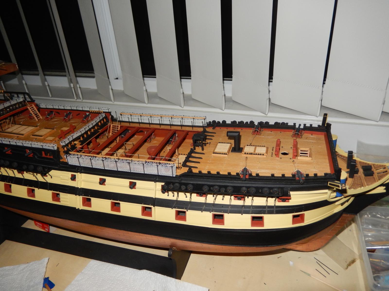
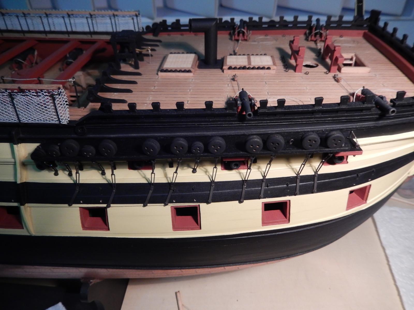
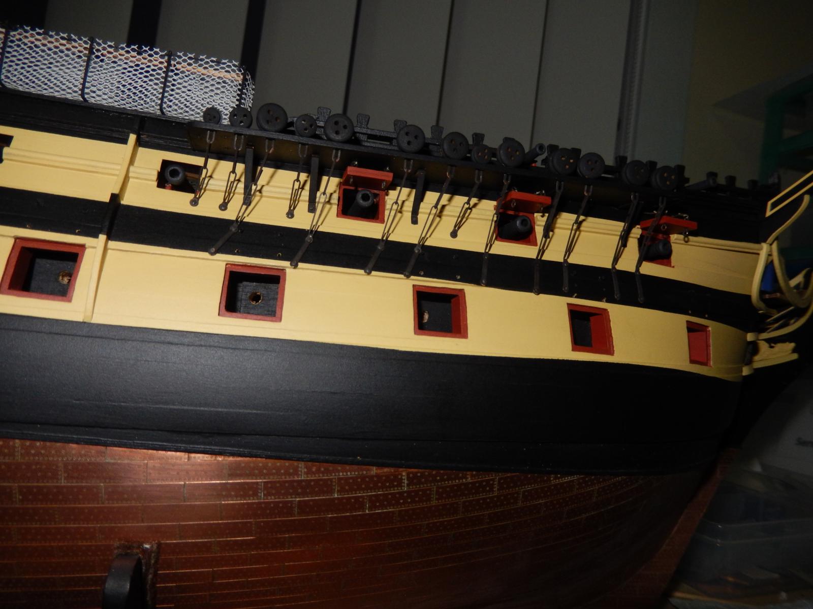
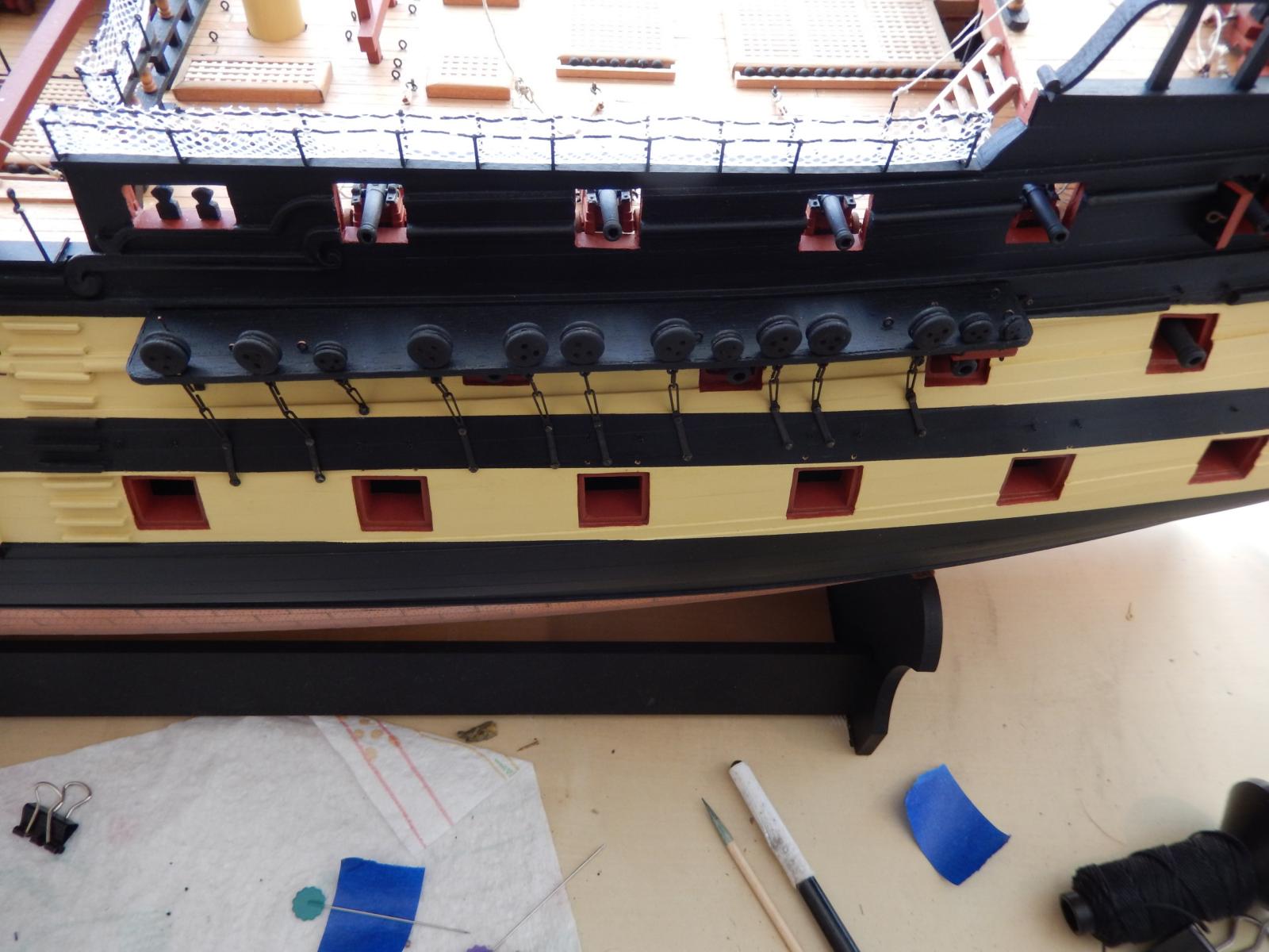
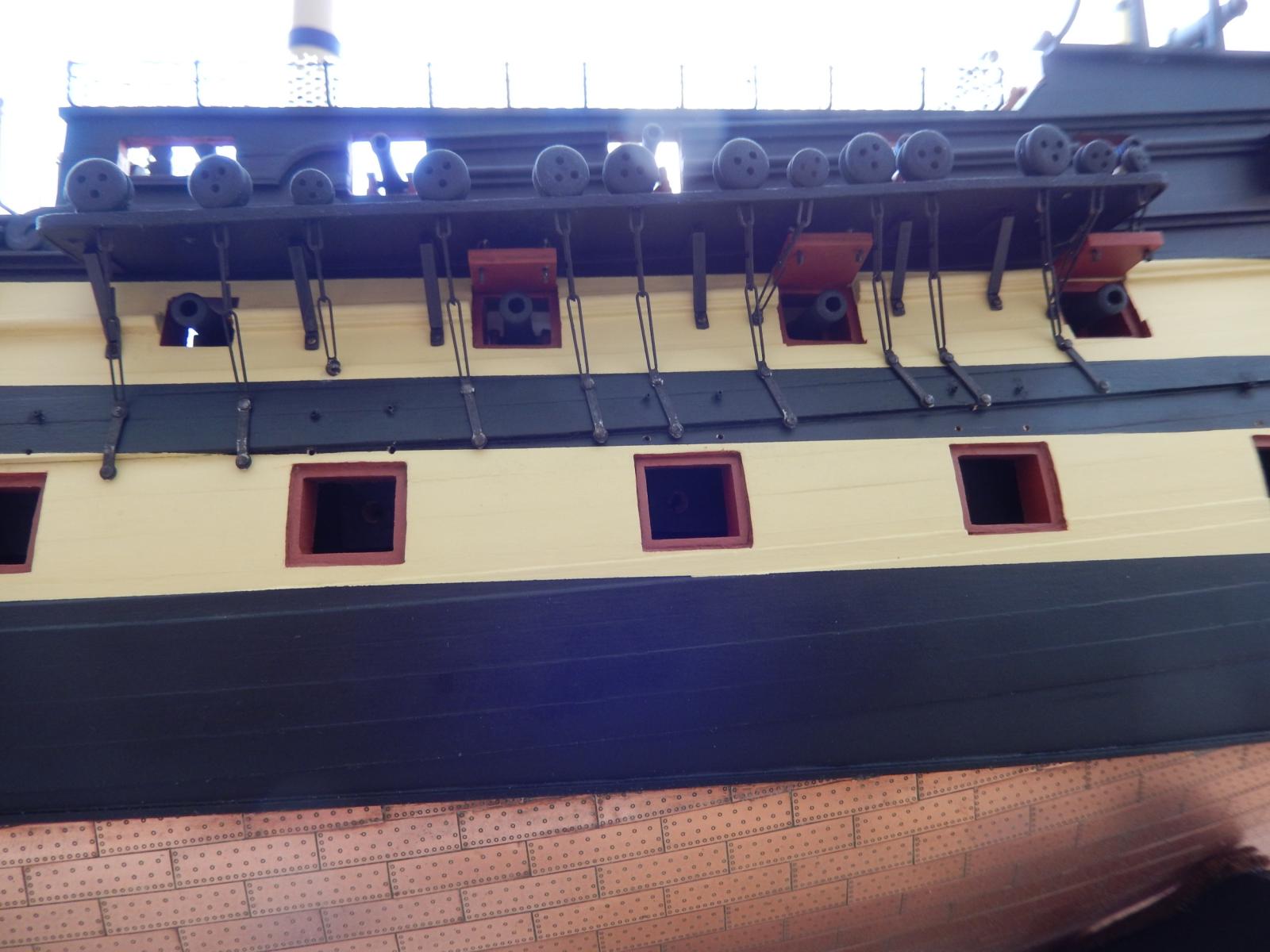
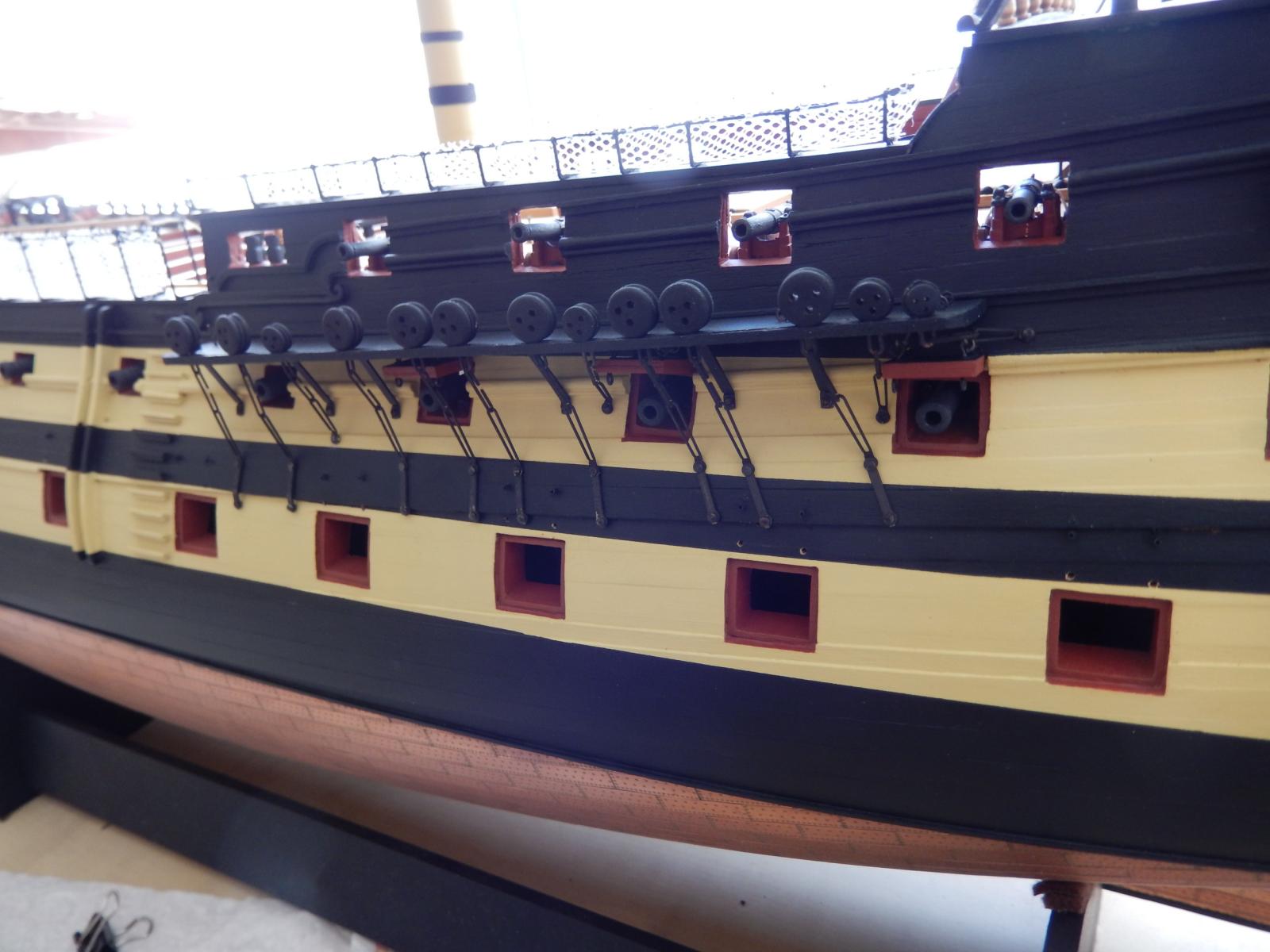
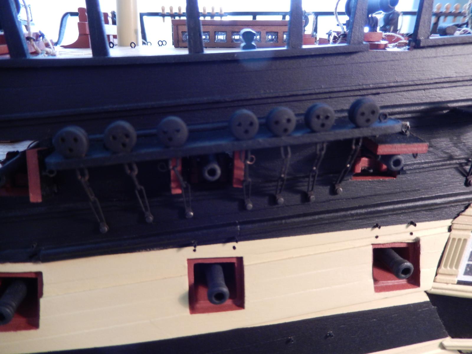
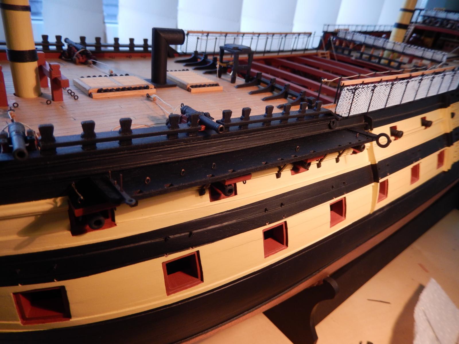
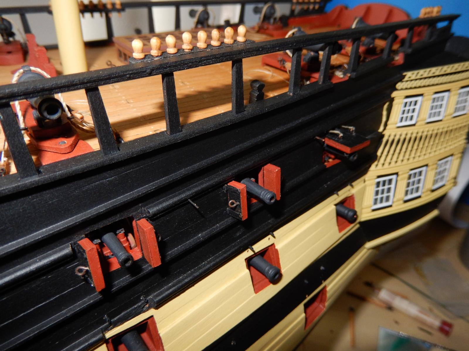
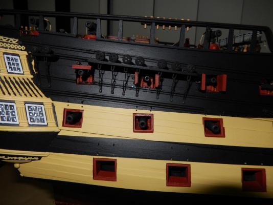
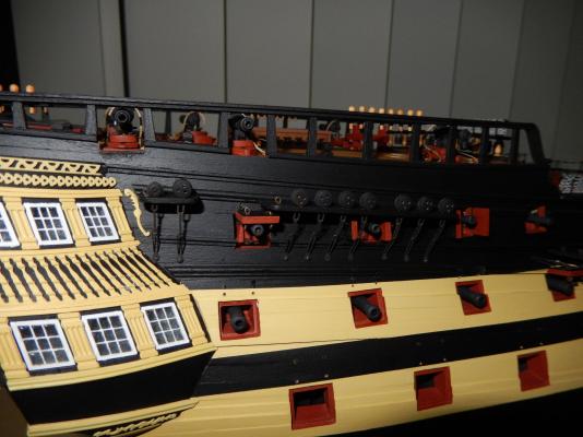
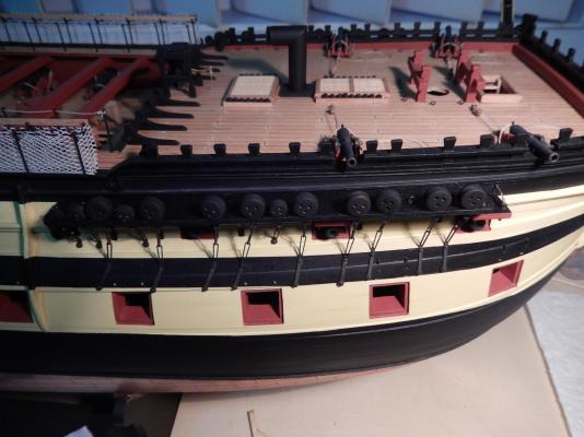
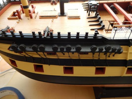
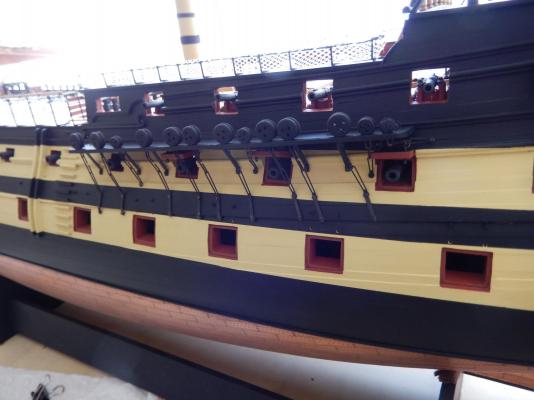
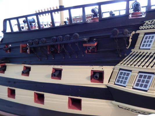
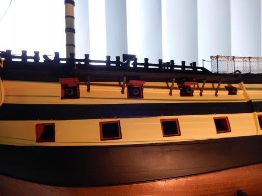
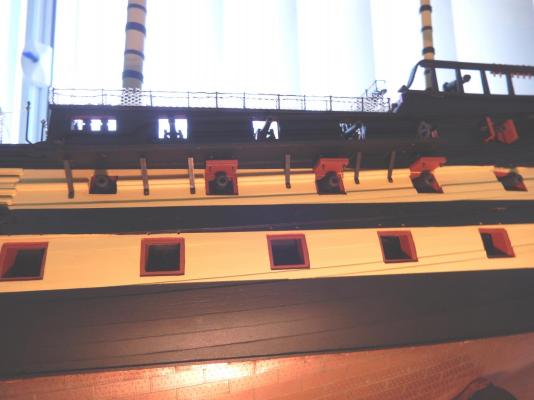
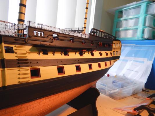
The channels and the brackets are now fixed to the port side of the ship, together with the other hardware. The channel stun sail boom fittings are dry-fitted at this stage. Sticking out as they do is an invitation to catch on something. Fitting the channels was easier than I expected, though I think that things going well is often more a matter of luck than anything else. The brackets on the forward channel did just fit. It remains to be seen if the starboard side will go as well. I will leave the remaining gun port lids off as long as possible; again they are an invitation to disaster. I'm afraid there is a sameness about the photos, but I have sometimes found in looking at other logs, that what I really wanted to see is just out of the picture. Here I have tried to show as many different views as possible, and hope they may be useful. Now for the starboard.


-
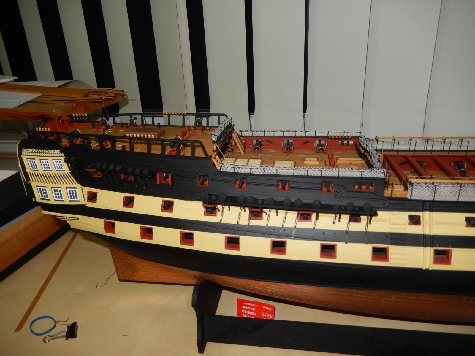
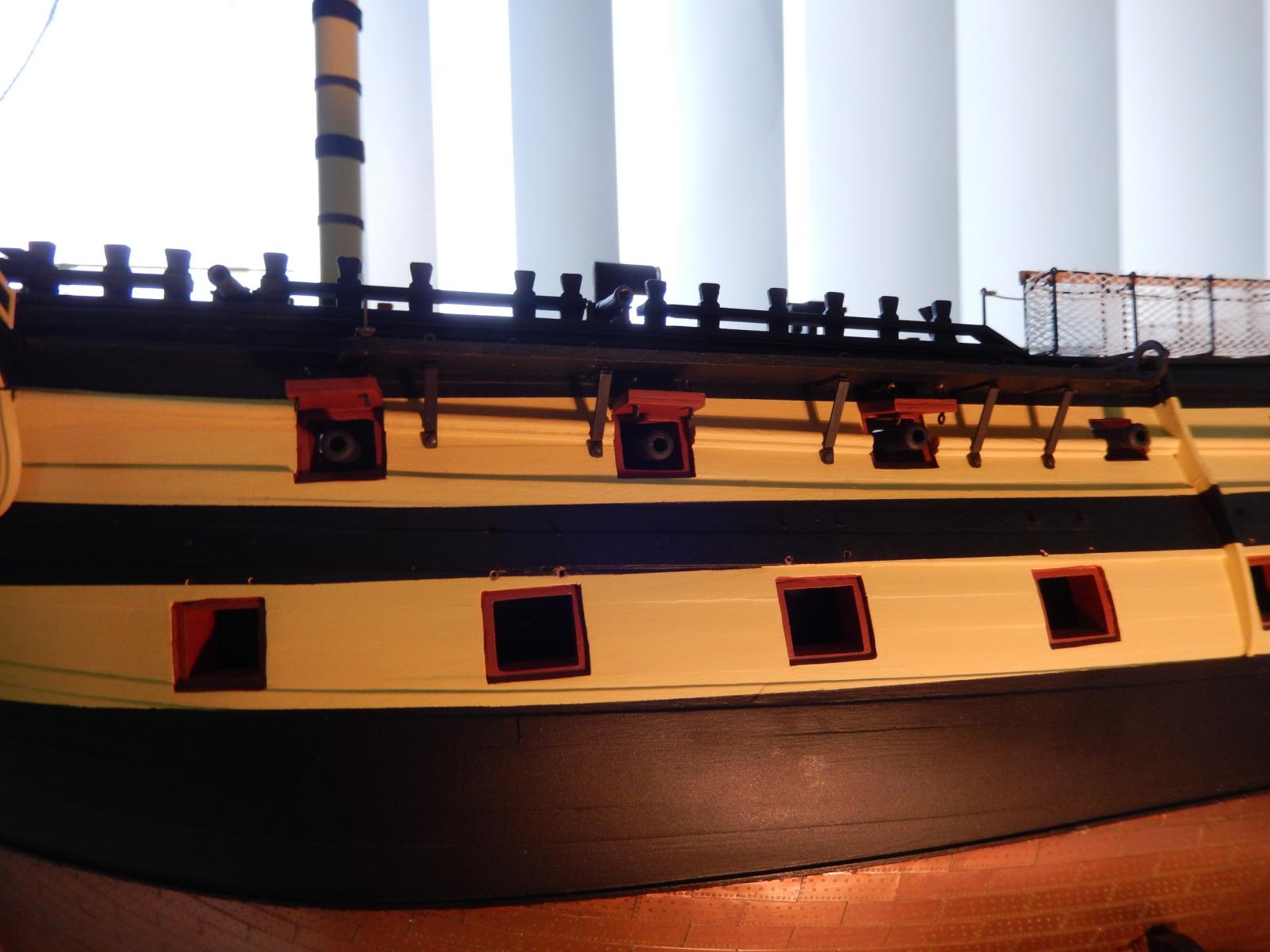
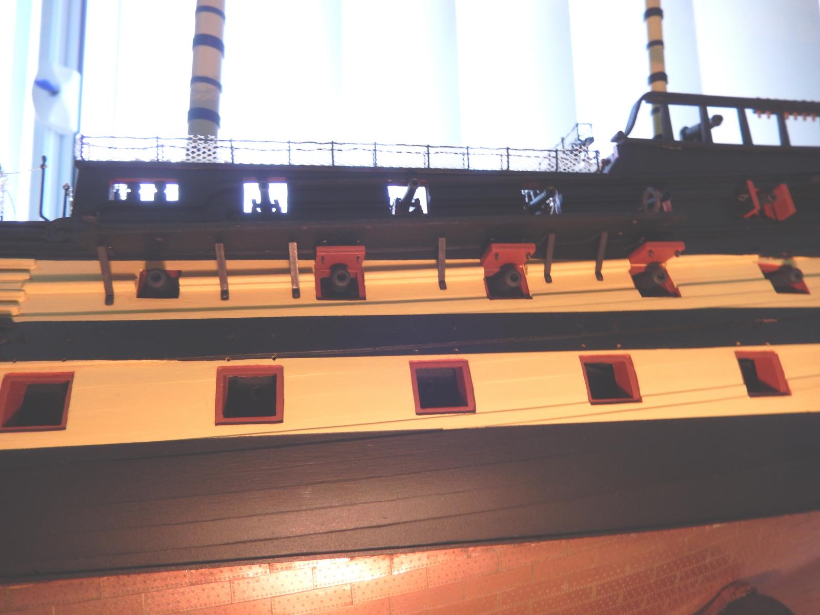
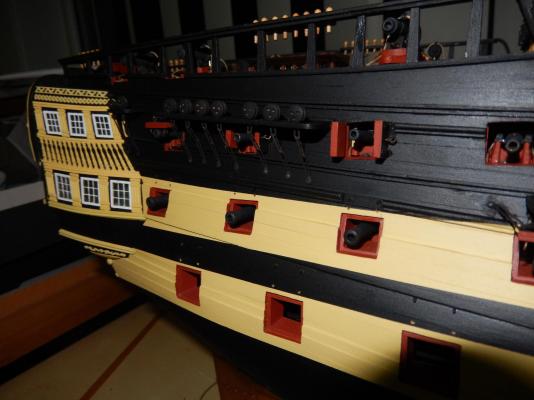
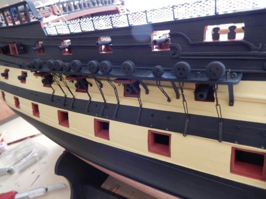
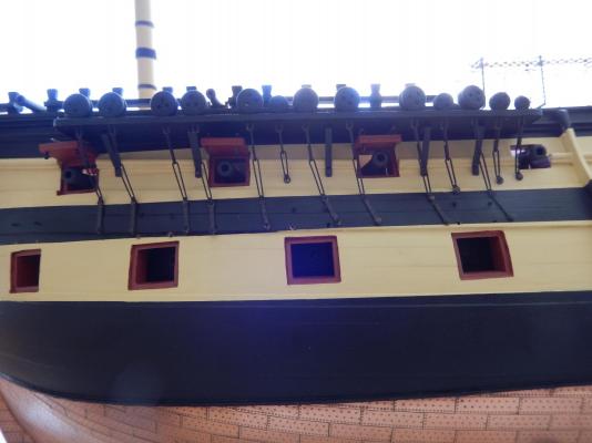
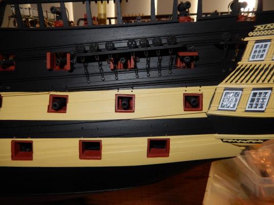
The lanyards are now on the potentially troublesome gun port lids and those lids are now installed. I came across a god way of 'splicing the lanyards to the lids (I think Gil Middleton's log). Take a very fine needle and thread the line through the eyelets. Once through thread the line through itself once, then again through the other side of the line. Then pull the needle and thread tight and the lanyards attached to the eyelet on the lid. The line is very fine indeed. Good short vision helps, so this may not be for everybody. Now that the lids are complete I have installed the channel brackets on the forward channel and dry fitted the channel to the model. The brackets come perilously close to the molding, though I think they will just - only just - fit. If the molding was 1/2mm higher it would make things a lot more comfortable. I do have a cunning fallback plan if, when the channel is properly installed, the brackets are too close the the molding but at this stage I'll assume things will turn out well. Here are the forward gun port with lanyards. With the channel dry-fitted.


-
Arthur: I noticed I also transposed 'so now' in my note to you. How about we come to an arrangement: I'll forget about your channels, and you forget about my arrows. Now where did I put my car keys .........
-
Arthur: The arrows are so now obvious. When I look at the plan again I can't believe how I missed it. It can't be age, surely.
-
I have now finished putting the capping on to the channels. It proved a little easier than I expected. Rather than using the specified 1x2mm strip (I had run out anyway) I substituted 0.5mm strip trimmed down to fit the side sides of the channels (about 1.5mm). I soaked this in household ammonia and was able to bend it around the edges with their almost 90 degree angles fairly easily. If the wood splits on the corners (as it did once or twice) apply a drop of gel CA to the offending part and smooth it down with your thumb nail. It does work: your nail doesn't stick (or at least mine didn't), and you can do it while the wood is still wet. Here is a sample. As well the gunport lids for the three topmost ports have finally been permanently attached. Putting the lanyards on to the lid with the horizontal hinges proved to be difficult. The plans specify the two lanyards to go into a single hole above and in the middle of the two hinges. After a very large number of attempts I gave up, finally putting each lanyard above their respective hinges. There is a bit of cheating entailed in fitting the first of the vertically hinged split doors too. When I dry fitted the channel above the doors it would have touched the top of the doors in a way that its angle to the hull would have been too great (ie. not horizontal to the horizontal plane (if that is not a redundancy)). The doors have therefore each been slightly trimmed on one side to the angle of the channel. With the channel installed it is not noticeable, though I just noticed that I need to touch up the paint work on one of the doors.