


thibaultron
-
Posts
2,669 -
Joined
-
Last visited
Reputation Activity
-

 thibaultron reacted to jdbradford in Modifications to a Dremel Belt/Disk Sander
I am going to try using my new Grizzly belt/disk sander for shapes like that.
Jeff
-
thibaultron reacted to bushman32 in USS Arizona Picture And History Site
Thanks for posting the site.
Ron W.
-
thibaultron reacted to michael101 in table saw
hello
I have a few questions before I buy a table saw
1 . can i cut strips from sheets by Proxxon (fet)
2 . do i need to buy only mini saw for that work or maybe can i buy real table saw like bosch , makita , dewalt ect.
i can't buy the byrnes table saw because I'm from israel and i tried lot of time to send email to hem but never received answer....
anyway in my country i can Choose between proxxon the fet model or to buy "real" table saw
i mean the big one...
By the way the price of the proxxon its expensive i can bay
kind regards
Michael.
-
thibaultron reacted to bushman32 in table saw
The Proxxon is also marketed here in the States by Micro Mark as the Microlux saw. I have had mine for 20 odd years now, and still going strong. With a carbide blade I have cut 3 1/2" thick cherry many times. Saw on one side, flip it over, saw again. My saw has gone through this with no problems. Just feed slowly. With jeweler's blades I have cut strips from thin sheets.The trick is set up and feed rates. What is the thickest wood you plan on sawing?
Ron W.
-
 thibaultron got a reaction from mtaylor in Modifications to a Dremel Belt/Disk Sander
While trying to sand the bowsprit blank for my skipjack model, I ran into a problem. The shield on the disk sander part of my Dremel Belt/Disk Sander projected past the edge of the disk, making it impossible to sand an inside corner, as shown at the left in the photo below.
You can see that I was unable to sand up to the end of the piece.
Also the mount for the table was not stable, it moved out of the angle setting under even moderate pressure.
I decided to cut out part of the shield, so that I could get to those corners, and see why the table was moving.
During disassembly I found that not only were the hinge pins split pins, that can compress under pressure, but also that the hinge hole in the shield was really a slot! The slot allows the table to be slid down and out once the clamp bolts are removed, not a feature I need. I’d rather have a nice tight fit on the hinges.
So I modified the hinges by filling the slot, and drilling the hinge points for the next size 3/16” solid pins. I wish I could have filled the slots with metal, but I did not have any scrap that would not require massive amounts of filling to get small enough. The drilled holes for the pins would cut into the sides of the slots, so I feel that with the hardwood plugs I put in the mount will be strong enough. When assembling the parts, I used medium strength thread locker when iserting the pins.
Any way here are pictures of the modified shield.
-
thibaultron got a reaction from mtaylor in USS Arizona Picture And History Site
Here's an interesting site I found, on the history of the USS Arizona.
https://www.warhistoryonline.com/war-articles/the-uss-arizona-life-and-death-of-an-ill-fated-battleship.html
-
thibaultron reacted to Cap'n Rat Fink in Sea of Galilee boat by Wintergreen - FINISHED
Hello Hakan,
Nice to see you building again. I built 2 of these boats. One for my home, the other went to our church. Have fun I will be watching. This is the 1/24 scale model and the book I used almost extensively plus versus in the bible.
-
 thibaultron got a reaction from trippwj in USS Arizona Picture And History Site
Here's an interesting site I found, on the history of the USS Arizona.
https://www.warhistoryonline.com/war-articles/the-uss-arizona-life-and-death-of-an-ill-fated-battleship.html
-
thibaultron reacted to tasmanian in Modifications to a Dremel Belt/Disk Sander
great idea . i have the same problem with my disk sander
-
 thibaultron got a reaction from tasmanian in Modifications to a Dremel Belt/Disk Sander
While trying to sand the bowsprit blank for my skipjack model, I ran into a problem. The shield on the disk sander part of my Dremel Belt/Disk Sander projected past the edge of the disk, making it impossible to sand an inside corner, as shown at the left in the photo below.
You can see that I was unable to sand up to the end of the piece.
Also the mount for the table was not stable, it moved out of the angle setting under even moderate pressure.
I decided to cut out part of the shield, so that I could get to those corners, and see why the table was moving.
During disassembly I found that not only were the hinge pins split pins, that can compress under pressure, but also that the hinge hole in the shield was really a slot! The slot allows the table to be slid down and out once the clamp bolts are removed, not a feature I need. I’d rather have a nice tight fit on the hinges.
So I modified the hinges by filling the slot, and drilling the hinge points for the next size 3/16” solid pins. I wish I could have filled the slots with metal, but I did not have any scrap that would not require massive amounts of filling to get small enough. The drilled holes for the pins would cut into the sides of the slots, so I feel that with the hardwood plugs I put in the mount will be strong enough. When assembling the parts, I used medium strength thread locker when iserting the pins.
Any way here are pictures of the modified shield.
-
thibaultron reacted to antanasp in Double Boat by antanasp - Master Korabel - Scale 1: 72, Russian fleet double boat 1736-1737
In the next step I checked the hull construction. I attached all parts together and get the hull. Any glue at this step not used. All fit very well, not needed any sanding to connect parts together. The hull geometry seems are good too. I am very satisfied... And the result photos:
-
thibaultron reacted to Walter Biles in America by Walter Biles - scale 1:48 - RADIO - POF schooner from BlueJacket Shipcrafters plans
Thanks Ron,
That gives me quite a bit to work on. It looks like you have done a pretty thorough job of it. Now I can study and cogitate for awhile, and see if I can follow everything okay. I have printed this log page 2 to here, and added the blown up pictures right behind each page with the text for clearer sight. I will see what I can come up with. Thank you so much.
-
 thibaultron got a reaction from Walter Biles in America by Walter Biles - scale 1:48 - RADIO - POF schooner from BlueJacket Shipcrafters plans
Part 3 of 2D to 3D
Deselect the original and select the new frame, at the crossing of the baselines (shown by the solid dot after selecting.)
I have restored the 3D windows, and I’m getting ready to move the frame into position. With the “Move” command (see menus in picture).
After you select “Move” the frame will be shown with black lines to show where it will move to, if you click the mouse. The original frame is shown still in place, until the “Move” operation is completed
I then selected the crossing of the baseline, and station for this frame. I’ve been using the “Point – Intersect – 1” (or F4) to select all these crossing points.
This completes the” Move” operation, The frame has been moved so that the point used to select it (the baseline crossing point), has been placed on the second point selected, the baselines station crossing.
Here is the frame after I zoomed in a bit.
And a bit more.
Here I’ve removed the station line.
The rest of the frames are moved in the same way.
Note that in this earlier drawing, I had already drawn the keel line, and I am using that as the final move point, thus I did not have the baselines in these frame drawings. The way I show in this post is better.
If you look you can see I have a problem, as the frame waterlines are not matching the reference waterline. This is from the original drawing I made from the scanned book page, before I bought the full sized drawing.
After all the frames are in place you can remove the frame baselines. Before you do, look at the other views and make sure that none of the frames is out of position.
-
thibaultron got a reaction from Walter Biles in America by Walter Biles - scale 1:48 - RADIO - POF schooner from BlueJacket Shipcrafters plans
Part 2 of 2D to 3D
This is the front view window expanded. We need to change the frames from the group we made earlier, so that we can move the individual ones. Select a point anywhere on the frames, and going back to the “Tools – Groups menu select “Break Group”.
Now I have selected just the lines for one frame, and made them a group. Note that the solid dot is in the middle of the frame, this means that the group was selected by clicking somewhere inside the group boundaries.
The frame is pointed in the “wrong” direction, I am placing all the frames on the starboard side to build the hull, and this one would end up on the port side. Deselect the frame group, and reselected it at the crossing of the baselines. Now I have to mirror the frame to reverse it.
The above picture shows the menu selections to do this.
As this is the front view I have to mirror it on the Z axis. I generally pick the wrong axis, and have to redo it until I pick the right one. I use the “Make A copy” option, that way I’m not risking the original, if I make a mistake. The black frame is the mirrored copy, that is displayed when you move your cursor off of the menu box. The mirrored frame will move with the cursor, until you click the mouse, then it will be dropped on the drawing where the mouse was.
There is the mirrored frame. If the original was a group the mirrored one will also be a (separate) group.
-
thibaultron got a reaction from Walter Biles in America by Walter Biles - scale 1:48 - RADIO - POF schooner from BlueJacket Shipcrafters plans
Going from the 2D drawing to a 3D drawing.
This will be in at least 2 parts, as I have too many drawings to fitt in one post.
Above is the drawing I’m going to start from. I have developed the frames on the upper right to individual frames, on another layer, as part of this drawing.
Here is the layer with the frames. I have selected them all, and am making them a group, using the menu selection shown. Making them a group makes them basically one thing/entity. The CAD program will act on all of the grouped lines as a single thing, not separate lines.
I’ve now gone to the 3D mode, by selecting the 3D button in the menu system. Note that the lines are still in the proper relationship, as shown in the upper left window. The lines look skewed in the main window, because we are looking down and a little to the side. Note the 3D viewing angle settings in the lower right bottom main menu. If all the settings are at zero, the drawing is displayed as if it was a 2D drawing. You have to crank in some values so that you can see the 3D view.
The baselines, fore and aft parallels, and the station lines have been drawn, along the XY plain (Z=0). The red lines are the baseline, and parallels. The green lines are the waterline, and station lines.
These are actually the ones from the 2D drawing, I’ve just turned on those layers. All the 2D lines you drew will be displayed on the XY plain in 3D. Placing different sections of the drawing on different layers allows you to hide those layers when working on another section. For example the station lines and baselines are on different layers. I hid them when I was working on the spars, to cut down on the clutter on the screen.
Once again you can see that they are not skewed in the Top, Side, and Front views.
In this picture I’ve turned on the layer with the completed frames. The curve lines are the deck, with the camber.
Here the frames are all selected, and made a group. I have also made the baseline, etc. a separate group.
I cleared the selection, and reselected the frame group, at one of the intersections of the baselines. The selected point is the solid dot. The square boxes are the individual line end points. There is an option in the “Options” menu “Point Select Mode” that turns this on and off, if you don’t want it.
I forgot to save the screen when I was rotating the frames, so the above drawing is the main one. I selected some lines, and am getting ready to rotated them. This picture is to show how to get to the rotate command.
When you select rotate this new menu window pops up. We want to rotate the frames to be perpendicular to the baseline, so select rotate around Y axis, enter 90 deg. For the rotation angle, and deselect the “Drag Mode” option.
Now when you move your cursor away from the box, it will be displayed as a curved line and arrow symbol. Move the symbol to the main windows, and click. I could not get the screen capture to show this symbol.
The frames have been rotated, and the frame group is being broken, so that we can work on the individual frames.
-
thibaultron got a reaction from Walter Biles in America by Walter Biles - scale 1:48 - RADIO - POF schooner from BlueJacket Shipcrafters plans
In DesignCAD You can try Control-Shift-R. This will refresh all the screens, not just the one you are on. Or Control -Shift-W, this will resize the drawing in all the windows to fit the entire drawing in them.
If you lost one of the 3D window panes, the menu option "Windows", "DesignCAD Tile Settings", "Restore DesignCAD Tile" will restore the screen to the 4 windows of the standard 3D setup.
-
thibaultron got a reaction from mtaylor in America by Walter Biles - scale 1:48 - RADIO - POF schooner from BlueJacket Shipcrafters plans
Part 3 of 2D to 3D
Deselect the original and select the new frame, at the crossing of the baselines (shown by the solid dot after selecting.)
I have restored the 3D windows, and I’m getting ready to move the frame into position. With the “Move” command (see menus in picture).
After you select “Move” the frame will be shown with black lines to show where it will move to, if you click the mouse. The original frame is shown still in place, until the “Move” operation is completed
I then selected the crossing of the baseline, and station for this frame. I’ve been using the “Point – Intersect – 1” (or F4) to select all these crossing points.
This completes the” Move” operation, The frame has been moved so that the point used to select it (the baseline crossing point), has been placed on the second point selected, the baselines station crossing.
Here is the frame after I zoomed in a bit.
And a bit more.
Here I’ve removed the station line.
The rest of the frames are moved in the same way.
Note that in this earlier drawing, I had already drawn the keel line, and I am using that as the final move point, thus I did not have the baselines in these frame drawings. The way I show in this post is better.
If you look you can see I have a problem, as the frame waterlines are not matching the reference waterline. This is from the original drawing I made from the scanned book page, before I bought the full sized drawing.
After all the frames are in place you can remove the frame baselines. Before you do, look at the other views and make sure that none of the frames is out of position.
-
thibaultron got a reaction from mtaylor in America by Walter Biles - scale 1:48 - RADIO - POF schooner from BlueJacket Shipcrafters plans
Part 2 of 2D to 3D
This is the front view window expanded. We need to change the frames from the group we made earlier, so that we can move the individual ones. Select a point anywhere on the frames, and going back to the “Tools – Groups menu select “Break Group”.
Now I have selected just the lines for one frame, and made them a group. Note that the solid dot is in the middle of the frame, this means that the group was selected by clicking somewhere inside the group boundaries.
The frame is pointed in the “wrong” direction, I am placing all the frames on the starboard side to build the hull, and this one would end up on the port side. Deselect the frame group, and reselected it at the crossing of the baselines. Now I have to mirror the frame to reverse it.
The above picture shows the menu selections to do this.
As this is the front view I have to mirror it on the Z axis. I generally pick the wrong axis, and have to redo it until I pick the right one. I use the “Make A copy” option, that way I’m not risking the original, if I make a mistake. The black frame is the mirrored copy, that is displayed when you move your cursor off of the menu box. The mirrored frame will move with the cursor, until you click the mouse, then it will be dropped on the drawing where the mouse was.
There is the mirrored frame. If the original was a group the mirrored one will also be a (separate) group.
-
thibaultron got a reaction from mtaylor in America by Walter Biles - scale 1:48 - RADIO - POF schooner from BlueJacket Shipcrafters plans
Going from the 2D drawing to a 3D drawing.
This will be in at least 2 parts, as I have too many drawings to fitt in one post.
Above is the drawing I’m going to start from. I have developed the frames on the upper right to individual frames, on another layer, as part of this drawing.
Here is the layer with the frames. I have selected them all, and am making them a group, using the menu selection shown. Making them a group makes them basically one thing/entity. The CAD program will act on all of the grouped lines as a single thing, not separate lines.
I’ve now gone to the 3D mode, by selecting the 3D button in the menu system. Note that the lines are still in the proper relationship, as shown in the upper left window. The lines look skewed in the main window, because we are looking down and a little to the side. Note the 3D viewing angle settings in the lower right bottom main menu. If all the settings are at zero, the drawing is displayed as if it was a 2D drawing. You have to crank in some values so that you can see the 3D view.
The baselines, fore and aft parallels, and the station lines have been drawn, along the XY plain (Z=0). The red lines are the baseline, and parallels. The green lines are the waterline, and station lines.
These are actually the ones from the 2D drawing, I’ve just turned on those layers. All the 2D lines you drew will be displayed on the XY plain in 3D. Placing different sections of the drawing on different layers allows you to hide those layers when working on another section. For example the station lines and baselines are on different layers. I hid them when I was working on the spars, to cut down on the clutter on the screen.
Once again you can see that they are not skewed in the Top, Side, and Front views.
In this picture I’ve turned on the layer with the completed frames. The curve lines are the deck, with the camber.
Here the frames are all selected, and made a group. I have also made the baseline, etc. a separate group.
I cleared the selection, and reselected the frame group, at one of the intersections of the baselines. The selected point is the solid dot. The square boxes are the individual line end points. There is an option in the “Options” menu “Point Select Mode” that turns this on and off, if you don’t want it.
I forgot to save the screen when I was rotating the frames, so the above drawing is the main one. I selected some lines, and am getting ready to rotated them. This picture is to show how to get to the rotate command.
When you select rotate this new menu window pops up. We want to rotate the frames to be perpendicular to the baseline, so select rotate around Y axis, enter 90 deg. For the rotation angle, and deselect the “Drag Mode” option.
Now when you move your cursor away from the box, it will be displayed as a curved line and arrow symbol. Move the symbol to the main windows, and click. I could not get the screen capture to show this symbol.
The frames have been rotated, and the frame group is being broken, so that we can work on the individual frames.
-
thibaultron reacted to torpedochief in Decking for small models, well any models
Shipmates!!!
Discovered this while I was looking for a better way to make draft marks for my submarines. DECALPRO offers a nice easy system to make your own dry transfer decals.
Using this system I came up with ways to make decking. With this technique material thickness will not be an issue, and it can be used on any surface.
As always there are a few issues with a new technique. You will require a laminating machine recommended by the manufacturer. I found one on Ebay. You also need a laser printer, and a heat gun.
You can do like I did and create your decking in the PAINT program on windows. (NOTE: This deck is way out of scale and proportion so I could show you the technique.) You can also hand draw the deck and then scan it in your computer, or you can find deck patterns on the Net.
The decal instructions will show you exactly what to do to set up the special decal paper and transfer Mylar film. The laser printer uses toner which is plastic. When printed on the special paper the image is bound to the paper by a water soluble chemical. A Mylar carrier sheet is laminated to the special paper. This causes the image to bond with the Mylar carrier sheet with static. The deal is then given a water bath where the chemical in the paper releases the image to the Mylar film. The image is dried with a paper towel then sprayed with an alcohol based adhesive.
For demonstration I used a piece of Mahogany. The image is laid down and rubbed with a paper towel. Then the backing is peeled away.
For the colored deck. I demonstrate on white card stock. If you choose to place your deck on say grey polystyrene then you will have to reverse your image in the computer,apply the white foil film to the back and then use the carrier Mylar.
You can use this system to make name plates, sails, just about anything.
Enjoy!!
-
thibaultron reacted to antanasp in Double Boat by antanasp - Master Korabel - Scale 1: 72, Russian fleet double boat 1736-1737
Thank's thibaultron .
Instructions are available: photomanual - Russian and Lithuanian; instrukcions - Russian come with kit and Lithuanian, English or France are available for downloading. Later will be added Germany and Poland. Maybe more...
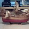
Brief historical note. Double boat –in archive documents was named as double boat. It’s a small sail and raw war ship designed for operations in the rivers, coastal lakes and near the coast line. Double boats appeared in 30th of the XVIII century and were predecessors of gunboats, besides their principal “battling” function they also served as advice boats and ran a mission of landing forces and transportation. Particularly outstanding event was connected with large-scale construction of such class of ships for developing the Dnepr Fleet at time of the war between Russia and Turkey in 1735—1739. The reports from Collegium Admiralties to the Senate of Sept.06, 1736 inform: “...named as double boats are made like standard boats for war ships but as compared to the last have double size”. Drawing for the new ship was made by Oberin intendant R. Broun. Based on those drawings a sample half-model was constructed which is now stored in the Central Naval Museum. Double boats under this project were lateen rigged on two masts. Artillery armament included six 2 pound falconets mounted onto wrought cradles. Double boats were aimed for support of the Russian military forces operating along the Dnepr and its coastal lake coast lines. In case of necessity theycould transport up to fifty armed people and two regimental cannons. On June 19, 1736 the Senate ordered to build 500 double boats in Bryansk dockyards. As far as the boats were constructed the same were driven down the Dnepr to the military operations area and were actively involved in operations: gunned enemy lines, transported forces. During navigation in 1737-1739 double boats actively participated in military operations conducted by Field Marshall Minich. On July 02, 1737 Russian forces took by storm Ochakov fortress which should become the Dnepr Fleet harbor. On Sept. 3, 1737 Naum Akimovich Senyavin was appointed as the Fleet Commander. Toward June 1737 in Bryansk there were built 202 double boats. As early as on October 30, 1737 the Dnepr Fleet ships participated in holding off an attack of 40 thousands’ Turkish army on Ochakov supported by twelve galleys. Later double boats constantly fired on Turkish army lines near Ochakov, one of them under the command of warrant officer Chikhachiov attacked by fire during the whole day so intensively that its falconet cradles broke to pieces. As far as summer of year 1738 near Ochakov and Kinburn there were already 254 double boats. Plague epidemic broken out in May 1738 overset plans of belligerent parties and on the 2nd of September the Russian army command decided to evacuate military reservations of Ochakov and Kinburn fortresses and to destroy fortification works of the same. In the middle of September the Dnepr fleet of 347 ships with Russian army onboard arrived to Khortitsa island and the Samara river estuary. Here the ships were stationed until conclusion of peace between Turkey and Russia on September 18, 1739. In Russia there were several occasions when similar kind of boats was constructed. Three double boats were built in 1733—1737 for the Second Kamchatka Expedition led by Vitus Bering. In Tobolsk the boat named “Tobol” was built in 1733 for the team of D. Ovtsyn lieutenant which aimed to reach the Ob river estuary and arrive to the Yenisei river estuary. In Yakutsk the boat named «Yakutsk» was constructed (it was laid down in spring of 1734 and set afloat in spring of 1735) for the team of V. Pronchischev lieutenant for study of the Lena river and preparing description of Siberia coastline up to the Yenisei estuary. In Okhotsk the boat named «Nadezhda» (set afloat in 1737) was build for the team of V. Walton lieutenant dealing with search of pathways to Japan. The first two boats were build based on the drawings sent from Saint-Petersburg, had 24 oars, the hull length of 21.48 m and the width of 5.48 m. The third one was three-masts double boat with gaff rig, had the length of 24.5 m, the width of about 6 m, the depth of hold of 1.8 m and was built by foremen Rogachov and Kuzmin A. -
thibaultron reacted to antanasp in Double Boat by antanasp - Master Korabel - Scale 1: 72, Russian fleet double boat 1736-1737
Hello. This is my first post on MSW. Thank's for You comments, understunding and help.
The DB kit is maded in Russia by company Master Korabel(Milanija). They have a line of 7 kits and in this year will appear 2 new kits. This is the 3-rd kit that I build from this company. I dont now if show 2 other builds? If it is interesting, I can open new build logs. Now some words about the kit and content. Kit features: All hull planking and details are laser cut, the marked bevels on frame, a special hull design that compensates the material deformation, detailed photo instruction and drawings, patterns and cloth for the sail sewing and many others. The Master Korabel make a big research work for this model. The model will be 300 mm lenght, 76 mm width and 260 mm height. And now the kit content:
Oars
Other elements
-
thibaultron got a reaction from mtaylor in America by Walter Biles - scale 1:48 - RADIO - POF schooner from BlueJacket Shipcrafters plans
In DesignCAD You can try Control-Shift-R. This will refresh all the screens, not just the one you are on. Or Control -Shift-W, this will resize the drawing in all the windows to fit the entire drawing in them.
If you lost one of the 3D window panes, the menu option "Windows", "DesignCAD Tile Settings", "Restore DesignCAD Tile" will restore the screen to the 4 windows of the standard 3D setup.
-
 thibaultron got a reaction from vossiewulf in Gluing Techniques and Associated Information
In an earlier post someone mentioned that their CA was not bonding parts. I had this problem with a bottle of CA. It would go on the surface, but when you pressed the parts together, nothing, even though the glue was "wet" when the parts were pressed together, and "dry when I released the parts.. I bought another bottle and it worked fine. There was something wrong with that first bottle. In 25 years of using CA, this was the first time it had failed to bond.
I have never had the CA let go of a glued model, but I have found it to become brittle after time, and fail after a hit on the model sometimes. This was on RC ships that take a beating, and have less ribs than would be typical of a regular RC hull.
-
thibaultron reacted to bear in Gluing Techniques and Associated Information
Ahoy Mates
When I stated using boxwood and swiss pear for planking I did some tests as to how good Titebond held it. Since it's a hardwood and the grain structure is very tight and dense,the gklue did not hold it as well as basswood that I was used to.
To give the glue more surface and texture to grab onto I have started using a xacto razor saw blade to scratch the surface that will be glued. I use the side of the teeth on the blade to groove the planks surface. It looks like what you see when you use a toothed trowel for laying down glue for tile work.
I also use this method to make wood grain on basswood before staining. The grooves add to the total surface area and roughness that the glue has to bind to for added holding power.
It also prevents you from pushing all of the glue from under what you are gluing together by pressing them together. With the grooves there is always some glue between the parts to hold. And it cuts down on the amount of glue coming out from under the plank.
It also works for CA.
Try it out and let me know what you think of this way of prep for gluing planks and other parts down. And try it to simulate wood grain on basswood and other types of wood and materials. It works on plastic also.
Keith