
MORE HANDBOOKS ARE ON THEIR WAY! We will let you know when they get here.
×


Mark P
-
Posts
1,763 -
Joined
-
Last visited
Content Type
Profiles
Forums
Gallery
Events
Everything posted by Mark P
-
 Good Morning All; Another suggestion for Ferrus Manus re a good book to purchase for information about galleons is Peter Kirsch's book 'Galleon', which is based around contemporary sources, and contains plans for a complete galleon. I don't remember my copy being particularly pricey when I bought it. All the best, Mark P
 -
backing up a log
Mark P replied to Knocklouder's topic in Using the MSW forum - **NO MODELING CONTENT IN THIS SUB-FORUM**
Evening all; For anyone who is still interested in this topic, I have found a reliable method to copy a log or post, with the creator's permission. This is for Windows; I have no idea how this would play out in Mac. Right click on the current page, and this brings up a context menu. Click on 'Save as', and create a folder for the saved image where you want it to be. Name it, and save it. Job done! This will save the entire page you are on; not just the visible part, but all the rest also. If a build log has 5 pages, you will need to do this 5 times, saving each page separately. This is much faster than working on only what is visible on the screen. The saved images are identical to the screen, nothing is lost. All the best, Mark P -
2nd rate London 1656 – the art of the shipwright
Mark P replied to Waldemar's topic in Nautical/Naval History
Good Evening Martes; You are quite correct in your recall; the wreck is located close to a busy shipping lane, and the prop-wash from passing ships, and tidal scour of the exposed remains, are causing rapid deterioration. A further unhelpful factor is the refusal of Historic England to allow any items to be removed from the wreck site. This means that artefacts and ship's timbers can be observed when they are exposed, but cannot be removed to preserve them. Important pieces of the ship's structure and artefacts have been noted, which have now disappeared without any chance to make an official record or attempt to preserve them. Which is very frustrating for all those who want to know more about this time capsule's contents. It is possible that the circumstances have now changed, and recovery of at-risk artefacts etc is now allowed; my information is not up-to-date; but I am not overly hopeful of anything involving a complicated bureaucracy's minions. Especially as many of them are now, post Covid, probably 'working' from home. There is a charity devoted to preserving/raising the remains, 'Save the London', managed by the Nautical Archaeology Society. All the best, Mark P -
Good Evening Rob; I wish you all the best with your project. The model of Bristol in the Ontario Art Gallery has always been one of my favourites. It is also one of the very rare examples where the name of the builder, and the date of the model are known. A note was found inside her, informing posterity that she had been built by George Stockwell, dated 7th May 1774. A further line informs us that he was a shipwright at Sheerness Yard, which is where the Bristol was built, so he presumably knew her very well. The draught is a beautiful example of art; its rendition of the internal details of the ship is one of the highest quality examples of which I am aware, and it is my intention to purchase a digital copy of the draught one fine day when funds are plentiful. Interestingly, the frieze on the model does not match that shown on the draught. All the best, Mark P
-
In early records, late Elizabethan, or early Stuart, the jolly boat is generally referred to as a 'jolly-watt'. Don't ask me why! All the best, Mark P
- 24 replies
-
- 6
-

-

-
- Small boats
- cutter
- (and 2 more)
-
Good Morning Allan; There are other examples from this period of made yards for 74 gun ships and larger. Some are made by splicing on a piece at one end only; others by joining in the middle in the same manner as deck beams were scarphed, with tabled joints; and others as per your example above, with both ends spliced. The dimensions for a main yard at this period does seem to have been 22 5/8" diameter, with a length of 95'. As has been discussed for masts previously, this is quite probably related to the loss of the American colonies, leading to a shortage in the supply of longer trees previously used for yards. However, made masts go back long prior to this period of time, so they were certainly nothing new. I have no information about yards, though, and when they were first made in more than one piece for large square sails. All the best, Mark P
-
Good Morning Thor; I assume that you are building the Royal Caroline of 1749. There are multiple paintings of her in existence, and they all seem to show the masts and yards the same. Masts are natural wood colour, except for the sections between the trestle trees and the cap, which are black. The bowsprit is black, but the jib-boom is natural. All the yards are black. Ensign staffs fitted above the top-gallants (if fitted) are also black for their entire length. All the best, Mark P
-
Prize Papers lecture from the National Archives, U.K.
Mark P replied to druxey's topic in Nautical/Naval History
same here -
Good Evening All; Well, I must say full marks to the people at SeaWatch. I ordered 3 books on Monday 5th December, and they arrived at my home in England today, the 9th December. That's damned good service, and deserves a mention in dispatches. Thank you one and all involved; whoever does the shipping is obviously well-organised, and worth the cost. I shared Druxey's pessimism, I have to admit, and did not expect to receive anything for at least another week. All the best, Mark P
-
Good News for all nautical book addicts: I have just ordered the three volumes of Ed Tosti's Young America work (more for techniques, tips and jigs, as I am unlikely to ever build the model) and not only is there a discount for purchasing the three together, the postage for all three to England was only $35 total. Shipping costs have indeed been reduced dramatically. All the best, Mark P
-
Good Evening Bruce; One small point to note is that there does not appear to have been a standard stave width, with the cooper making a stave as wide as each piece of wood would allow. I have seen old barrels, and frequently the staves vary in width quite noticeably. All the best, Mark
-
Royal navy - stern colours?
Mark P replied to Vane's topic in Painting, finishing and weathering products and techniques
Good Evening Allan; I would not be guided too much by the colours displayed in the model of Granado. Whilst she is a beautiful model, I am pretty sure that it was actually constructed by Bob Lightley? in the 20th century, and purchased by the NMM at around the same time as they also bought the excellent model of the Egmont, built by (Oh God! I can't remember his name! Mind is going!) Which is not to say that the colours shown are not in accordance with contemporary sources, of course. All the best, Mark P -
Mathew Baker's early concept of ship hull design, ca. 1570
Mark P replied to Waldemar's topic in Nautical/Naval History
Definitely 90 in the original, not 93. Phineas Pett, in his autobiography, spells Baker's first name with one 't', as Wayne mentions above. All the best, Mark P -
Mathew Baker's early concept of ship hull design, ca. 1570
Mark P replied to Waldemar's topic in Nautical/Naval History
Good Morning Waldemar; You may find the following description of the construction of a mid-ship mould, by Matthew Baker, to be of use. This is from a contemporary document in the British Library, which I transcribed several years ago. All the best, Mark P Matthew Baker How to draw Mid section MSW.pdf -
Good Morning All; I am not sure if this was mentioned before in another thread on this painting, but there is some indication that Lely (if indeed it was him who painted the ship) did not work from life, but from draughts or sketches of the ship: this is that the perspective of the quarter galleries is completely wrong. He depicts them as parallel to the waterline, whereas in life the forward ends are considerably lower than the stern ends. The quarter galleries follow the sheer of the ship, which those depicted quite obviously do not, being shown parallel with the deck line (look at the line of slightly open gunports on the lower deck) To my mind, this throws into doubt that anyone of Lely's stature, who quite clearly understood perspective, would have depicted the ship thus if painting it from life. Even if it was not Lely, the artist is clearly highly talented, and the same should apply. All the best, Mark P
-
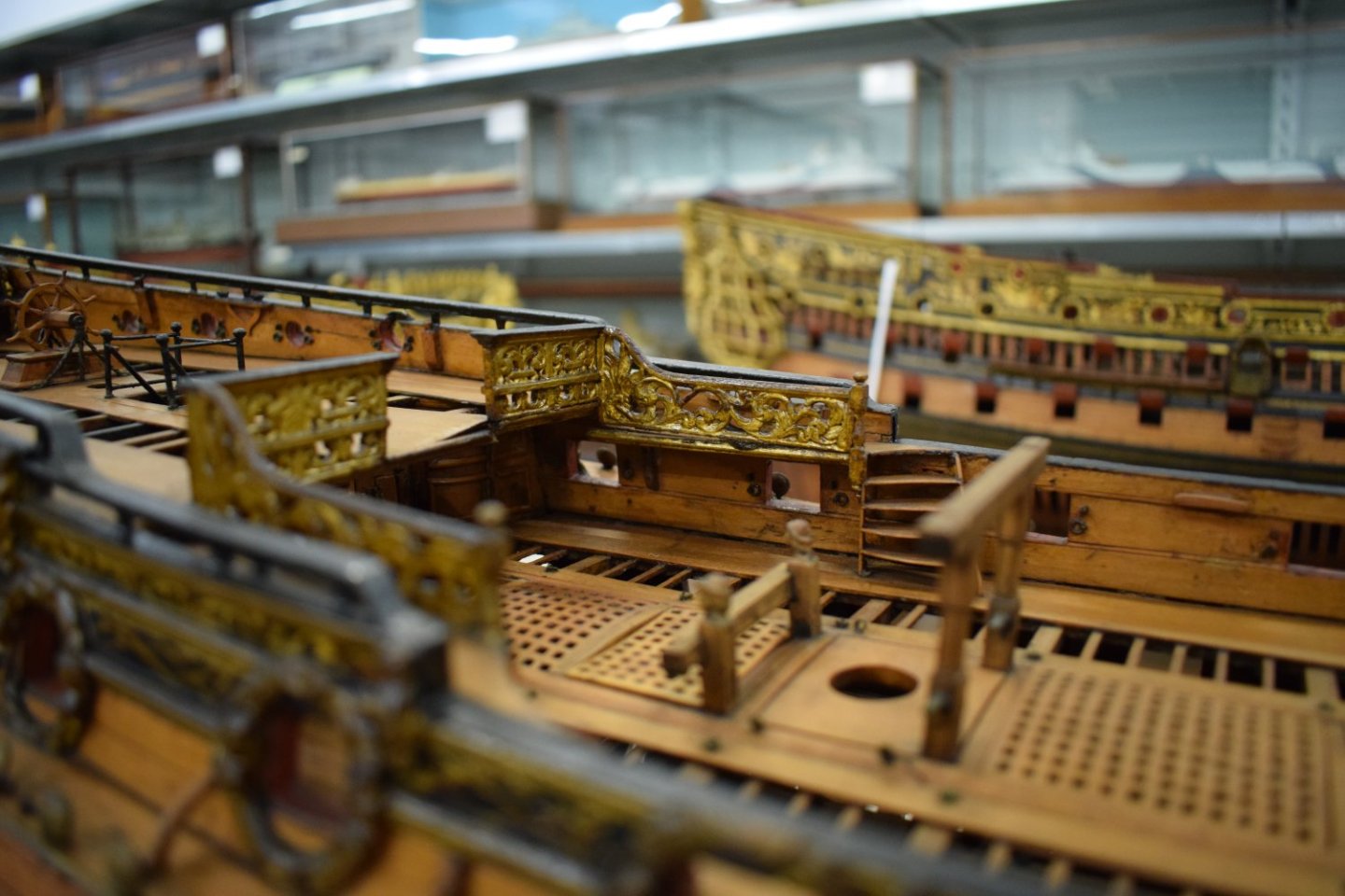
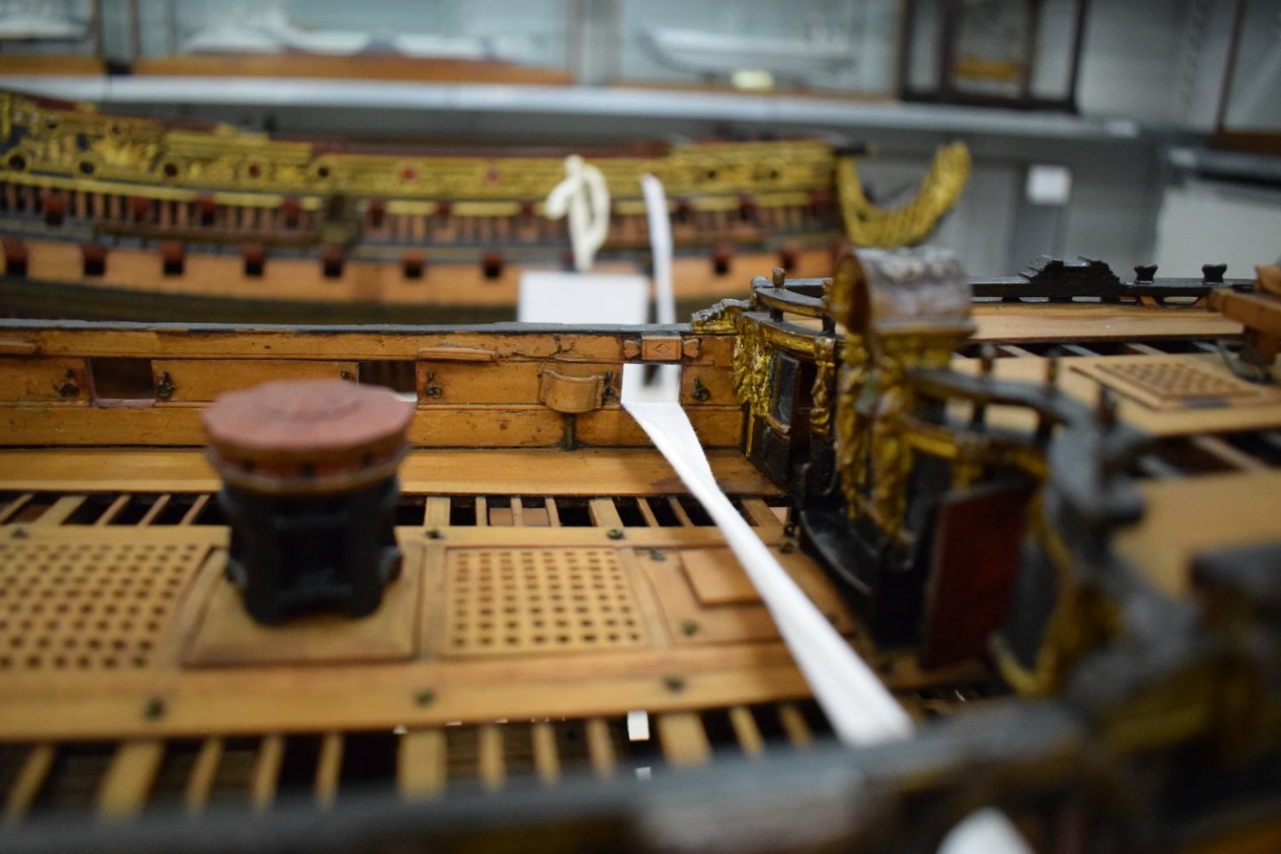
Good Evening Ollie; To judge from the few mentions of such things in early written works, the same belaying points were used from early in the 17th century as are shown on models of a later period. Whilst it is not possible to be certain, it is likely that these also extended backwards to the 16th century. See below photos of belaying points on a model in the NMM's collection, all of which are fixed to the bulwarks. These comprise two forms of cleat, a staghorn and kevel. Cleats and kevels often had sheaves within them. When no specific belaying point was provided, the rope's end was made fast around the fife rail. There is a rigging treatise written around 1625, a transcript of which was published by the Society for Nautical Research. This describes the standing and running rigging of a ship in some detail, and includes details of where the majority of the ropes were belayed: 'belayed to the Gunwale'; 'fastened to the aftermost tymber'; 'belayed to the gunwale under the shrouds'; 'belayed to bit-pins on the fore castell'; 'belayed to 2 cleates set to ether side of the mayne mast'...etc. This is very helpful. I am not sure what you believe to be the date for the start of using belaying pins, but it is most likely that these were in use in the 16th century, as they certainly existed in the early 17th. Sir Henry Manwayring, in his nautical dictionary written around 1623, describes pin racks on the gammoning and on the forecastle head. All the best, Mark P
-
Greetings to anyone interested in this topic: I have recently photographed a document among the State Papers surviving from Charles I's reign, dated 1630. This is a specification for the repair of the Vanguard in dry dock. One item of great interest is this: 'To Birth upp the Sterne on both sides alike, with Buttock planckes wrought out of Rounde Tymber (which I take to mean that the sharply curved planks forming the round tuck were to be sawn out of timber with a suitable curved grain) to bringe on a Transome uppon the Heades of the Buttocke plancke without Boarde to finish the same' (presumably the later tuck moulding, not the wing transom) As the specification was drawn up by Phineas Pett and William Burrell, the two foremost Master Shipwrights in the kingdom, this would make it very likely that this was considered, by this date at the latest, to be normal. If Phineas Pett was involved in specifying a round tuck stern for a rebuild/repair in 1630 it can reasonably be considered unlikely that he would design the later Sovereign of the Seas with a square tuck. All the best, Mark P
-
Mathew Baker's early concept of ship hull design, ca. 1570
Mark P replied to Waldemar's topic in Nautical/Naval History
Good Evening Waldemar; Thank you for the new post. Interesting to follow! To return to the subject of the dead-rise, mentioned earlier in this thread: the deadrise is specified in some early contracts as 4". More interestingly, though, the Salisbury MS of around 1620 describes the deadrise as being necessary to avoid the floors being weakened by cutting the limber holes in their underside; the limber holes instead being cut out of the chocks which were set each side of the keel to form the deadrise. Perfectly sensible when you think about it. Presumably someone soon realised that the bonus was that ships built with a deadrise were more weatherly. All the best, Mark P -
Mathew Baker's early concept of ship hull design, ca. 1570
Mark P replied to Waldemar's topic in Nautical/Naval History
Good Evening Waldemar; Nice to see someone taking a fresh interest in this fascinating work. The original is in the Pepys Library, at Magdalen College, Cambridge. It was written firstly by Baker, and then later, after his death, further pages were added by a second hand, believed to be Wells, the storekeeper at Deptford, although he was much more than this in fact. The second part uses logarithms, which only appeared around 1618, some years after Baker's death in 1613. I have been lucky enough to be able to study this work in the original, although not for as long as I would have liked. It is a fascinating, beautifully illustrated book, which is actually much larger than one might expect, with over a hundred pages. There was an attempt started many years ago to produce a proper commentary on it, something which should have been done long ago. The Pepys Library allowed photographs of the work to be taken to aid in this project (normally almost impossible to do) which was to be a combined effort by two well known specialists. Unfortunately, this has never been completed, with work stalled long ago, and is unlikely to ever be re-started. All the best, Mark P -
Good Evening Michael; My previous answer referred only to the eye-bolts; the plates serve a different function. Without denying their support function, and without being certain of what I am about to say, it is likely that these solid plates were made with an eye in their upper end, to which the lower block of the tackle which ended the shifting backstays could be hooked. These backstays were rigged as additional support for the upper masts when under sail, and would be shifted as the yards were braced further away from the central position. They would only be hauled taut/rigged on the windward side of the mast at any one time. All the best, Mark P
-
Good Morning Michael; These are for use in emergencies, when the chain plates or channels have been carried away by battle or storm damage, and were to enable the attachment of jury rigging for the shrouds. All the best, Mark P
-
Good Morning Wayne; Many thanks for this. I will see if I can find out anything about it from the Library. All the best, Mark P
- 17 replies
-
- 1
-
-
- Book
- great britain
- (and 1 more)
-
Good Evening Wayne; Thank you for your comment re Browns University; I was not aware of this one. Would you mind sending me a copy of their collection listing for this. The Keltridge draughts are available as prints from the RMG. They are not as large as 18th century draughts, and are therefore not as expensive to purchase. They do indeed show a lot of detail, but most are not identified with any particular vessel, and may be an exercise in drawing rather than an actual vessel. I stand to be corrected in this, of course. The RMG Keltridge book has some unfinished pages, and whilst greatly detailed, does have some gaps, regrettably. Perhaps the Browns version has these pages completed. All the best, Mark P
- 17 replies
-
- 4
-
-
- Book
- great britain
- (and 1 more)
-
Good Evening Wayne; Thanks for this. Battine was, if I remember correctly, clerk of the cheque at Portsmouth dockyard. He produced one of these books every year, and dedicated each of them to potential/actual patrons who could help with advancing or safeguarding his position. I am sure that at least a dozen different copies survive in various archives and collections. William Keltridge, a shipwright/ship's carpenter produced a similar book, in a similar size, which is more detailed, but of which I know of only one copy, and possibly one other. Keltridge knew his stuff, certainly, as he ended his career as the carpenter of the Royal Sovereign in the 1690s, the highest possible position for a ship's carpenter. I presume that he either died or was pensioned off shortly before the Sovereign burned, as he was not her carpenter by that date, and I have not seen any record of his appointment as an assistant master shipwright in a dockyard, which was the next step in a ship's carpenter's career. His work is not available as a pdf. The various copies of Battine's book seem to be written in different hands, interestingly, with some very neat, and others noticeably less so. Such books came into existence due to the need to educate ships' commanders who had not grown up at sea, and consequently were lacking in all but the most basic knowledge of ships. The competition for an appointment to the command of a warship was eagerly sought by many who considered it their birthright due to their rank in society; and their appointments were hotly contested by those who held themselves more suitable due to their hard-won experience of extensive sea-service. The debate and competition over which source provided the better commanders occupied a large part of the 17th century. All the best, Mark P
- 17 replies
-
- 5
-
-
- Book
- great britain
- (and 1 more)
-
Oops! Apologies to Allan; I seem to have misunderstood the purpose of the question. It relates to the timber structure, not the metalwork on it. All the best, Mark P


