Mark P
-
Posts
1,774 -
Joined
-
Last visited
Content Type
Profiles
Forums
Gallery
Events
Everything posted by Mark P
-

Ships of the early 17th century: pictures
Mark P replied to Mark P's topic in Nautical/Naval History
Thank you gentlemen for your responses and help; Ian, thanks for the book suggestions; I have both of Richard's books (there is also one called The Warship Anne which is worth getting) and agree with you entirely about their value and level of information. Re the ancestral shipwright, was his name by any chance Baylie/Bayley, or was he related to such a person. I carried out a quite in-depth study of a Bristol shipwright called Francis Baylie, who built six ships for the Navy in the mid seventeenth century's Interregnum and Restoration periods. I intend to write an article about him one day, if I ever get time. Cirdan (is your address 'The Havens' by any chance? Hope I am correct in the origin of your forum name!) Thank you for your reference. I have most of Richard's warship-related works, but not this one. I will ask him if he can send me a copy, assuming he is the copyright holder. I also have the full set of Model Shipwright, and will look out the article you mention, which sounds very interesting. Roger, that is a very accomplished looking drawing. I will let Richard know that you have used his book to reconstruct a draught with the methods given therein. I'm sure he will be very pleased to hear that someone has taken his work so much to heart. All the best, Mark P -
Ships of the early 17th century: pictures
Mark P replied to Mark P's topic in Nautical/Naval History
Good Morning Wayne; Thank you for your offer; If I find something and have trouble locating a copy I will let you know. All the best, Mark P -
Ships of the early 17th century: pictures
Mark P replied to Mark P's topic in Nautical/Naval History
Good Evening Wayne; Thanks for posting these; and taking the trouble to add so many links. There is some good and interesting stuff here; some of which I have already, but some not. I will check the links for those I don't have. All the best, Mark P -
Ships of the early 17th century: pictures
Mark P replied to Mark P's topic in Nautical/Naval History
Thanks Steven; Matthew Baker is on my list of research items to be studied. I already have a reasonable amount of material about him, but not the 'Fragments' as yet. There are various copies/photographs at the NMM, and I will also look at the original at the Pepys Library in Cambridge. While the NMM allow photography, unfortunately, the Pepys Library's governors are not so enlightened, and will only allow copying by hand, using a pencil or computer. Thanks for the Kent link, I will check it out, as I have not seen that one before; somebody else wrote a dissertation or something similar on Matthew Baker, which is available online, without the illustrations (which is not a great deal of help!) Has to be English only, or else the scope will be too large to deal with in any detail. Thanks Jaager; I have some of V de V elder's early works, and will use them as much as I can. The Galleon is a useful source, also, thanks for reminding me. I certainly agree with you about the lack of material; great shame that there was not a grandfather and great-grandfather V de V! Still, will keep looking. The British Library may well hold something for a start. All the best, Mark P -
Good Evening Everyone; I am looking for pictures of early 17th century English naval vessels, up to around 1650. If any members have suggestions for a good source, or have pictures which they would be happy to send me copies of, I would be grateful to hear from them. This can be engravings or paintings, or perhaps woodcuts if these are not overly generic. If any members with access to a time machine can send me actual photographs of any of these ships, I would be unable to express my gratitude sufficiently! Also ships' fittings, armament, dockyards, or any related maritime subjects from the same period; copyrighted or uncopyrighted. All the best, Mark P
-
Good Morning Gary; One additional thought: I don't know if you do this anyway with your work, but as these deserve to 'live' for a long time, I would suggest that you write your name and the date you made them on the back, along with the time it took you perhaps, or some other brief note. Future generations will be very glad to know who made such lovely creations, and when. This will add an even more special cachet to what is already something very special. There are so many beautiful objects in the world, whose creators are not even a name to us, let alone the date on which their hands were at work on them. Model ships, for example, among many other things. All the best, Mark P
- 189 replies
-
- 12
-

-

-
Don't worry, we can't smell them from here! 😁 Thanks for the post. All the best, Mark P
-
How to stain or dye boxwood?
Mark P replied to tkay11's topic in Painting, finishing and weathering products and techniques
Good Evening Gentlemen; Just a brief explanatory note here; the blocks shown are from a model which was rigged in the National Maritime Museum in the 1970s, so any colour they have is likely to be either natural or a light stain. However, the wood could well be boxwood in its natural colour, as suspected by Gregory, despite having some grain visible. I have built up a good stock of boxwood from local contacts, and one thing which is noticeable is that quite a lot of it has a very obvious growth ring pattern, even more marked than can be seen in these blocks. I know that it is boxwood, buxus sempervirens, because I marked the trees, and waited to load the logs once cut. I propose to make the frames of my Royal Caroline model using the visible grain wood, and the mouldings and planking from the creamy-yellow stuff with no visible grain. Yet if I did not know that the grainy variety was boxwood, I would lay good money that it was a fruit wood, or something else, as it bears no resemblance to what most of us think of when we envisage boxwood. I am uncertain as to whether or not the visible growth rings are annual, or only appear during exceptional periods of growth/non-growth. The wood is consistently hard, and does not have alternating layers of hard and soft timber. All the best, Mark P -
Good Morning Bill; Good work, well done for staying the course and completing your model. Let's hope that it is only the first of many, and that the enjoyment increases with each succeeding project. The standard of workmanship is greater than I managed on my first model; hats off to you! All the best, Mark P
-
Good Morning Gary; I have just found your beautifully made workshop, and agree with all the previous comments it has earned. Such realism in the way that everything is coloured. I just love the simplicity of the method you used to show the mortar joints in the brickwork; I would never have thought of doing it that way. And all which comes after is similarly thought about and carefully executed. These will be treasured for many generations, I would expect. Lovely work, thanks for posting all this so informatively. All the best, Mark P
- 189 replies
-
- 10
-
-
-
Ladder steps
Mark P replied to allanyed's topic in Discussion for a Ship's Deck Furniture, Guns, boats and other Fittings
Good Evening Allan; I have never seen anything which gives guidance on the vertical spacing of ships' ladderways for this period. I think that the best thing would be to go with the plans. I have checked a couple of the plans I have at full size, and the spacing seems to be around 10". All the best, Mark P -
Good morning; I would agree with the previous posts, that they are to support a windlass. There is often a third, central post, on which the beam to operate the windlass is fixed, which is called a 'carrick bitt'. All the best, Mark P
-
Good Morning Tim; To expand further on one aspect of Druxey's reply above, the use of actual gold rather than yellow ochre paint was continued for longer than might be expected. Contracts for ships built as late as the end of the 17th century, in the reign of William and Mary, specify that the royal arms on the stern are to be gilded with real gold. Mary Harrison's contract for painting the ships at Portsmouth, dated 1703 (Queen Anne's reign) states that the painters will apply 3 coats of primer, & one topcoat 'of a fair colour' to the carved wreaths of the gunports, for 1 shilling and three pence each. Gilding of carved work is more expensive, at 4 shillings & 5 pence per square foot. Interestingly, the same lady's contract dating from 1676, much earlier, specifies a price for the same work for the carved ports of 1 shilling and 6 pence each. There is no price given here for gilding though, so a comparison of that cannot be made. All the best, Mark P
-
Any rules of thumb or tables for sizing hearts?
Mark P replied to Tim Holt's topic in Masting, rigging and sails
Good Evening Tim; If you are not sure what size something is which you intend to buy, the best course to follow would seem to be to ask the seller for clarification. Members of this forum can advise you on the various sizes of what the heart should be, but only the seller can tell you if this is the width or length. I would expect it to be the largest dimension, which would make the heart 12mm long. Its width would then be around 9-10mm (for closed hearts) All the best, Mark P -
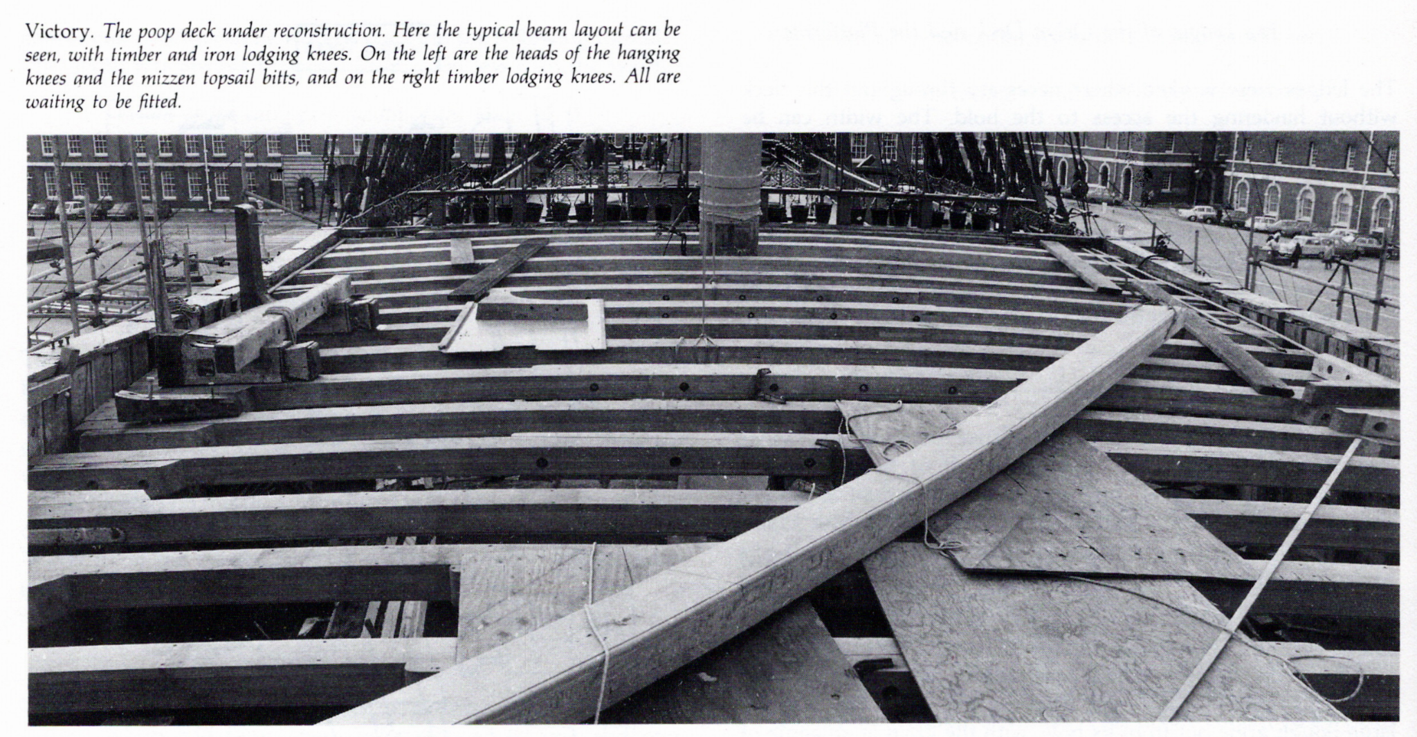
Good Evening Charles; Thanks for your post, which gives a modern point of view, and sounds reasonable enough. The degree of distortion of the fair curve in the sheer of the deck, which would only be noticeable at the extremities, most notably the bow with its rapid narrowing in width, would be dependent upon the amount of round-up required on each deck: the greater the round-up, the greater the distortion. I suspect that the practice in earlier days may well have been that all the deck beams in the midships, and probably going right into the stern, were cut with a constant camber. Coming into the bows, except where a downward curve to shed water may have been desirable, the amount of round-up could then have been increased to provide a fair sheer, which would have been a fairly simple exercise for any competent craftsman. Re the query concerning 'elastic' properties, this is only truly valid if we are talking about a monolithic deck covering, for example a large sheet of ply. As decks were made up of individual planks, all shaped to fit against each other, there is more than sufficient elasticity provided by the construction method used. Below is a photograph of the poop deck of the Victory during restoration, taken from Peter Goodwin's book, The Construction and Fitting of the Sailing Man of War 1650 - 1850. The deck beams all appear to be arcs of circles, and to be of a constant camber, demonstrated by the fact that all the edges appear to be parallel. The best proof of this, of course, would be to ask someone who worked on her, which I may be able to do. The actual amount of curvature does not appear to be very extreme, and it must be borne in mind that the poop deck of a sailing warship had the greatest amount of round-up of any of the decks; so all other decks would have a lesser camber than is shown here. All the best, Mark P

-
Thanks Druxey; That's all wonderful work. To be recognised as a master-carver, as Gibbons undoubtedly was, at a time when there was so much carving being done for so many buildings and objects, and therefore so many carvers everywhere, he must have been really, really, special. This is obvious in his work, which can be found in so many of England's great houses; but I was not aware that he had done so much in St Pauls. Thanks for posting this. I would really like to have heard the conversation(s) which must have taken place when Evelyn first came across Gibbons, and realised that he was beyond the ordinary. When I can carve as well as his less famous contemporaries, I will have achieved all that could ever be reasonably expected. Gibbons will always remain an aspiration beyond reach! All the best, Mark P
-
Good Evening Dean; Thanks very much for the well-explained clarification. Both the methods you describe have been used to draw arcs/curves for shipbuilding. I have to admit that I have no certainty as whether an arc or an ellipse results from the second method. I will set this out in CAD and see what results. I would be very dubious about the deck beams being elliptical though, for the following reason: using arcs of circles, the curvature stays the same, and as the beams shorten, the actual rise, or round-up in the centre lessens. This means that only one template is required for the curvature, which can be used for all the beams on each deck. If we start talking ellipses, then a different template would be required for each beam. Which would be both a lot more work, and lot more timber for making templates. Which I would think also answers Stuglo's question above. Although that said, the difference between an elliptical curve, and an arc, can sometimes be very small. I remember setting out an elliptical stair once, using AutoCAD's ellipse command, which resulting shape I superimposed on an 'elliptical' shape drawn to two radii given by the architect, with a short, mirrored arc forming both ends of his ellipse, and similar arcs to a larger radius forming the longer sides of the ellipse. With the lengths of the long and short axes of each shape matching the other, the difference between the outlines of the two shapes two was hardly noticeable. I will do a bit of setting out, and let you know. All the best, Mark P
-
Good Morning Jaager; I have never heard that the deck beams are curved elliptically; can you remember your source for this? Is it for American ships only? All I have ever seen stated is the amount of 'round-up' to be provided at the midship beam, which varied according to which deck it was. Interestingly, in the restoration Navy, the deck beams were not parallel top and bottom, but were thicker in the centre. All the best, Mark P
-
Good Evening Vladimir; I am glad to see that you are putting what you learned with your Cutty Sark to good use in a new model. At a smaller scale, too, so it will be easier to handle. It's all taking shape nicely, keep up the good work; I will watch with great interest. I wish you much joy from the building, and even more joy looking at the completed model for many years to come. All the best, Mark P
-
Good Evening Don; Can you confirm your source for the dimension of your carlings. They should be considerably larger in section than the ledges. They look far too flimsy to me. I understand that this is a hold platform, and so may be different, but please check before you make much more. Some platforms only have beams, to allow the removal of the deck planks to access the hold below. All the best, Mark P
-
Good Evening Dave; Another guide to size is calculated from the circumference of the shroud. The diameter of the dead-eye is one and a half times the circumference of the stay or shroud. The thickness is slightly more than half the diameter. Interestingly, early rigging inventories call these 'deadman-eyes'. Which makes the origin of the name clear, albeit rather macabre. All the best, Mark P
-
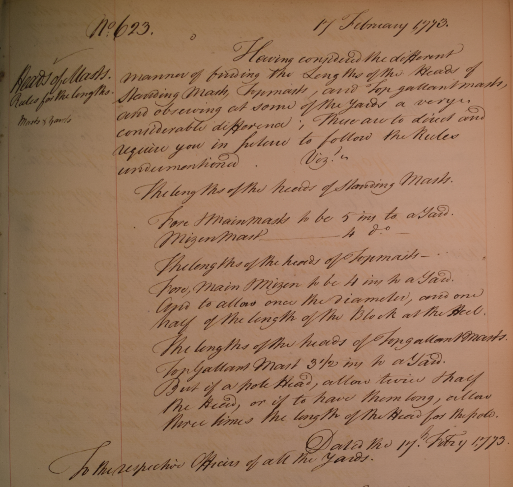
Good Evening gentlemen; Good work Allan; congratulations on a thorough working to find a definitive answer. Though it would seem that the length of the masthead was not a hard and fast matter, even as late as 1773. See extract below, taken from a contemporary letter book. This gives the Navy Board order to regularise mast lengths in accordance with various multiples. However, it is stated that this has been done because wide differences have been found. The ideal measurement was obviously not always achieved/known/complied with, for whatever reason. Contemporary documents relating to the Royal Navy in the 17th & 18th centuries do not, unless my memory is completely failing me, ever talk of hounded length when describing the calculation of mast lengths; only of mast length. Which we can take to be, as Allan has demonstrated so well above, the overall length of all parts together. The NMM has a good number of careful scale drawings of contemporary masts from the last quarter of the 18th century, which give a lot of detail of the construction and appearance of a warship's masts. There are also a multiplicity of contemporary documents, stretching as far back at least as the reign of Elizabeth I, which give mast and yard lengths for a great variety of vessels, by rate or by individual names. It is often possible to find the sizes for a desired ship amongst these. All the best, Mark P
-
Good Morning Phil; I am somewhat confused by the proportion given above of 0.166, as this does not seem to make any sense. For example, a 12" mast, multiplied by 0.166 = 2", which, if this is the circumference, will require a rope only 5/8" in diameter. I cannot believe that any mainstay for a 12" mast would be this size (unless it is wire?) As a check, the mainstay of late 17th century Royal Navy warships had a circumference which was close to 0.5 the diameter of the mast. So a 24" mast would have a stay of approximately 12" circumference, giving a stay of 3 3/4" diameter. This is approximately 15% of the mast diameter, not 5%. Can you clarify this in any way, as something is clearly amiss. Your earlier posts, and all your work, on schooners is all so thorough, that I can only suppose that you have had a moment's memory lapse when giving the proportional figure above; or the explanation is in error (or that I am!) All the best, Mark P
-
Bow & Stern blocks
Mark P replied to DaveBaxt's topic in Building, Framing, Planking and plating a ships hull and deck
Good Evening Dave; I would see no problem with using blocks of fairly thick ply between the bulkheads at bow or stern. If you use too many, the model will become quite heavy, but thick ply will give you enough material for creating some compound curves, and avoid the risk of leaving it too thin at the edges. If you use normal timber, especially softwoods, you run the risk that it will shrink unless thoroughly seasoned before use. So if using softwood, keep that in mind, and choose the oldest stock you have. Re your troubles with the keel, all ply will warp if allowed to/forced to. As you have become aware the hard way, it is best to restrain it in the desired shape, as well as you can. But that is good practice with whatever material one is using. All the best, Mark P -
Bow & Stern blocks
Mark P replied to DaveBaxt's topic in Building, Framing, Planking and plating a ships hull and deck
Good Afternoon Dave; Plywood is a very dimensionally stable material; at the scale sizes at which you would be likely to use it, movement would be so small as to be not worth worrying about. That said, though, the veneers of which it is made would probably absorb moisture from a very damp atmosphere, and would expand if this happened. Depends to some extent on the number of veneers and the quality of the glue used. The greater the number of veneers the better quality the ply, generally; but also the greater expense. However, if you can obtain off-cuts of decent quality, thick ply from a local joinery shop, these would probably make good filler blocks. Avoid shuttering ply: this warps like a live thing! If using sections of timber of any size, remember it shrinks across the grain; ie a plank 6 feet long x 6" x 1" will reduce across the 6" by up to a quarter of an inch if newly sawn; and across the 1" by a small amount; but the length will remain at 6 feet. The other factor is that the end-grain of softwoods will show a pattern of curved lines, depending upon where exactly it was cut from the log. These curves always try to straighten out. Fixing into end-grain is generally considered to be the weaker fastening method; and most modellers seem to avoid it. The best advice is to be sure to use wood which has lain around for as long as you can manage to leave it. All the best, Mark