Mark Pearse
-
Posts
840 -
Joined
-
Last visited
Content Type
Profiles
Forums
Gallery
Events
Everything posted by Mark Pearse
-
 Hi Mike I coated a new timber floor (2nd hand Australian hardwood) with pure Tung Oil, so no thinners, no resins etc - sounds the same product that you have used. We did one coat, it was spread fairly thickly, really wet, then about an hour later the excess was wiped off. No walking for 24 hours, & the result was good. I have also coated a plywood floor the same way, that time using multiple coats which did build up but at times didn't seem to be setting. They both cured, but it is different to other finishes & didn't feel dry in the way that a polyurethane finish feels dry. It does sound like yours isn't curing - my understanding is that it cures in the same way that boiled linseed oil cures, a chemical reaction, so you must not bundle up rags that are soaked in the stuff, it releases heat in the reaction & can ignite. So I'd be careful about diluting without checking my recollection that it cures rather than dries, & also that it will still cure if is diluted... On the question of a satin finish, with furniture I often do my build up coats & then as a final coat let it half dry & then wipe it off with a rag to give a greasy look, it replicates the finish that wax polish that hasn't been buffed has. Hopefully this helps, best wishes. Mark
 -
thanks, I'll give the model an upgrade to residential class & see how we go....
- 7 replies
-
- 2
-

-
- paint
- drying time
- (and 1 more)
-
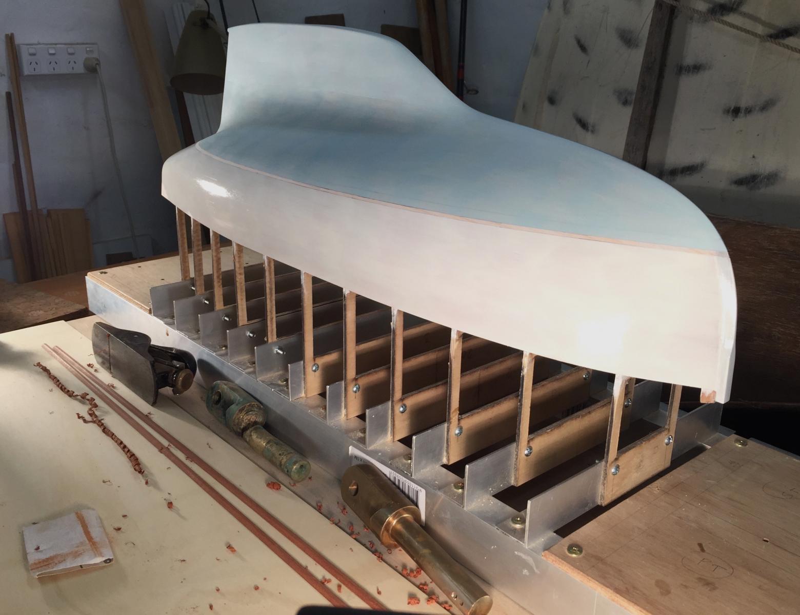
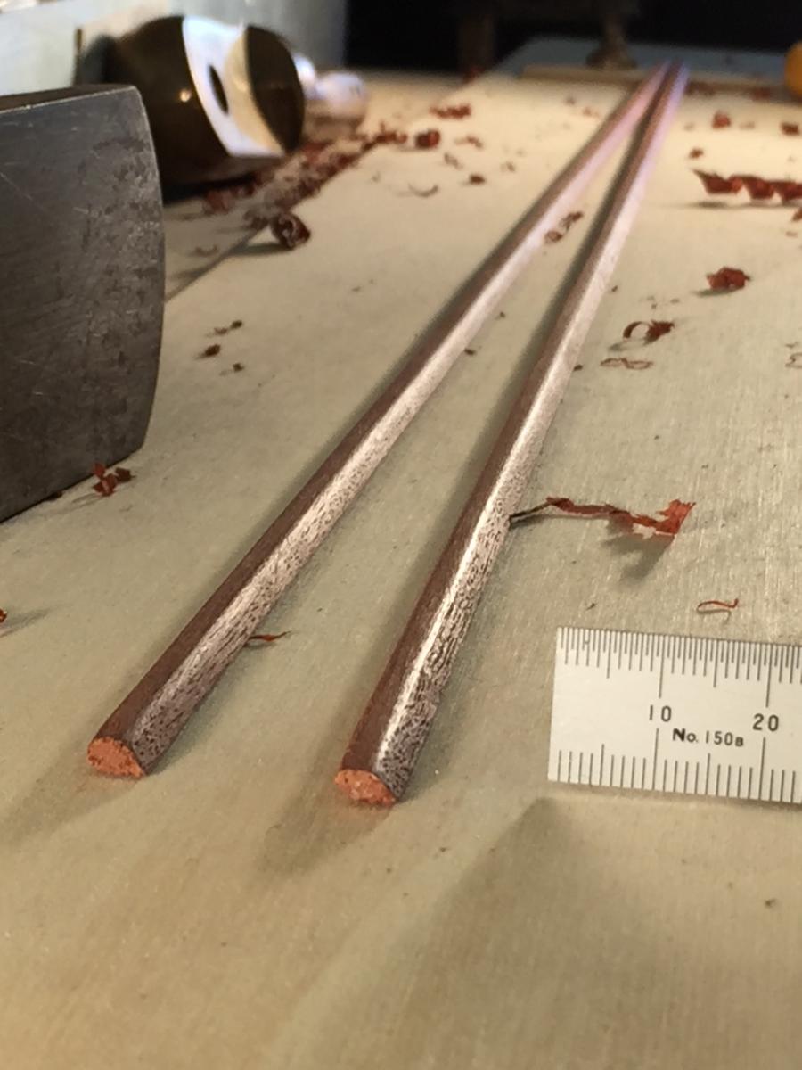
first coat of paint, I want the topsides to be more cream, & the antifouling a bit greyer rather than blue/grey; otherwise I'm happy as a pig in mud I like the way you can see a few planking joints, appropriately the garboard seam is quite visible, considering how much grief this seam gives the boating world The new & old broken gooseneck pin for our 24' foot boat is visible - it's extraordinary what effect a 1:12 scale change has, this fitting would also suit this boat transom (used to be called the tuck in Sydney) the sponsons - or lower gunwales, shaped from native Rosewood, I' considering shellac as a finish bye for now, thanks


-
Hi everyone I did a first top coat in a mixture of Humbrol gloss enamel colours (3 tins, 2 of one colour, one of another), didn't add any thinners or anything else; it was done over a thin coat of Zinser oil based undercoat that had been well sanded & was well dry. The Humbrol took ages to dry - almost a week so far, it's still not dry enough to sand but it is close. It was very nice paint to use & the finish is good, despite the gradual accretion of dust over the week.... My 'workshop' is a cool garage, not really damp & not really cold, maybe 17 degrees C & things don't go mouldy there. Anyone comments? My thoughts are that I just need to do the next coats in a warmer location, but I am surprised that it took so long. thanks in advance, MP
- 7 replies
-
- 3
-
-
- paint
- drying time
- (and 1 more)
-
more to learn indeed, thanks all
-
thanks very much everyone, quite a bit to think about & try out there. I like the sound of the self-tinning solution. Michael, I never considered using stainless steel - will it braze?
-
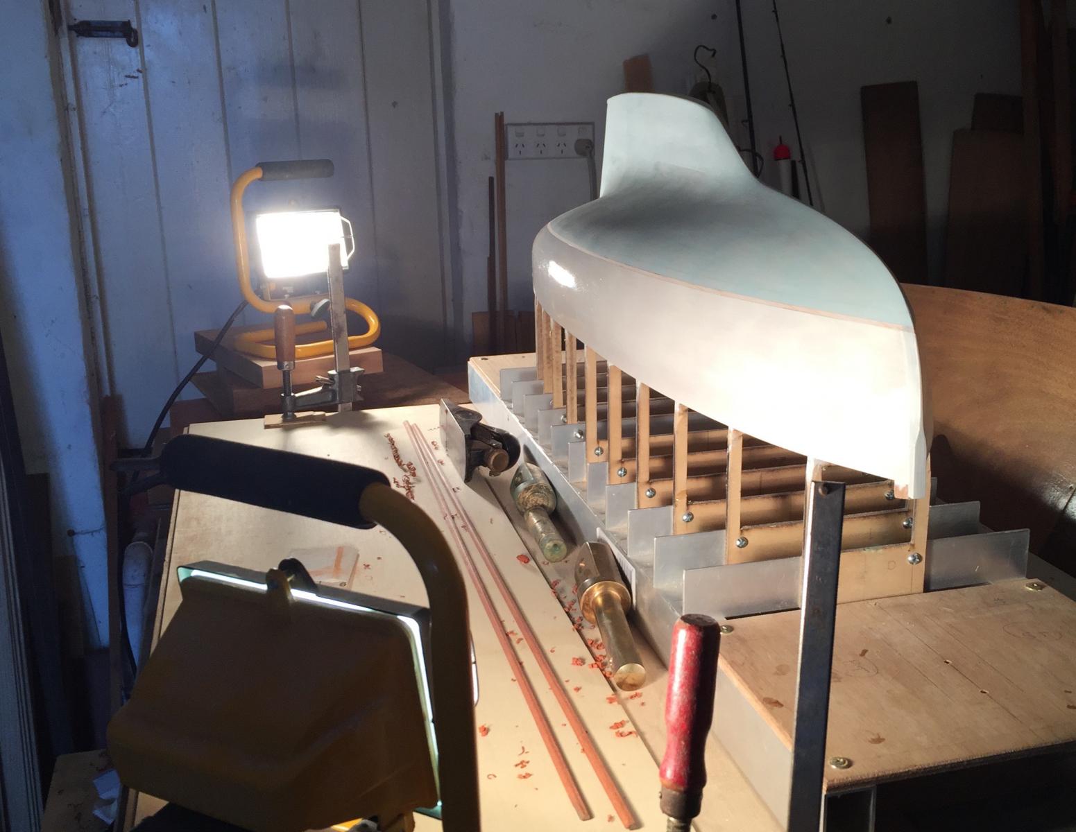
Hi Patrick, I've been doing something similar: two 100w linear halogen work lights for about an hour yesterday & today, they give off a gentle warmth & the paint is close to dry now. thanks Mark
-
g'day Patrick, I've done some topcoats - no photos yet though. It's amazing how the painting is making sense of the hull shape. I've used Humbrol enamel & it's taking a long time to dry...it's nice paint to use & the finish is good, & I know my 'workshop' is actually a damp cave that would make Gollum feel cold & lonely, but it's been about 4 days & it's still tacky. Mark
-
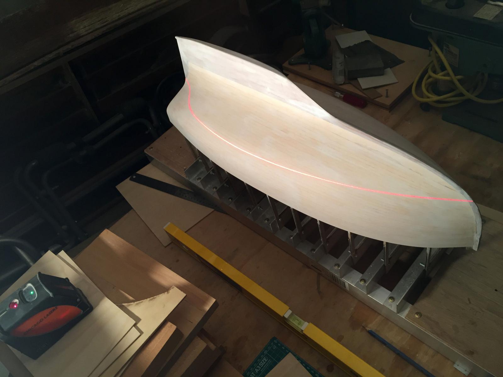
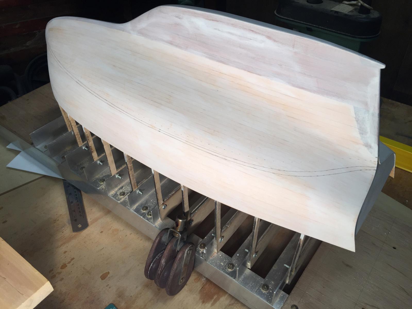
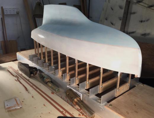
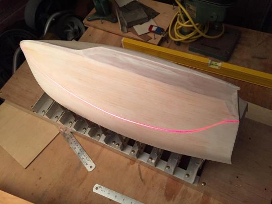
I've undercoated the hull & set up the boot top line, using a laser level to get the waterline & then adjusting the model height & angle to get the boot top lines. I marked the waterline in 6H pencil, added 50mm (scale) height slightly aft of the middle for the lowest point of the boot top line, which is increased to 100mm at the bow & 65mm at the stern. The boot top line width is 30mm scale width at its narrowest, 50 at the bow & 40 at the stern. I like the way lines added on to a hull shape improve its appearance - or maybe its truer to say that they explain or show off the shape. The artist Christo had the same idea: a curve is hard to see, but put a line on it & your eye looks at the curve of the line. I'm hoping to do some colours in the next week. One minor issue has been that the Titebond glue resists sanding more than timber does, so when you have an internal corner with dried glue in it, it's difficult to sand cleanly. On the hull sanding, I am accepting some visible joints in the timbers, especially in the keel. I think it's consistent with the probable construction standard of the yacht - if she had been built in the 1930's or 40's. I will fill some of them a bit, but I'm not planning to make the model look perfect. thanks all, bye for now MP painted & sanded waterline waterline the waterline & boot top lines in pencil


-
I agree with David, the chine wasn't out enough to be visible so it's worth considering accepting that minor issue. There is the personal question of just how much rebuilding we are each happy to do & not be discouraged. Mark
-
Very nice, a boat with an almost living spirit. What is the square tin with a timber handle set into it? It looks to have a particular use. Mark
- 83 replies
-
- 3
-
-
- sponge boat
- finished
- (and 1 more)
-
Hi everyone, the yacht model I'm building would have mainly stainless steel fittings. Can anyone recommend a way of replicating the pale grey finish of SS on a brass part? I know that SS is really a silver, but at a distance - & especially on a used boat - it tends to look more grey than shiny silver. Any thoughts? thanks, Mark
-
Tool for Shaping Brass Strip
Mark Pearse replied to mikiek's topic in Metal Work, Soldering and Metal Fittings
Hi Mike I wonder if you cut a v out of the inner side of the corner, most of the way through, then folded it at that point....it would give a sharper corner & also hold itself in position for the soldering/brazing. best, Mark -
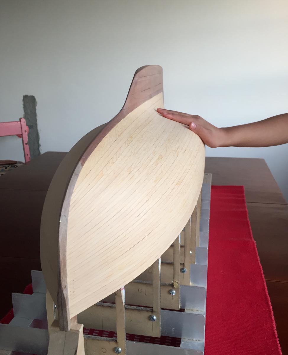
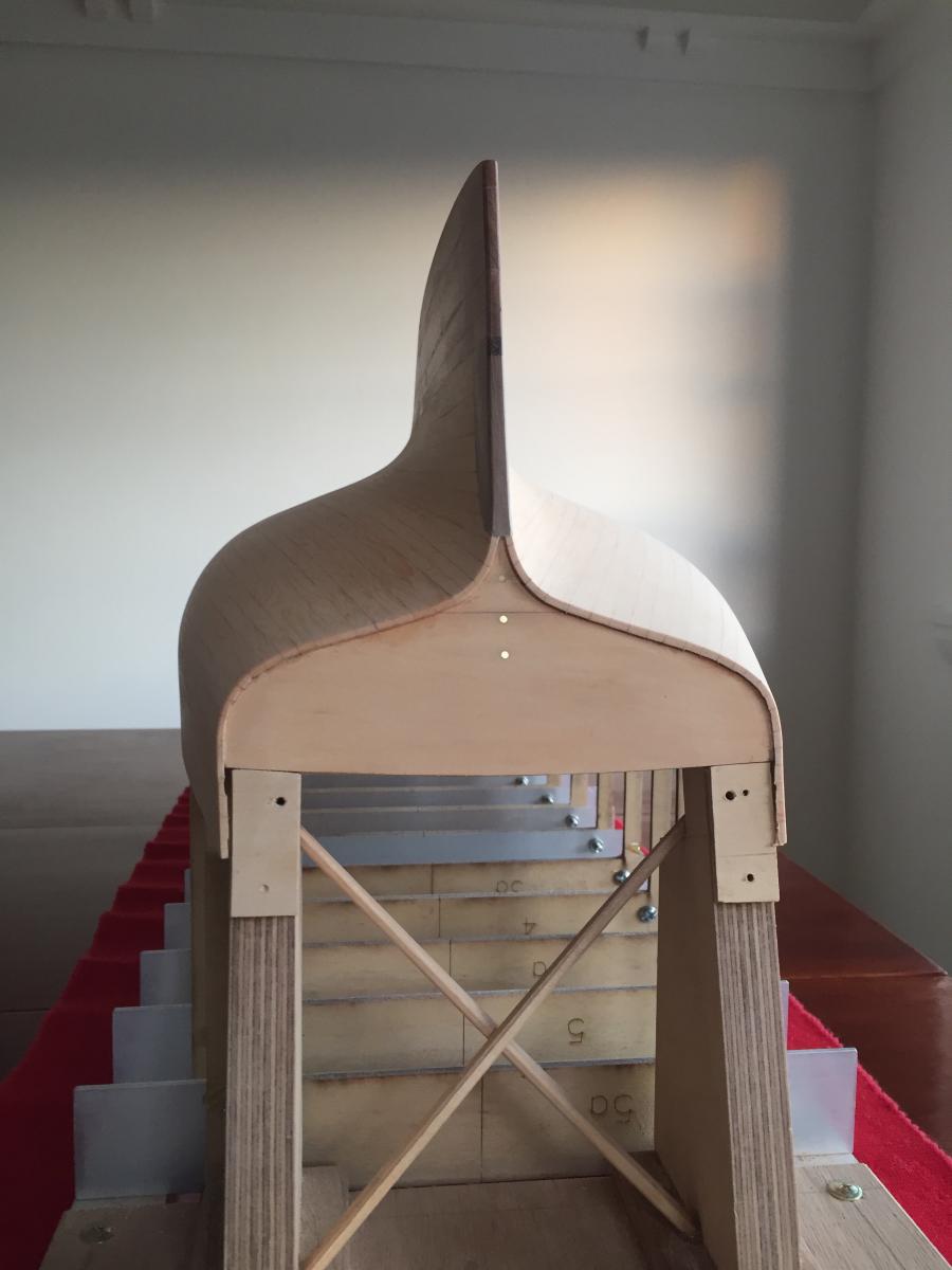
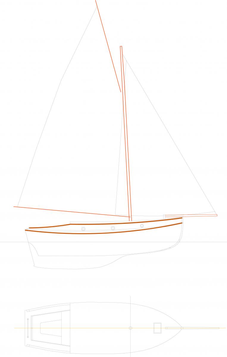
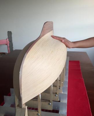
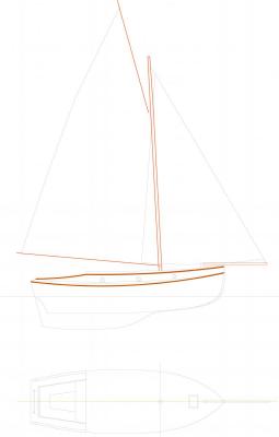
I've been sanding the hull, there's still some detail sanding to do but it's now almost done. I may paint the hull while it's still on the frame, it will be easier to do the boot top lines this way. It would mean that I can use a builder's self-levelling laser to get a horizontal line, tracing it with a pencil by hand, & then adjusting by eye to suit the right curve. Sanding the inside edge of planking ends at the transom is especially delicate, & needs to be to accurate to give the impression of scale. I have done some of this sanding, but a few more hours of careful work required there. I did have to splice in a strip of planking where the garboard was down too low. In any case I need to place the mast, & the drawing son the design do not include any information on mast setout, spar sizes etc. I've sketched the sail plan below, which is based on the sailplan of the 24 footers, plus just my eye - for better or for worse.... I've noticed that there's a lot of different ideas about the gaff angle - this high peaked angle is typical here, you almost never see a low peaked gaff that seems to be popular in America. I believe that sail twist would be greater with a lower peak angle & especially with cotton sails, so I wonder if they used gaff vang lines from the peak of the gaff spar to the quarters - to control the twist...but that's another conversation. I also had another go at the line of the sponsons - the lower gunwales - & I've put more bounce into it. See the brown lines on the drawing. I probably rushed into a detail drawing before when a broader view was still needed. I'll sit on that one, & will do temporary ones when the time comes, to see how they look.
- 411 replies
-
- 11
-
-
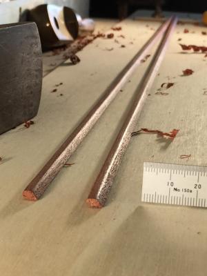
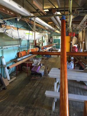
Hi Michael, I saw your question about a gaff mast size. I believe they need to be thicker; apart from the extra power of a gaff mainsail, the gaff spar has a lot of thrust forwards on the mast, a lot of load at one point. Below is a photo of our spars when we revarnished over winter, the mast, boom & bowsprit. The mast is the one on the left running down the shed & the slender unvarnished mast below it is a Folkboat mast, a bermudian mast from a similar length boat to ours. I think you can see the difference, which is slightly exaggerated by being further away from the camera, but standing next to them both the difference is significant. Also the taper is quite different, the gaff mast is tapered only a little up to the spreaders/gaff throat height & then tapers more above that. Above the spreaders, if the aft mast face carries the same line up, & the forward face & sides do the tapering, that looks nice. You can just make that out in the photo. Mark
-
Hi Dan, looks like a lot of enjoyment coming up. For your interest, the design is surprisingly similar to a lovely little boat that was very popular here in Australia, an 18 foot ply boat called a Hartley TS18. A friend used to go away camping as a child with parents, kids & dog in one....must have been crazy. They also sail very well. Best wishes for the build. MP
-
better with the name, so much personality deserves a name
- 83 replies
-
- 3
-
-
- sponge boat
- finished
- (and 1 more)
-
I like the subtlety of the colours for the antifouling, topsides, deck & decking timberwork.
- 258 replies
-
- 5
-
-
- buzzards bay
- herreshoff
- (and 1 more)
-
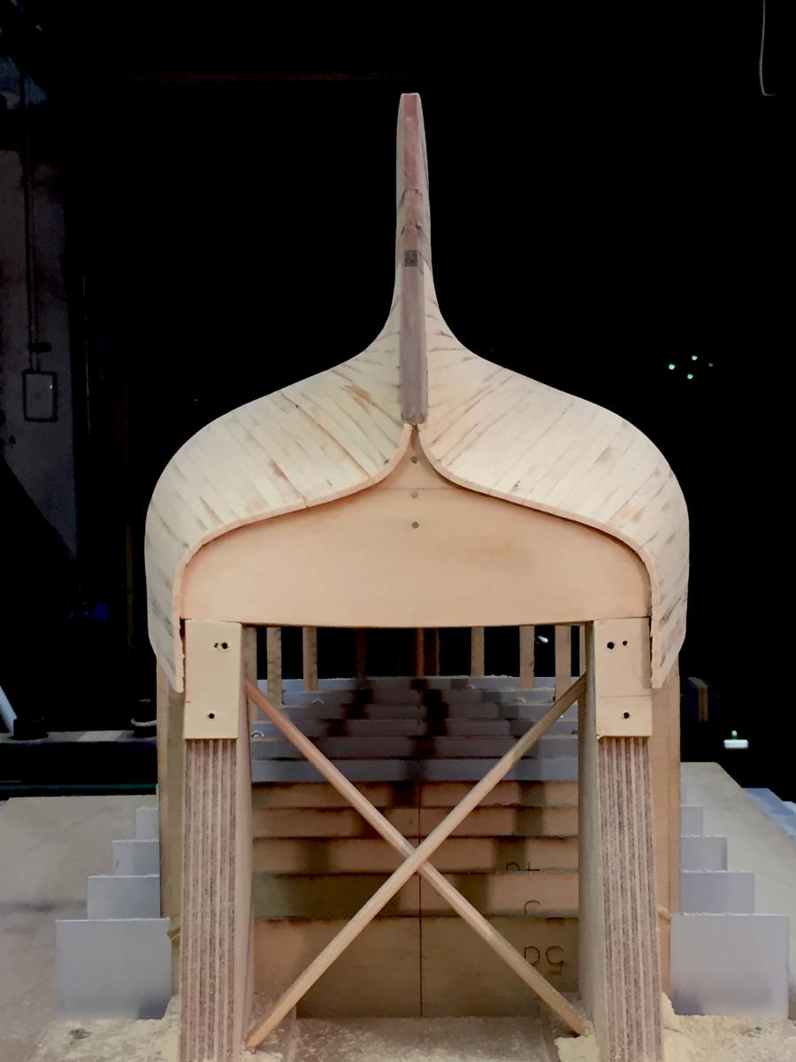
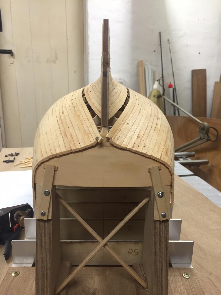
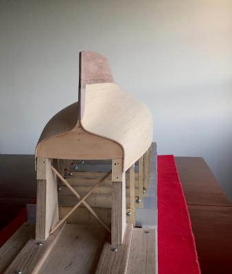
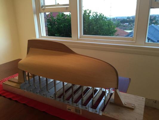
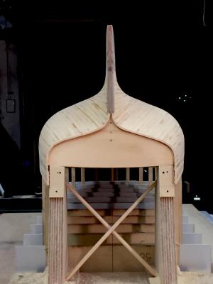
Michael, interesting thoughts - and I did get the idea for this building frame from your skipjack frame. The high moulds did allow manual access, but they did need to be braced a bit as the thin ply was quite flexible. It could be braced in a more thoughtful way than I did it, perhaps tensile bracing... On the planks, they are to scale & tapered based on the set out I did for the hull, & I didn't need to spile them in the way I read about in the planking primers - I think because the Huon Pine is so supple it allowed me to get the wood to the shape of the last plank. When a little twist or lateral bend was needed, I - like I see you did - used a heat gun & clamped the other end of the plank to a bench. There are a few wobbles if you look along the planks, & when painted I think that you will see some evidence of the lines of the planks through the paint, but you won't see enough to pick up the wobbles. A long rambling way to say that the stealers were based on the stealers in the full sized 24 footers. I'd like to do a model with an interior, there's a lot of pleasure in seeing a traditional boat hull interior - to model scale or full scale.
-
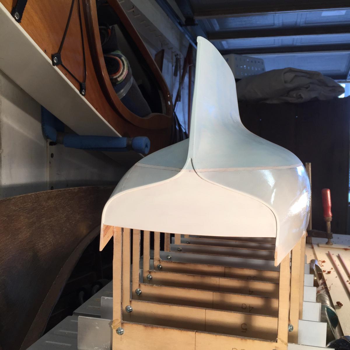
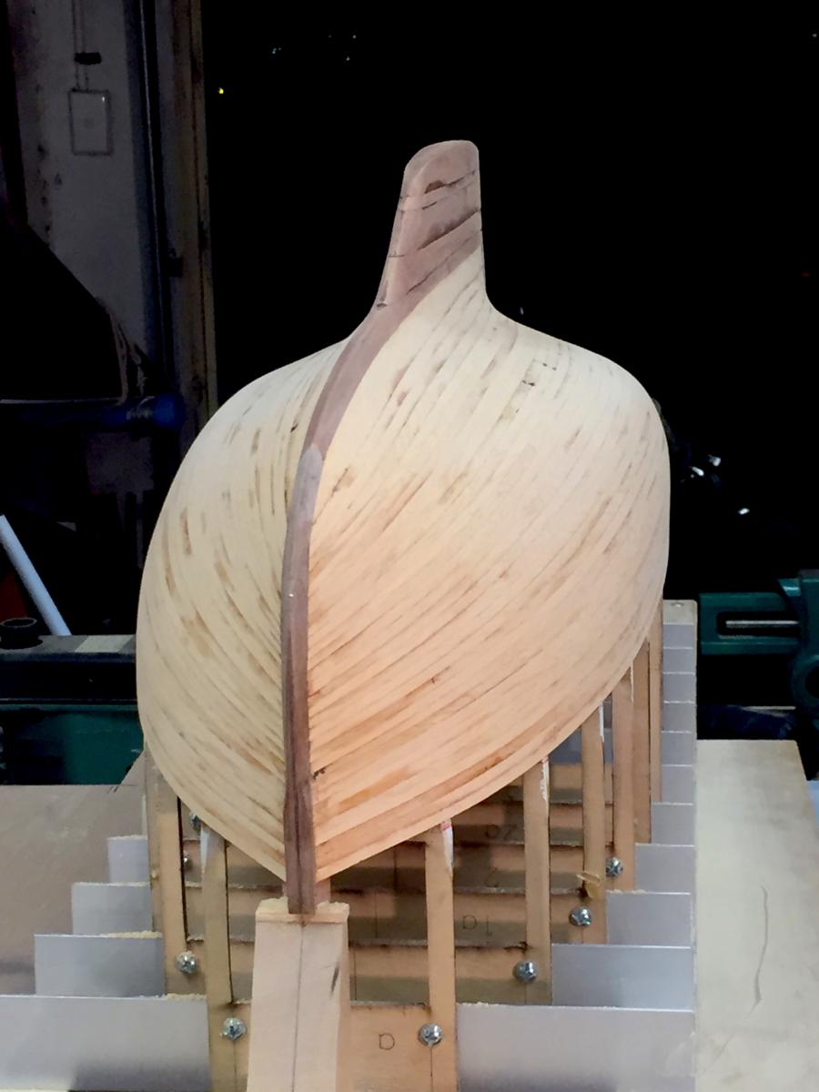
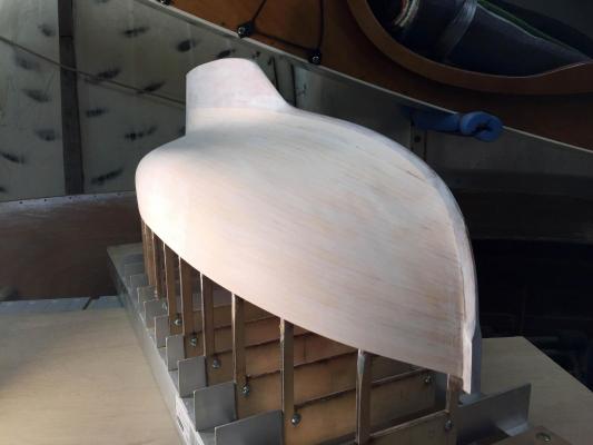
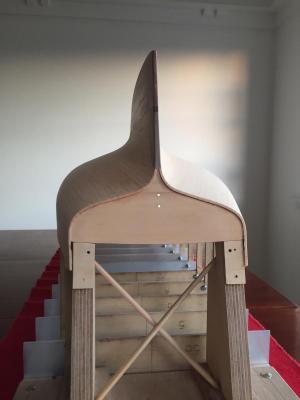
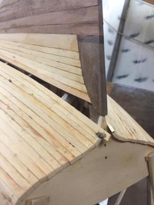
thanks guys, Bedford, I especially like the transom shape, at this stage it still looks similar to Ranger's (first blog entry has photos), but I think that when the transom fashion piece goes on, the planking ends are fined off & the hull sides are shaped to suit the raised deck etc, it will be the prettiest transom in a pretty good looking bunch. Mark
-
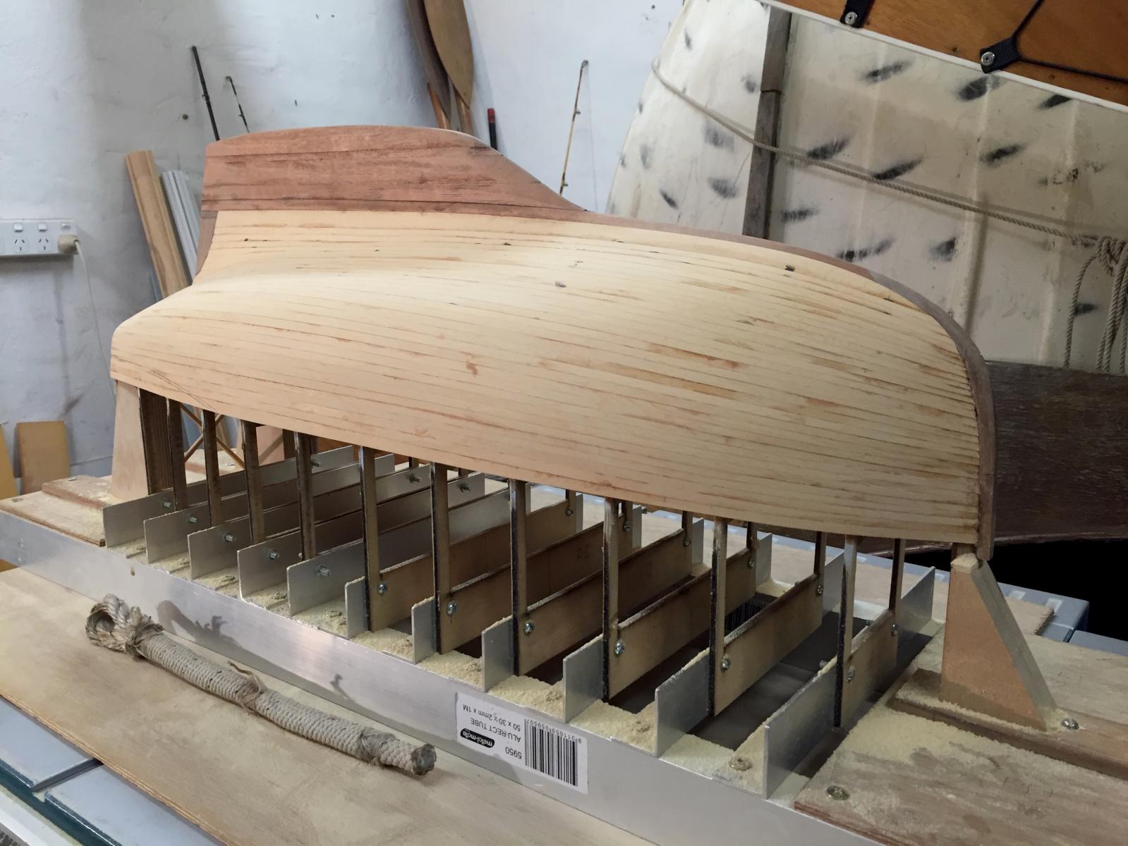
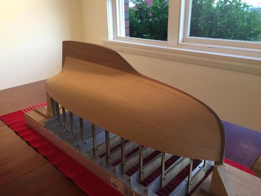
thanks all Planking completed & some rough sanding done. There are some planks where it may be easier to infill thin strips of timber on top of the planks than to sand it all back to the lowest part. You can see in one of the photos that this is the case for the upper edge of the port side garboard plank, the change in colour of the sanding highlights the recess. I think it would be pretty easy to thin down some timber & glue it on. Yes, Michael, I'm wondering about the next few stages...there's always the attraction of doing next the stage that will give the most dramatic visual change, over a more reasoned & sober reckoning. So, after sanding the hull, & probably undercoating & marking the waterline while the base it there holding the hull level, I will no doubt succumb to the most dramatic visual change & do the deck & the basic parts of the cockpit area. The model is still a bit scaleless with no parts to give the eye a reference of size, & I'm keen to get a sense of the yacht's design & feel.
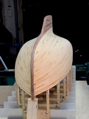
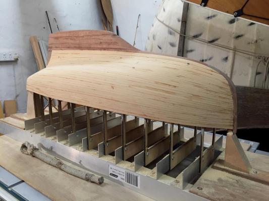
- 411 replies
-
- 13
-
-
Pretty boat, pretty model; hard to believe they are only 14 foot long, a big little boat indeed. Do they ever carry spinnakers?
- 258 replies
-
- 5
-
-
- buzzards bay
- herreshoff
- (and 1 more)
-
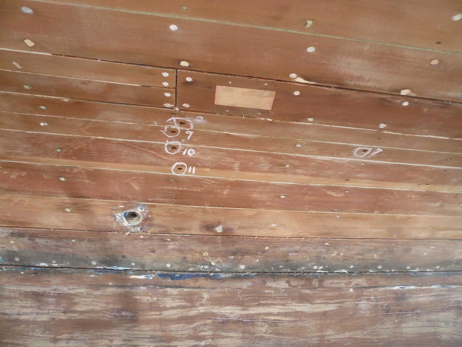
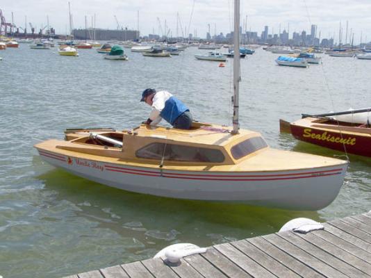
One plank remains & it's the one with a stealer, but when I checked through some photos, it's actually not going to be as difficult as I was expecting. In one of the excellent forum primers on planking, it describes how to do a stealer plank on a ship. But I'm going to do it as in the photo below, from our boat Cherub - you can see where one plank stops & becomes two that take up the extra width further down. So I guess that's how they did it for this scale of boat in Sydney at that time. It will make it a lot simpler too.

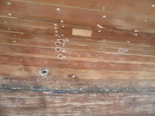
- 411 replies
-
- 12
-