MORE HANDBOOKS ARE ON THEIR WAY! We will let you know when they get here.
×

popeye2sea
-
Posts
1,934 -
Joined
-
Last visited
Content Type
Profiles
Forums
Gallery
Events
Everything posted by popeye2sea
-
 Part #162 are the four large knight heads that go in a square pattern around the mizzen mast. There will be three smaller knight heads (163?) that go in a triangle pattern around the mizzen. One centered in front of the mast and the other two in the holes outboard of the larger knight heads. Regards, Henry I replied before I read the further posts. This has already been answered. Oops!!
 -
I might add that if you look at the gun port lids from the kit there are two rings molded on each for the ropes. They are at the extreme end of each hinge. Regards, Henry
- 1,508 replies
-
- 1
-

-
- Le Soleil Royal
- Heller
- (and 1 more)
-
Topsail, topgallant, and royal square sails do not need tack lines because when they are sheeted home their lower corners are confined to the yards below them. For the lower courses the sheet serves to pull the lower corner down and aft, and the tack serves to pull the lower corner down and forward. Thus both are needed to control the lower corner (clew) of the sail. Hope that helps. Regards, Henry
-
Interesting! I'll have to look for that. Regards, Henry
-
My plan, I have not done it yet, is to not drill all the way through but to make small dimples or partial holes from the outside and then use short lengths of rope or small painted wire glued between the gun port cover and the hole. Regards, Henry
- 1,508 replies
-
- 1
-
-
- Le Soleil Royal
- Heller
- (and 1 more)
-
Reminds me of the eyeglass nose bridge handle thing from Steve Martin in "The Jerk". How many people went cross-eyed from this gizmo? Regards, Henry
-
Not so long ago any respectable man would not be out in public without at least a waistcoat, neck cloth, and hat. Up until the early 1800's your shirt was basically your underwear/night clothes. Regards, Henry
-
I agree with Marc. Heller does this to give an attachment point to each anchor cable. They are totally unnecessary. Regards, Henry
- 1,508 replies
-
- 1
-
-
- Le Soleil Royal
- Heller
- (and 1 more)
-
Bill, make sure that part 266 is well secured in the hull. Your main mast angle will be determined in part by its alignment with the holes in the decks. I took some extra time to make sure the mating surfaces actually made good contact before glue up. I don't think the hull halves meet at a flat angle at that point. Regards, Henry
- 1,508 replies
-
- 1
-
-
- Le Soleil Royal
- Heller
- (and 1 more)
-
I agree with Marc, reinforcing the center seam is a good idea. I am not a fan of the Heller stand. If you do go with pedestals I would highly recommend using something like epoxy to fix a threaded nut into the base to take the bolts of the pedestals. You don't want them to come loose. Mine did and now I have to come up with another plan to secure the model to it's base. It is going to involve further surgery to the keel. Regards, Henry
- 1,508 replies
-
- 1
-
-
- Le Soleil Royal
- Heller
- (and 1 more)
-
If your intent is to show how much potential canvas they could carry then any angle will work. I think your only consideration will be with all that canvas set if you have the yards braced hard up then a lot of your hard work on the rigging will be hidden. Then again if the model is to be viewed from both sides you will have one side with a cloud of canvas and the other exposing much more of the rigging. Personally, I think clippers are beautiful with every stitch of canvas aloft. Realistically, the direction of the wind and its force would determine which of the stun's'ls would be set. If you look carefully at your diagram you can see that some of the forward sails would be blanketed by the aft sails. Perhaps in this instance on the main only the topmast stun's'l to leeward would be set. Regards, Henry
-
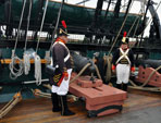
My profile pic is me next to a carronade on the spar deck. I hesitate to post all that stuff here because it doesn't really fit the MSW profile. But, visit us at www.1812marines.org or our facebook page USS Constitution 1812 Marine Guard for tons of photos of our group in action. Regards, Henry
- 1,508 replies
-
- 1
-
-
- Le Soleil Royal
- Heller
- (and 1 more)
-
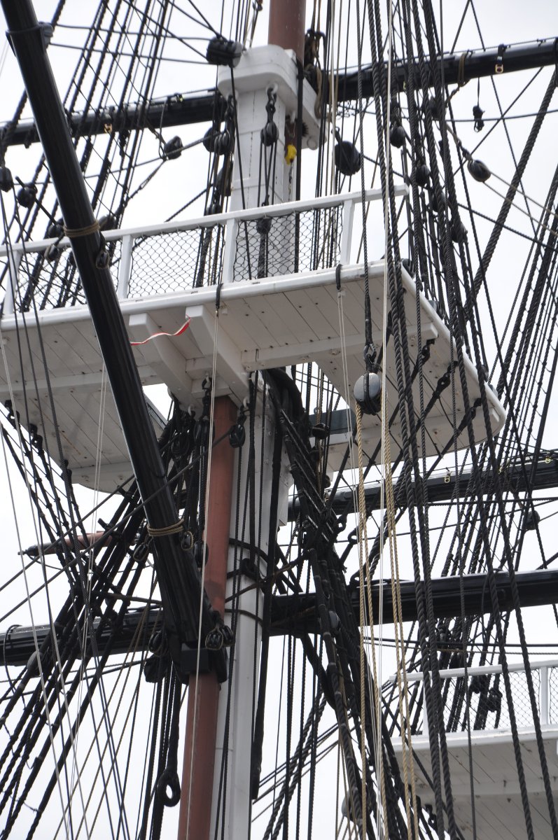
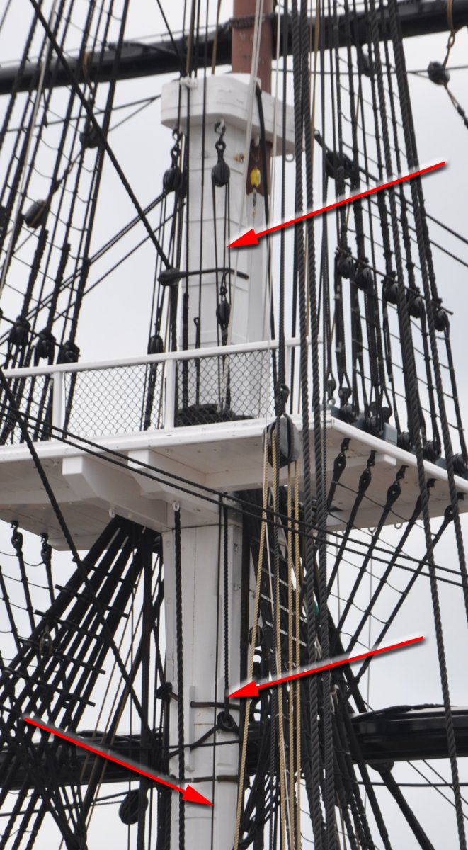
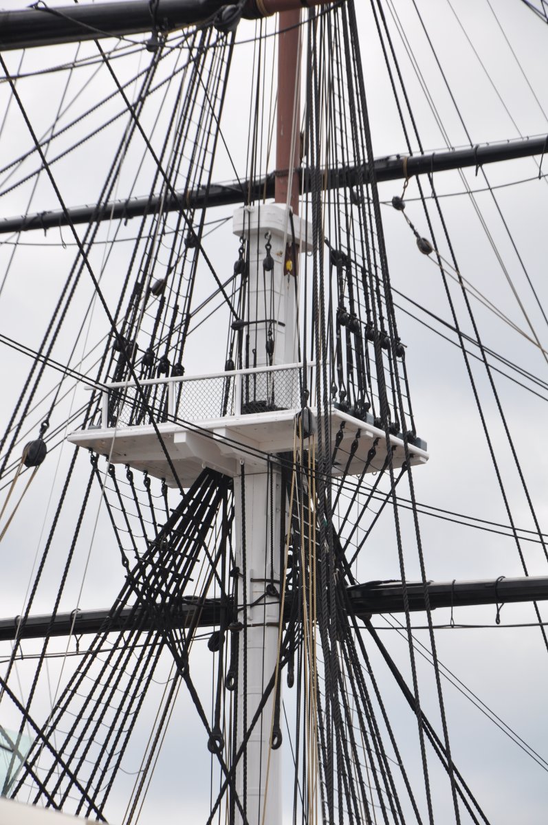
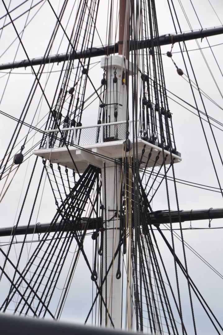
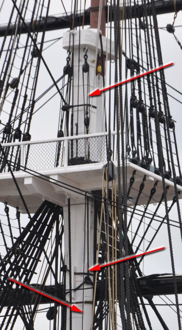
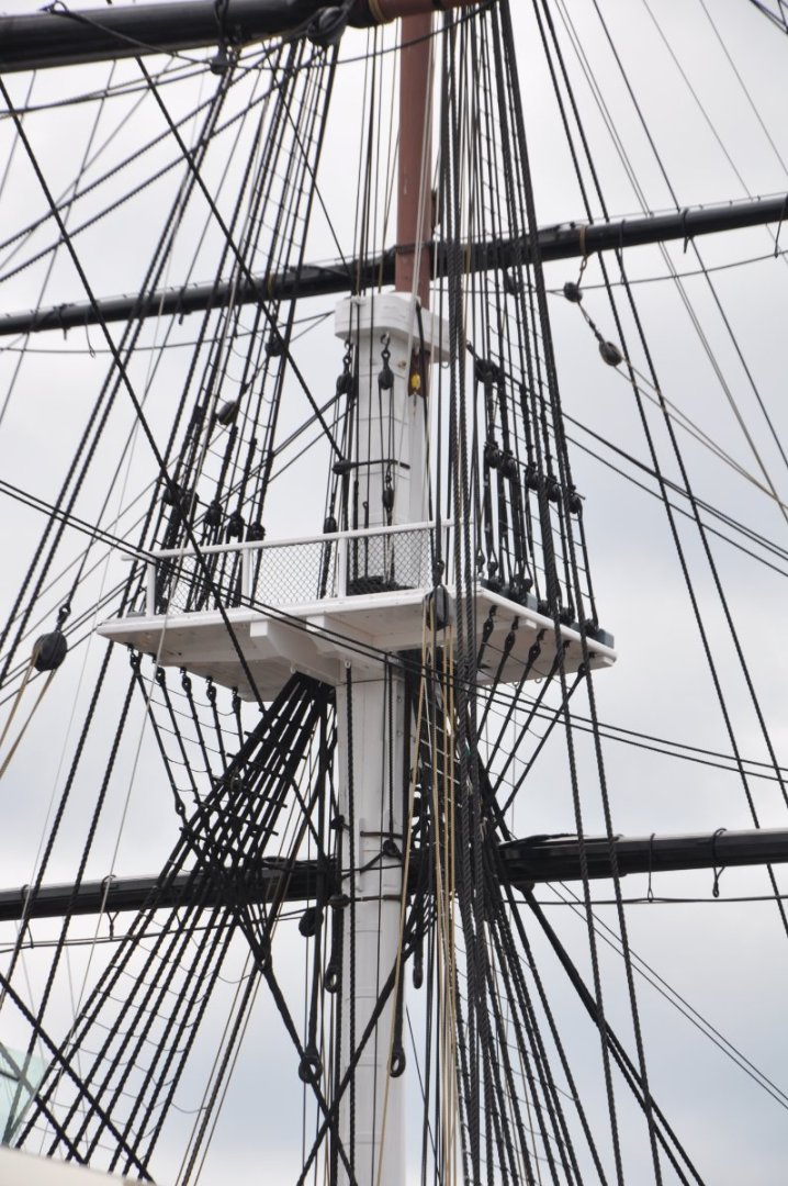
I found my photos of the truss pendants and tackles for Constitution. Hope they help.

- 163 replies
-
- 4
-
-
- Model Shipways
- Constitution
- (and 2 more)
-
I did build the Revell Constitution many years ago. Long before MSW. But that model was lost, foundered in a storm of cleaning by the Admiralty Board (mom) while I was still a young lad. I have another one on deck, waiting to start construction. I am thinking of kit bashing to her as launched configuration. Regarding popping aboard for reference photos, I do that all the time. I have even done it on request for MSW members. Regards, Henry
-
Luis, Studding sails are rigged behind the regular sail on the windward (upwind) side and in front of the regular sail on the lee (downwind) side. The idea being to avoid the principal sail being backwinded by the air spilling off the studding sail. This rule was generally followed by merchant ships. Some naval vessels set stun's'ls abaft all. Regards, Henry
-
Bill, I am the current President of a non-profit corporation called Historic Marine Education, Inc. We represent/portray the marines who would have been aboard Constitution during the war of 1812. The active duty Navy crew aboard the ship consider us to be part of the crew. We are aboard regularly throughout the year to give demonstrations and interact with the public. The ship conducts about six sailing demonstration per year out in the harbor. I have been underway on every one of them for the past 10 years or so. It never gets old. I'll probably continue to sail Constitution until I can no longer make it up the gangway. Regards, Henry
- 1,508 replies
-
- 3
-
-
- Le Soleil Royal
- Heller
- (and 1 more)
-
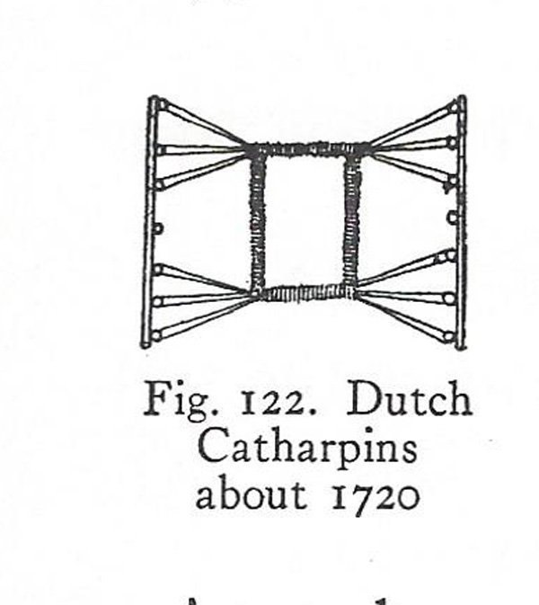
R.C. Anderson has this image. He has very little information regarding the practice for non-English vessels except for a few Dutch references. Regards, Henry
-
The usage of the term jig in this instance is short for jigger tackle, which is a type of tackle arrangement. Usually it refers to a single and a double block, both stropped with tails. The tackle that is used to extend the stuns'l booms does not, as far as I know, have a distinct name other than you can refer to it as whatever it is being used for. To explain. This tackle used to haul out the boom would be termed an outhaul in this usage. But, the same tackle, by shifting its attachment point is also the inhaul tackle to bring the boom back in and the tricing tackle when employed to lift up the inner end of the boom to give better access to the men on the foot ropes while furling sail. With regard to my reference to a cleat, in the diagram above there is a cleat with a sheave let in attached to the outer side of the trestle tree. The diagram shows the truss tackle pendant being re-directed up towards the top around those sheaves. If you rig the pendants as I described above in my post the pendant gets re-directed upwards as it passes through the thimble of the strap around the yard. Thus the pendant will run fairly straight up and down to the tackle under the cap and the additional cleat/sheave is not necessary. The crossing over of the pendants abaft the mast is what pulls the yard in to the mast. Regards, Henry
- 163 replies
-
- 1
-
-
- Model Shipways
- Constitution
- (and 2 more)
-
Yes, the barrel did drop a bit. But the change was not large enough to make any difference in the placement of the guns in the ports. Regards, Henry
- 1,508 replies
-
- 1
-
-
- Le Soleil Royal
- Heller
- (and 1 more)
-
On mine I shaved off the raised trunnion supports completely and carved a new semicircular bed for the trunnion. I added cap squares made from black paper on top of the trunnions. I also moved the trunnions back a bit on the cannons by shaving off the trunnions then pushing a small brass rod through holes I drilled through the cannon in the appropriate spot. I did not end up moving the wheels for most of the cannons because I already had them assembled and they were going into the lower decks anyway. I did change the ones that were going to be visible on the upper decks. Regards, Henry
- 1,508 replies
-
- 2
-
-
- Le Soleil Royal
- Heller
- (and 1 more)
-
The labelling of these are wrong. The blue are jeers. They are actually what are doing the heavy lifting of the yard. The green is the sling and it is in effect the preventer for the jeers so that the yard does not fall if the jeers are severed in battle. The red are the truss tackles and they function to pull the yard in close to the mast. The truss should be rigged as follows: Two straps are fitted around the yard, inside the cleats, with large thimbles to pass pass the truss pendants through. The truss pendants have an eye spliced in the end. The pendants are passed around the yard inside the cleats and through the eye. The ends are then passed abaft the mast and through the thimble of the strap so that the port pendant passes through the starboard strap thimble, and the starboard through the port thimble. In the upper end a block is turned in, which is connected by its fall to an eyebolt under the cap. The fall may or may not come down to the deck. Sometimes it was belayed in the top. That cleat with the sheave on the trestle trees is not used for the truss pendants. Regards, Henry
- 163 replies
-
- 1
-
-
- Model Shipways
- Constitution
- (and 2 more)
-
I think those marks are intended to represent the extra planking put on as a sort of fender or rub strake for the anchors. I know they have a name but I do not recall what they are called. Regards, P.S. I just remembered......Anchor Lining. And the Heller instructions call for painting the area forward of those lines black. Regards,
- 1,508 replies
-
- 1
-
-
- Le Soleil Royal
- Heller
- (and 1 more)
-
Lowering the yards for reefing or shortening sail is a totally different animal than striking the entire yard or setting a sail flying by bending the sail to its yard on deck and hoisting the entire yard aloft from the deck or the top. Sending the entire yard down was usually reserved for upper yards only (topgallants and above). Topsail yards being far too heavy to allow this procedure. Reefing or shortening sail by lowering the yard along its mast is a holdover from the days before reef points and foot ropes. Under the older method to shorten sail you lower the yard and then unlace the bonnet from the bottom of the sail. With the newer method the reef band is pulled up to the yard and gathered under the yard. This is the direct cause for foot ropes coming into use and also is the reason the lower yards (courses) were no longer lowered at all and remain at a fixed height. There are also the additional benefits of reducing top hamper and easier access by the crew as mentioned by others above. Regards,
-
Fashion a loop at the top that will accept a toggle and splice in a toggle an inch or so below the flag and you have an authentic flag ready to be bent on to your halyard. Well done. Regards,