
Marcus.K.
-
Posts
230 -
Joined
-
Last visited
Reputation Activity
-

 Marcus.K. got a reaction from thibaultron in Flag with ship name reversed on one side?
Thanks Bob, for that very intersting insights.
Any idea about the year that New Bedford Flags Signal Flag "Poster" was done?
-

 Marcus.K. reacted to James H in 5 Cylinder Radial Engine (TECHING) - EngineDIY
Here is the main event! The model is actually quite large and weighty, and we haven't finished yet. The ejector rods and sleeves are now to be fitted. This is done one cylinder at a time, and needs to the rocker arms to be lifted to allow the ejector rods to sit.
The base is now fitted, and a spacer mounted between the base and engine. Once fitted, the battery charger port, switch and motor cables are threaded into the base. The cables are then plugged into a control board, along with a battery pack. The circuit is then screwed into the base and a cover fitted to hide it all. The kit also includes a USB charging cable too (not shown).
COMPLETE!
And here is a video I made of my review build.
The instruction manual is clearly illustrated and the average builder should find zero difficulty in following each stage.
Conclusion
I didn't know what to expect before seeing this kit in the flesh, and I was very pleasantly surprised. I'd had a hankering for building something like this for a while, but I suspect the mixed reviews I'd seen were from cheap copies. This kit very much surpasses my expectations in presentation, quality, and also the final result. This model took me about 5hrs to complete, but that's also because I was setting up photos of each stage. I think it's fair to say that the manufacturer expectation of about 3hrs is reasonably accurate. The instructions are very easy to follow and should present no problems, even to a beginner who has no sort of modelling or engineering experience. All parts fit perfectly together with no issue. The only things I would criticise are the hex keys which are a little soft and round off easily, making tightening the screws hard. Also, there is no lube in this kit any longer, so you will need to source your own. In all, a fantastic kit.
My sincere thanks to EngineDIY for sending out this kit for review on Model Ship World. Whilst not marine-related, I'm more than sure you'd really enjoy this one. To buy direct, click the link in the header of this topic.
-
 Marcus.K. reacted to James H in 5 Cylinder Radial Engine (TECHING) - EngineDIY
If you see any black flecks as are visible here, these are just some debris from the foam trays. Parts with this are just blown clear before assembly. Here are the cam and gear which are simply fastened with four small screws.
The cam drive gears are now selected and assembled as shown. You'll notice the mounting pins are machined to accept the gears. The gears must also be fitted in the orientation shown in the manual.
Yes, you see that correctly....a metallic red prop! Whilst I understand that it's better to include a machined metal prop as there won't be any balance issues, I might well have selected a different colour to anodise it. Still, this is a display model and it does looks strangely attractive when fitted. Here you see the prop and the front crankcase with the bearing, collar and prop hub parts.
Now it's onto the rocker arm assemblies. It's here you'll find the only plastic parts of the engine, seen here in black. The quality is still excellent and these parts aren't at all fragile.
We turn our attention to the five cylinder head assemblies. Lots of screws to use here and you can see the exhaust ports and valves here. The valves do actually work too.
The rocker arms are now fitted to the top of the valve assemblies, and little reproduction spark plugs added. You could choose to paint the insulators in white, but I opted to leave in natural metal.
The cylinder blocks themselves are now fitted to the completed cylinder heads.
-
 Marcus.K. got a reaction from Scottish Guy in Flag with ship name reversed on one side?
Thanks Bob, for that very intersting insights.
Any idea about the year that New Bedford Flags Signal Flag "Poster" was done?
-
Marcus.K. reacted to Bob Cleek in Flag with ship name reversed on one side?
Pennants used to identify individual vessels, be they naval, merchant, or pleasure craft, were commonly carried prior to the wider use of code signals (flags) to indicate the code (usually "five level" - five letters and or numbers) assigned to the vessel by navies, marine insurance companies, and national documentation agencies.
Pennants were rarely opaque with lettering on both sides. Actually, in practice, it was much easier at a distance to identify a signal that wasn't opaque because the sun would shine both on it or behind and through it. If a pennant or signal were opaque, its "shaded side" would appear black at a distance. Additionally, there are advantages to a pennant or signal being made of light cloth which will readily "fly," in light air. In fact, when a square-rigged vessel is running downwind, her signals, ensigns, and pennants on the ship moving at close to the speed of the wind itself, would cause the signals, pennants, and ensigns to "hang limp" and be difficult to see at any distance.
Even today, when racing sailboats routinely show "sail numbers" on their sails to identify themselves, the numbers must appear reversed on the "back side" and no attempt is made to overcome this. The international racing rules require that sail number and class logo, if appropriate, must be shown on both sides of the mainsail in that case each side of the sail will have the number shown "in the right direction." There are very specific universal regulations for the placement of sail numbers on racing yachts which specifically dictate how the obverse and reverse lettering must be applied to a vessel's sails. (See: TRRS | Identification on sails (racingrulesofsailing.org) Today, adhesive-backed numbers and letters are applied to synthetic fabric sails. In earlier times, the letters and numbers were cut out and appliqued to the sail.
In earlier times, several systems, other than identification code signals, were in common use and these are what we commonly see on contemporary paintings. The two primary signals used were a large flag or pennant with the vessel's name on it, or the owner's name, or company name, on it, or a logo of some sort. The latter were usually called "house flags" which designated the identity of the owner of the vessel. When steam power came on the scene, these owner's "house flags" were supplemented by painting the funnels of the steam ships with the colors and logos of the owners' house flags as well.
House flag chart from the 1930's or so:
The house flags and ship name pennants we see in the contemporary paintings serve to identify the vessel in the painting, but in order to fully appreciate the purpose of "naming pennants" and house flags, it has to be understood that until radio communications came into being (first Marconi transmission at sea by RMS Lucania in 1901 and first continuous radio communication with land during an Atlantic crossing ... RMS Lucania in 1903.) there was no way for a ship owner to know much of anything about their vessel until it returned home which, in the case of whaling vessels could be two or three years. Shipping companies, marine insurers, and maritime shipping companies, among others, had a desperate need for news about their ships, but they could only know the fate of their ships, crew, and cargo (though not necessarily in that order!) when the ship showed up. Ships at sea would hail each other when they ran into one another at sea: "What ship? What port?" and sometimes get word back to owners that their ship was seen, on the Pacific whaling grounds, for instance, months or even years earlier, but there was no way to know what was going on with a ship until she returned to her home port. Businesses ashore were desperate to know the fate of ships and shipments and being the first to learn of a particular ship's arrival in port gave a businessman a particular advantage in making investments, commodities trades, purchases, and sales. This was especially true in the United States before the construction of the transcontinental telegraph system owing to the immense size of the nation "from sea to shining sea." For example, in San Francisco, which was for a time shortly after the discovery of gold, isolated from communications with the East Coast, things as simple as newspapers would arrive only by ship and when they did, the race was on to get in line to read the "news of the world." An organization called the "Merchants' Exchange" was created to operate a semaphore telegraph system from Point Lobos at the farthest west point of the San Francisco Península to what came to be called "Telegraph Hill" to communicate the identity of ships arriving off the Golden Gate often many hours before they actually docked and to make East Coast newspapers and other information sources available to local subscribers. On the East Coast, seaport homes had their famous "widows' walks" where the ship captain's wives would look for their husband's ship in the offing to know whether he'd ever return, and they'd know by the house flag which ship was which.
Yes. That's a good description of the device used to set pennants and house flags "flying." The device is called a "pig stick" as it is a short stick similar to what a pig farmer would use to herd his pigs. A pig stick has a wire or wooden "auxiliary stick" from which the flag or pennant is flown independent of the main stick. This device, pictured below, prevents the signal or pennant from wrapping around the "pig stick" and fouling on the pole or otherwise becoming unreadable.
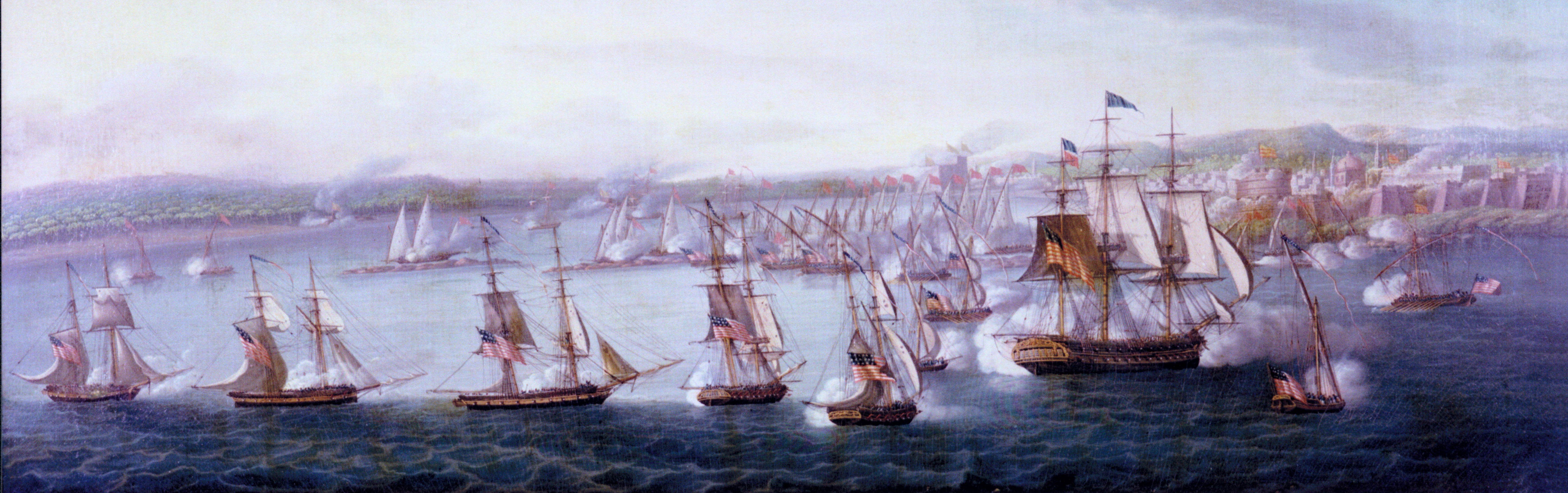
The middle two paintings of ships posted above show those two ships simultaneously flying a "name pennant" from the maintop, a "house flag" from the foremast top, and a "five level code" (likely assigned by Lloyds Insurers.) identifying the vessel in a commonly redundant fashion at that time.
-
 Marcus.K. reacted to Harvey Golden in Flag with ship name reversed on one side?
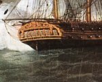
I can't tell if "Otto" is forwards or backwards.
-
 Marcus.K. got a reaction from Bill Morrison in Le Superbe by algeciras1801 - Heller - 1/150 - PLASTIC - Converted to HMS Belleisle
Oh wow, I have to follow this build. The Heller kit of Glorieux found luckily ist way via a not very motivated bit in the big bay.. So I first planned to use it as a test and learn build until I noticed the Beauty of those 74s by a El Supremo years ago. So ist still waiting for the time of real start to build models.. not just visiting others reports.
Love your one !! Looking Forward to see more.
-
Marcus.K. reacted to archjofo in La Créole 1827 by archjofo - Scale 1/48 - French corvette
Hello,
A while back, I captured some general shots of the model. It remains under a dust cover while I´m outfitting the yards. Regrettably, I don't have any recent pictures available right now.
-
Marcus.K. reacted to Jason Builder in Paddle to the Sea by Jason Builder - Solid Wood - 1941
Notes on deviation from original design:
I set out to build an accurate reconstruction of the model from the book, I think I will succeed and fail in various ways.
1. Dimensions and accuracy of shape, form and color: I believe I will be very accurate in these areas. I watched the movie clip above of the ship provided by Navyshooter, and I see three thwarts in the model used in the movie, and I fully respect that model, but I do not see three thwarts anywhere in the book, so I will stick with two. Each interpreter of a model must make their own decisions, and whoever made that model for the movie did an outstanding job in my view.
2. Materials:
a. All wooden parts in the book : pine. All wooden parts in my model: Pine.
b. Lead ballast in the book: Tin/Bismuth in my model....a deviation for safety purposes
c. "tin" rudder in the book, I will use a piece of aluminum, a deviation for long term corrosion purposes.
d. "Enamel" paints in the book, I will use same.
3. Tools: from Chapter 1 in the book , I see a hatchet and two different knives for carving the model. I used a table saw and planer to form the pine blank, and I used a bandsaw to cut out blanks for the various pieces as shown in my photos.....maybe I should have used a hand jigsaw which would have been doable. I did only use knives and chisels for carving, no dremels.
4. Construction: It is not clear from the book how the model was exactly constructed, but the impression I get from the early pages is that the boy carved it out of a single piece of pine. I made my hull from a piece of pine and am making the thwarts, packs, and man, from separate pieces which I am gluing to the model. This may be inaccurate, but! I submit the illustration from the 2nd page of chapter 26 to support my decision to make the man from a separate piece of wood with the grain vertical along the upright plane of the man. For copyright purposes I will not post the illustrations here. The illustration supports that the boy built the model with the man made from a separate piece of wood with vertical grain perpendicular to the grain of the hull. I will use wooden pegs to attach the perpendicular-grained pieces of the man and the canoe.
-
Marcus.K. reacted to Jason Builder in Paddle to the Sea by Jason Builder - Solid Wood - 1941
Goedenavond vrienden,
Tonight was a special night because I got to light a burner, melt metal, and do my best to pour it into my model! At the point I was at in carving the hull and installing the rest of the pieces permanently, I figured I better pour the metal into the ballast slot in the bottom of the hull in case it went haywire and wrecked it.
Micromark Type 280 model casting metal. tin/bismuth alloy with no lead or cadmium (I know a deviation from the lead used by the boy in the book). Melting temp 280degF. I bought two 1 7/8" pucks to melt down but only needed one.
I melted the metal down in a tiny pan, which unfortunately had no spout for pouring. It worked well for melting the metal. I have a heavy pot and ladle for melting lead but did not want to contaminate this "toy" with lead. A simple camp stove was used to melt this low temp model casting metal; it melted quicker than you'd fry bacon. The "camp stove" is not the cleanest in the world as this is the stove I use to melt and make beeswax candles, not for cooking, so there is too much wax residue in the basin of the stove which I need to clean up. Back to model making....I will need to remember this handy alloy for future projects.
But now, to back up a bit, before melting the metal, I levelled the hull in a vise in both directions.
Then, with the metal melted, I walked as quickly as I could, the 20 feet from stove to overturned hull. In that time the hot metal formed a semi-solid skin on it's surface which I had to overcome when pouring, and which caused an overflow over the cavity intended for the pouring of the metal. This is visible in the photo. After this initial spilling of the milk, the pour went perfectly and I will be able to remove the metal from the overflow spill. All told, it would be better to use a deeper melting pot with a spout for this task.
Now I will wait for this to cool and I will file and sand off the metal and all will be well. I had a fire extinguisher at my side during this step.
-
Marcus.K. reacted to Jason Builder in Paddle to the Sea by Jason Builder - Solid Wood - 1941
Hi Everyone!
Got around to some sanding, carving the packs at the bow and stern, and made/installed the thwarts. Continues to be a very fun project.
-
Marcus.K. reacted to kirill4 in Cutty Sark by Bruma - Revell - 1:96 - PLASTIC
Good day,
Dear Bruma,
I have a few pictures of Fl.Cloud model, maybe You will find some idea for configuration / positioning sails on your model... as far as I could see, on this model ,choosed the case when both tacks and sheets of main/ lower courses looks tight at the same time...?!
And position of the yards looks similar to your model yards position...on your model maybe You shown some" excessive "bellies" of lower sails?
Agree ,on the model, it looks "strange" if try to 100% tight and secure fore tack on the cathead...but when compare to Campbell drawings everything should be ok...
hm,strange... are the geometry of the kit model ,such as length of the yards,masts positions, size of the sails mutch the dimensions on the Campbells drawings of KS ?
maybe on the kit model yards shorter than it should be?
Or angle of the yards turn is not sufficient?
At least, maybe there is sence to choose compromise variant when and yards sharp turned but and sails corner positioned in such way when both tacks and sheets looks tight?
-
Marcus.K. reacted to Jason Builder in Paddle to the Sea by Jason Builder - Solid Wood - 1941
Thanks so much for the responses and for sharing your connections to the Paddle to the Sea story!!
Tonight I continued some carving.
I laid out and then carved the recess for the ballast.
I have alot of lead left from past projects wherein I would melt lead and use it in projects. Considering the known health/brain damage risks we now know from lead exposure, I will make a variation from the originally described Paddle to the Sea. I will use low temp model casting metal from Micromark, type 208. I will melt this metal and fill this cavity.
These Flexcut carving chisels are awesome!!!
I am also using my Helle knife:
Hull after rough carving:
Another amazing tool for wordworking, is the SHINTO RASP" pictured below. Amazing, efficient, tool with two different aggressiveness faces.
-
Marcus.K. reacted to NavyShooter in Paddle to the Sea by Jason Builder - Solid Wood - 1941
The movie:
-
Marcus.K. reacted to Roger Pellett in Paddle to the Sea by Jason Builder - Solid Wood - 1941
What a great project!
I too grew up reading Paddle to the Sea. I loved the book. 35 years ago I was fortunate to be given the opportunity to move from the Ohio Valley to accept a new job in the Great Lakes region and I accepted it in a heartbeat. I can just barely see a tiny sliver of Lake Superior from a window on the second story of my house. I also made sure that my children grew up with the book too.
Did you know that there is a Paddle to the Sea movie too? Here in Duluth the Army Corps of Engineers runs a nice museum dealing with Lake Superior. During the summer tourist season they show movies about the lakes in a conference room. Visiting with my two kids and my granddaughters the announcement came over the speaker that there had been a special request from a family visiting to show Paddle to the Sea. My daughter had made the request. The movie while beautifully filmed cannot reproduce the 1940's picture of the industrial lakes that Holling does with his book.
Roger
-
Marcus.K. reacted to Jason Builder in Paddle to the Sea by Jason Builder - Solid Wood - 1941
The pictures of the model clearly show a shallow recess in the interior of the canoe. Here I am carving that recess.
And here is the current rough carved status:
-
Marcus.K. reacted to Jason Builder in Paddle to the Sea by Jason Builder - Solid Wood - 1941
Hi!
Starting on the paddler himself. Also of pine.
With the blank cut out on the bandsaw, I started rough carving the figure.
-
Marcus.K. reacted to Jason Builder in Paddle to the Sea by Jason Builder - Solid Wood - 1941
Hi Everyone,
The book states the model was made from a piece of pine, so here is my raw material, scrap 2x4 from the shop:
The 2x4 is not quite thick enough, so I sawed and planed two blocks which I will glue together to make the hull blank.
Here is the hull blank glued together , and cut and planed to finished length, width , height. I made some paper templates of the plan view and profile shapes of the hull. Tracing the profile here.
Profile cut using the bandsaw:
Tracing on the plan view shape:
Here is the blank cut out on the bandsaw.....all carving from here on out:
-
Marcus.K. reacted to Jason Builder in Paddle to the Sea by Jason Builder - Solid Wood - 1941
Greetings!
And now I return to the dreams of adventure of my youth! "Paddle to the Sea" is a childrens' book, written and illustrated by Holling Clancy Holling, and published in 1941. It tells the tale of the voyage of a small carved wooden canoe and it's paddler as they follow the currents of the Great Lakes, from Nipigon country out to the Atlantic Ocean. A Native American boy carves the canoe and it's stoic captain, paints it, and places it in the snow, high in the hills over Lake Nipigon. When the snow melts, it takes "Paddle to the Sea" with it, and the book tells the story of all the people, machines, technology, animals and natural wonders that the little canoe models seas on it's epic journey through the Great Lakes to the Atlantic. I loved the book as a boy, and I still have the book. I live in Wisconsin, not far from Lake Michigan, and the book has always been special to me. As a boy I thought how cool it would be to make this canoe and paddler model......now I have decided to do it! Below is documented my best attempt at building as close to accurate a model as possible of the actual "Paddle to the Sea" canoe model from the book.
Making the drawings: There are illustrations throughout the book of Paddle to the Sea, and there are also good clues as to materials, dimensions, and finish. The book tells of the young Native American boy in Nipigon Country (North shore of Lake Superior, around Lake Nipigon), who take "many days" whittling a "piece of pine" into a "canoe one foot long". It also advises of a rudder made of tin and lead ballast. The book also advises "oil paints" were used to paint it, along the with words carved into the bottom of the hull , "Please put me back in water, I am Paddle to the Sea". Starting with the known length of 12", I scaled other dimensions from the many pictures in the book and calculated the various dimensions. Then I took those dimensions and created a life-size, to-scale, color drawing of the model, which I will use to take dimensions from as I build the model.
-
Marcus.K. reacted to CiscoH in Armed Virginia Sloop by CiscoH - Model Shipways - 1:48
A much quicker than usual update! Mostly because I was off work yesterday and now I have a question-
Progress so far- I want to make my decking and waterway out of Holly, so first step was cutting my Holly billet into strips. Woodworking is my other hobby so I already have a bandsaw.
I set the fence so it was a little wider than than laser cut walnut that came with the kit. Except after cutting 3 strips of Holly I realized I had the wrong strip of walnut; I picked out the piece with the cap rails which is thinner (1/16") than the waterways strip (1/8"). In my defense they looked very similar. Also its freezing in the garage (16 degree F) and I was hurrying. Below is the billet, then the correctly cut 1/8" (+ a little more) holly strips next to the correct walnut strip, and on the right the 4 strips of holly cut too thin. They will find use I'm sure somewhere else.
You can see there's a knot in the middle of the holly billet but I think dividing up the waterway into 2 pieces each I can cut out what I need. To final surface the holly strips and bring them to 1/8" thickness I reused my blockplane jig. It was made to surface the stem and keel which were 3/16" thick, but luckily the kit comes with lots of strips of basswood of all different sizes. So i used some to shim the holly strips up, blockplaned 1 side a few passes, then turned the strip over and did the other side. Then just keep flipping and taking a shaving until final thickness reached. It went a lot easier than I had planned.
So finally I reach my question. The practicum illustration of the gunport planking, pictured in my last post, clearly shows the bulkhead extensions to be 3/64" thick. The practicum also says to sand down the knighthead and timberhead extensions to 3/64". He makes no (written) mention that I could find of the other bulkhead extensions, and his picture in the practicum shows them clearly unthinned and much thicker than 3/64" after his waterway is installed. I reviewed some of the MSW AVS logs and it seemed like no one had thinned any other bulkhead extensions except the bow ones.
And I think I remember Chuck saying somewhere that having fat gunports was a common mistake.
So I took the front 3 bulkhead extensions to 3/64", that seemed uncontroversial at least.
The grain dives outwards on the kit bulkhead extensions so I promptly split the 3rd one starboard side and had to reglue it. So now I am deciding on thin all the bulkhead extensions to 3/64", which is pretty skinny, or thin them to a regular but "thicker" thickness which is what the practicum photo, but not the practicum illustration, shows.
Any advice would be appreciated.
Thanks for reading, and all you in the Mideastern USA hope you had a great snowstorm. Yesterday off from work was great but my kids were off school as well (less great) and they're off today as well and they really need to go back.
Cisco
-
Marcus.K. reacted to CiscoH in Armed Virginia Sloop by CiscoH - Model Shipways - 1:48
Good evening ModelShipworlders. Thank you to all who have read and liked my posts, I appreciate it. My last 2 weeks have been spent trying to up my planking game, and if mistakes are a sign of progress the I've had some success. Following Bob Hunt's practicum (I thought) I attached the first line of planking just at the deckline to stabilize the bulkhead extensions from breaking. This involves attaching an 1/4" wide by 3/64" deep plank overlapping each side of the subdeck, and a single 1/8" x 3/64" plank above it on each side. I attached the 1/4" wide plank in my last post, go me, and then found some issues.
First off the whole "bend downwards to make the plank fit on the curve of the prow" makes a lot more sense to me. Now. You can see in my fist pic that there is a gap that I filled with some scrap basswood between the plank and the first bulkheads which I originally thought was because I hadn't faired the bulkheads enough. But in hindsight I realize I probably didn't bend the plank upwards enough as well.
And then I found my second mistake. Reading other logs I have scoffed at people who have used the wrong sized wood strips, how hard can it be to mess that up? Well when I was adding my second strip it seemed a bit thinner than my first strip, so I measured it and somehow I managed to pick out strips 4/64" (1/16") thick instead of 3/64". So maybe that was part of why they were so challenging to bend.
So not a lot of harm done and maybe practicing on a harder strip of wood will make the others easier. I added the next strip of planking, 1/8" x 3/64", this time the correct size, but I somehow thought the directions said to add a strip both above and below the original plank, instead of just a single strip above the original plank. So I added a strip below the original plank, and this one I bent with a better curve downwards at the bow and upwards at the stern so it followed both the original plank and the downward curve of the bow bulkheads pretty well.
I did both lower planks, then started attaching the 1/8" x 3/64" strip above the original plank. I was getting more confident at this point and glued most of the strip on in one go. There is a slight gap which you can't see in the pictures between planks at the upwards bend at the level of the quarterdeck. I think my bending jig compressed the wood here a little making a divot that only showed up now. But this is why a first planking is helpful - I am learning a lot about what to look out for on the show second planking.
It was at this point that I re-read this section in Bob Hunt's practicum and figured out I had mistakenly added the 1/8" lower plank. I think the practicum really proves it worth in the following picture which illustrates all the planking and thicknesses at the deckline. Even if it kept leading to "aw man..." moments. Admins if I can't post this please remove it-
And here finally I am gluing the other side. I also learned its time to buy some bigger clamps as clothes pins won't open any wider.
And thats it for tonight. Next up is thinning the bulkhead extensions and adding the waterway. I'm doing mine in Holly and I'm planning on having one or two scarfed joints instead of single big curved pieces that run from the quarterdeck to the bow. Loosely based on Cheerful's waterways. This time I will try and read the directions, too. Thanks for reading, Cisco.
-
Marcus.K. reacted to CiscoH in Armed Virginia Sloop by CiscoH - Model Shipways - 1:48
So on to attaching the first plank. Like basically everyone I found out my fairing of the bulkheads wasn't as great as I thought. Not shown in these pics but I had to slip a tiny piece of wood into a gap between the first bulkhead and the plank. You can see my clamping method which worked pretty well, especially as I had spent so much time trying to bend the strip to be very close to my penciled lines on the bulkheads. Due to Timidity I attached 5 bulkheads at a time, allowed them to dry, and then evaluated my technique. I also found out that if you are using heat to make the plank bendy you can dry it out so much that even a little bend can break it (See below pic on about 6th bulkead). But the break glued back fine.
I used a piece of my second planking (Holly) as a wedge in rabbit joint at the top of the stem to make sure there will be enough space down the road.
The aft end of the plank is very exciting- it curves upwards and inwards, and the final 1 cm also twists to follow the transom edges. Before gluing the last few inches I wetted the strip and twisted the end while using the travel iron. Couldn't take a picture I don't have enough hands but it worked really well.
I also wetted the outside of the plank as I attached it in the hopes it would swell a little and curve inwards, and not break like it did amidships.
And thats the state of the union. Have a great night, thanks for reading, Cisco
-
Marcus.K. reacted to CiscoH in Armed Virginia Sloop by CiscoH - Model Shipways - 1:48
I am way overdue an update, although it doesn't look like I did much. First off I had to fair the bulkheads and it seemed like every other one needed shimming. I kept laying a batten longwise and comparing, trying for a smooth rounded "bulge" as opposed to the accordian-like ripple I started with.
I had to finally stop fairing before I sanded away the entire model. Next up was the framing for the stern transom. Oddly enough in the practicum Mr Hunt did taper the 2 innermost stern frames; luckily this was noticed and addressed by enough MSW buildlogs that I remembered.
I made a spacer the size of the window frames and used it to keep the stern frames the same distance apart.
After adding the stern frames I the upper wing transoms and the lower filler blocks, along with whatever the blocks of wood on the sides of the transom are called.
Then I carved and sanded the transom/counter area so it was round from the side view, and flushed the side transom blocks trying to keep a nice sweep by laying my batten along the sides.
Finally I added the window header and sills. Something about the parallelogram windows placed on an upward curve has always looked off to me. The windows supplied by the kit are slightly different; the inside ones seem to have more of a tilt than the outside ones. I am going to try and scratch my windows as the kit ones look chunky to me, and I'm sure there will be some adjustment in placement, but that is Future Cisco's problem.
And thats it for tonight!
May your holidays be full of comforting family drama and no real drama. Cisco
-
Marcus.K. reacted to CiscoH in Armed Virginia Sloop by CiscoH - Model Shipways - 1:48
One thing I didn't anticipate is how long, or more importantly how much energy, it takes to type and upload pics. Competes for my "reading of other people's updates" time. Here's this week's slow progress; first off I shamelessly copied someone else's great idea, and I'm sorry I can't remember who it was, of making curved sanding sticks for leveling the dorsal bulkheads. I glued some thin strips of walnut i had laying about not being productive, then attached 150 grit sandpaper with double sided tape.
I found out that you tend to use just the last 2 inches of sandpaper so it has to be changed pretty often, but worked well. I made another thinner and more curved sanding stick to get closer to the bulkhead extensions.
I then was faced with a quandary- how do you make sure the tops of the bulkheads are level? I don't have an exterior frame built yet to hold the ship at 90 degrees to a base so what to use as a reference surface? So I tried drawing lines 90 degrees to the keel with my square; it was awkward but worked. Kinda.
Then I glued in the beam supports for the tiny quarterdeck referencing it level from lines I'd drawn above it.
Then i added the quarterdeck, which seems big enough for maybe 1 person at a time. Once that was dry I leveled the main deck with aforementioned curved sanding sticks. I quickly gave up trying to make sure everything was 90 degrees to the keel; it was just too hard to compare both sides of each bulkhead. So instead I used the short end of my LeeValley square, measuring across 4 bulwarks at time to level them, adding strips of wood where things were low and sanding high spots. You don't initially appreciate how much more challenging having the deck shaped like a banana with each end up, in addition to the bulwark's downward camber towards the rails, makes this whole process. Well now I sure appreciate it.
But finally I got it as level as it was easly gonna get and glued on the maindeck. Which is presently drying. Next up is sanding the bulkhead edges for planking. Per the practicum this should take 15 minutes a side. I am skeptical its gonna be that easy. Thanks for reading, off to enjoy a deserved adult beverage. Cisco
-
Marcus.K. reacted to CiscoH in Armed Virginia Sloop by CiscoH - Model Shipways - 1:48
3rd update! I managed to add my SuperCool avatar picture and downloaded Adobe Photo Express (its free and so far intuitive) to edit my photos. Searching MSW the sideways pictures problem shows up a lot and is possibly due to large file sizes so I decreased the bytes or pixels or whatever and heres hoping they stay upright. If you didn't guess I don't like computers and they don't like me. But a necessary evil.
I finished gluing in the bulkheads with yellow glue which seems to get everywhere but is very solid. Per the Hunt Practicum next step is to add the very thin aft/poop subdeck. First I leveled the top of the bulkheads by filing them flat; one I had to glue a strip from the subdeck "sprue" as it was too low.
Next I had to attach the subdeck to the curved surface of the bulkheads. The practicum has you push tiny pins through the top of the subdeck into the bulkheads, then pull them out once the glue dries. I tried a different approach- overbend the subdeck and hold it in place with rubber bands. So first step is bending the subdeck. When I built the Model Shipways LongBoat I spent so much time bending the planks by soaking them in warm water for a while, then rubber banding them to cans or glasses to impart a curve, and leaving them overnight to dry. They would usually end up curved like I wanted but took forever to dry, and whenever I clamped them no matter how dry they seemed they were always still a bit wet and would dent. Then they eventually dried out and shrank and left a gap.
So I decided to try the Chuck technique of minimal water used mainly as a heat transfer device and let heat melt the lignins. The thin subdeck is very flexible so bending it is easy. After spritzing both sides with a small amount of water spread evenly with my finger I used some string to tie the subdeck bent around a coffee cup.
Then I attached my blowdrier to the workbench (actually my woodworking sharpening station) with spring clamps, turned it on Low Heat and dried the water off. After the top part was dry I took off the strings and the back was still wet so I dried it by just holding in bent in my hand. As long as the heat isn't directly hitting your fingers its not bad and took about 10-20 seconds each side. And presto, dried with a nice curve. And I didn't have to leave it overnight. While this was a very thin piece of wood compared to some of the planking strips I hope this is a prelude on how much easier this method is.
Now that the subdeck was bent (overbent on purpose) I did a test run with rubber bands and that seemed to hold it in place pretty well so I forgoed using the tiny nails. Once fitted in place there were some tiny lift-ups that I added pencils to direct downward force and it all seemed to work pretty well.
And finally here are 3 pics of my finished MS LongBoat. Lighting in the basement is from the ceiling so it shadows the lower parts of the hull, another thing to work on. I felt that many model ship bases were too short, running from the stern to the prow, with the bowsprit sticking out waiting to be caught on something, so I made my base extra big. Maybe too big in hindsight it may overwhelm the model some.
Thanks for reading. Have a great night, Cisco