


luc
-
Posts
24 -
Joined
-
Last visited
Content Type
Profiles
Forums
Gallery
Events
Posts posted by luc
-
-
On 2/15/2021 at 4:02 AM, Mau said:
Guys, do you know why there is a frame number (3)? Is It the same frame 3? What are the numbers of the frames next to zero?
On 2/15/2021 at 4:16 AM, druxey said:Any frame letter or number with brackets around it signifies that it is exactly the same as the dead flat.
Druxey : dead flat = the biggest frame, google give not a good translate.
I find it a good question of Mau
wich numbers next to 0.
where must come frame 1 and 2, wich side of the zero.
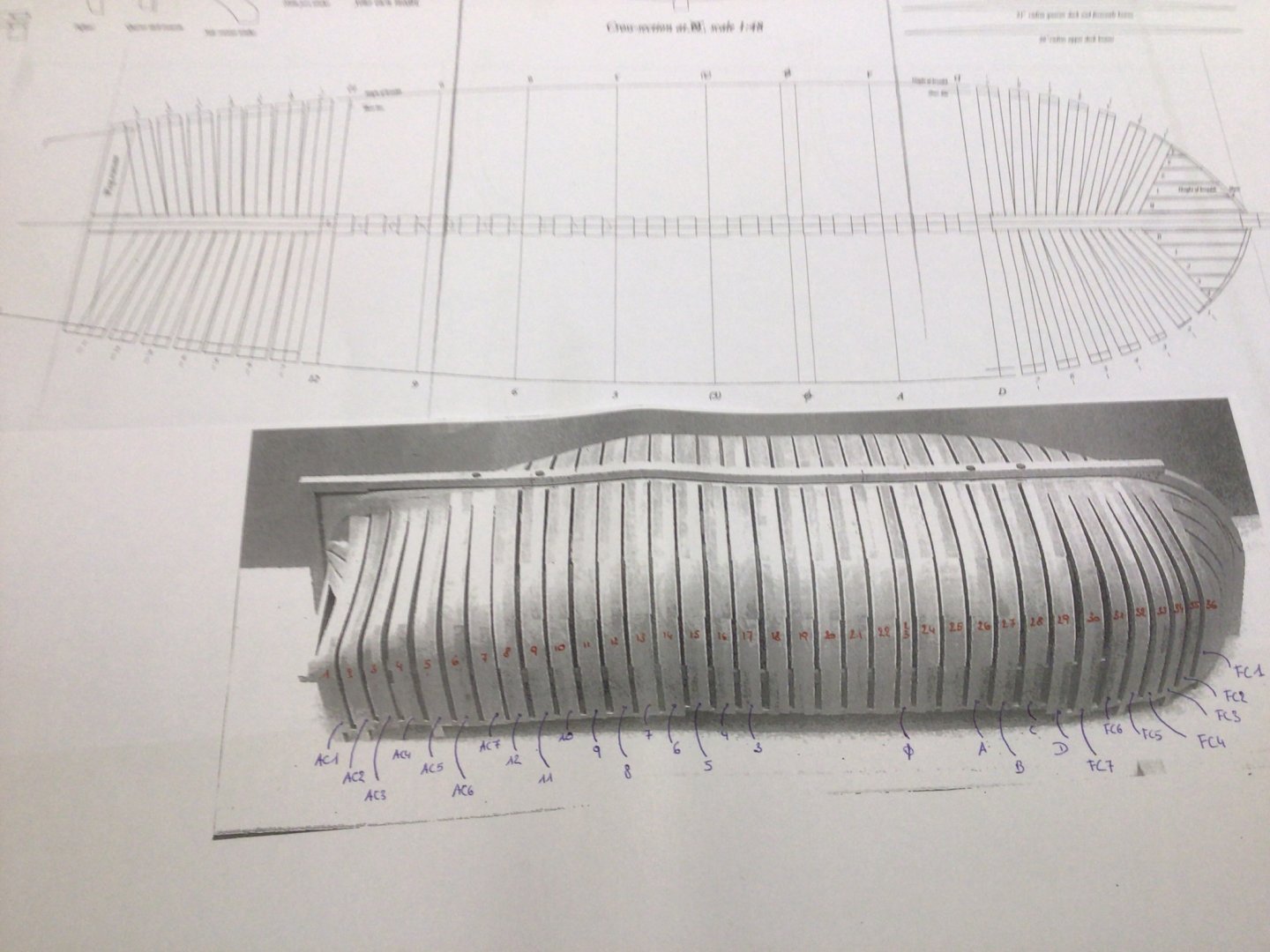
I numberd the frames, but what with frame 18 to 25.
???
- GrandpaPhil and mtaylor
-
 2
2
-
-
1 hour ago, JpR62 said:
Be careful to use the good system !
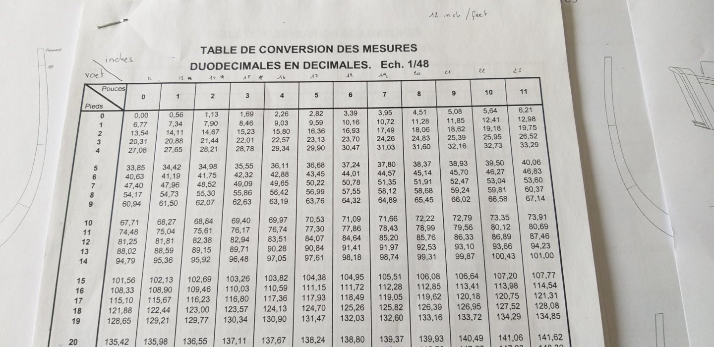
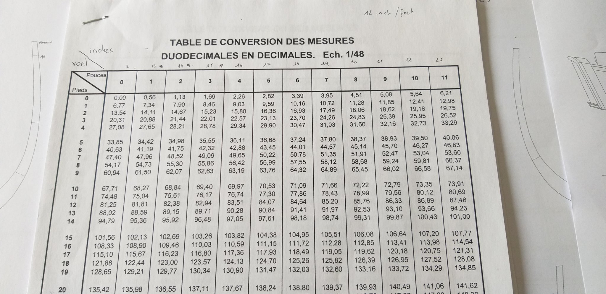
The old French (Ancien Régime) inch equal 2,707 cm
The British inch is equal to 2,54 cm
The Ancre monograph refers to the old French inch
The table of conversion that you reproduced in your message seems to refer to the French system : 1 French inch (27,07 mm) divided by 48 gives 0,56
but the British inch (25,4 mm) divided by 48 gives 0,529 mm
As indicated by druxey, the ship was built using British feet and inches.
You need to find a conversion table for the English system.
Thank you, now I know why my calculations would not add up, was already starting to doubt my own brains. -
15 hours ago, druxey said:
The measurement question is answered in that the ship was built using British feet and inches, ans measurement for the model are quoted in the same system.
Instead of driving yourself crazy converting measurements from duodecimal to metric and then dividing by 48, try to buy a scale ruler (on eBay or elsewhere) that has a 1:48 scale on it. Then you can measure everything directly.
Firstly, I would like to thank you "Druxey" for forwarding me the missing Frame.(one problem less)
thank you very much !!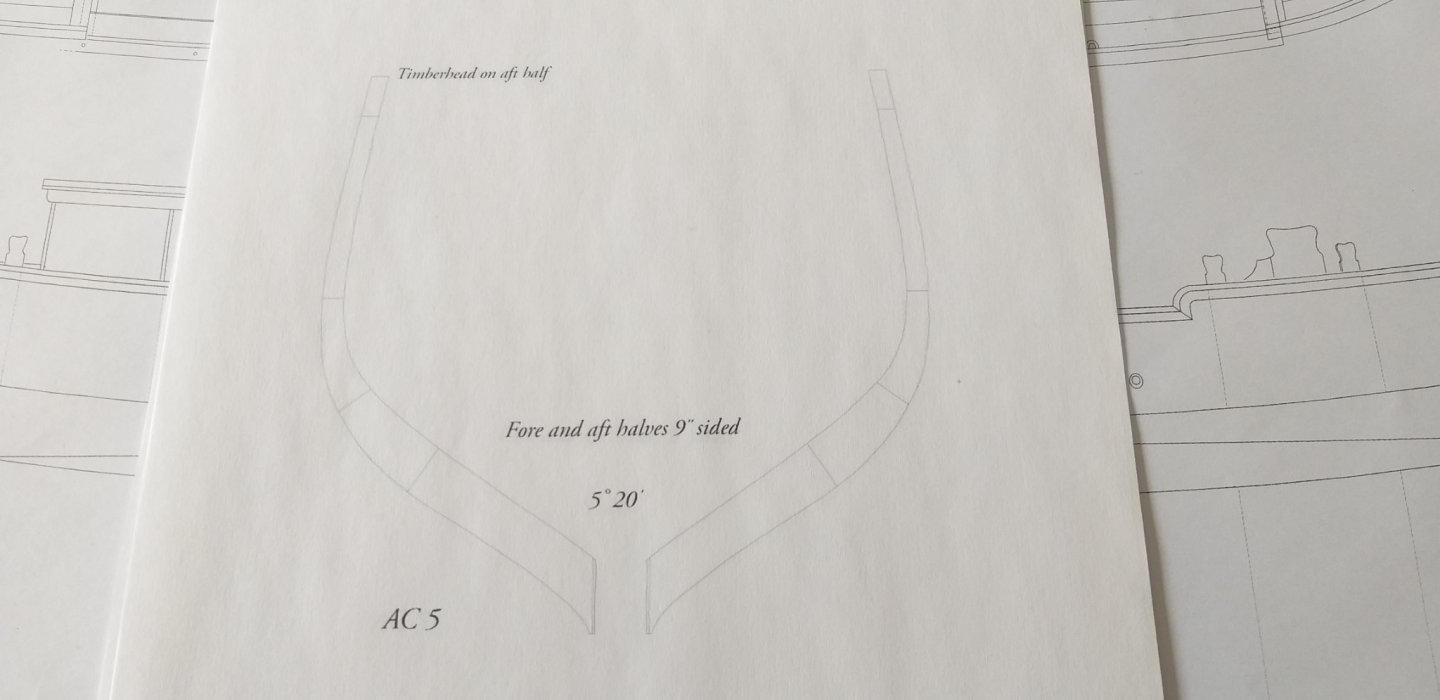
Second I want to thank you, with the quote "converting measurements from duodecimal to metric and then dividing by 48"
Last year I took classes in Belgium to understand Ancre's monographs.
The teacher gave these documents as an extra, never thought I would use them, but they are now very useful.
Thank you very much again !
- GrandpaPhil and mtaylor
-
2
-
Quote
Making progress, albeit rather slowly. As they say, “The hurrier I go, the behinder I get.”
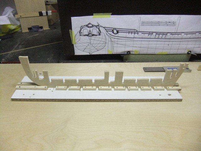
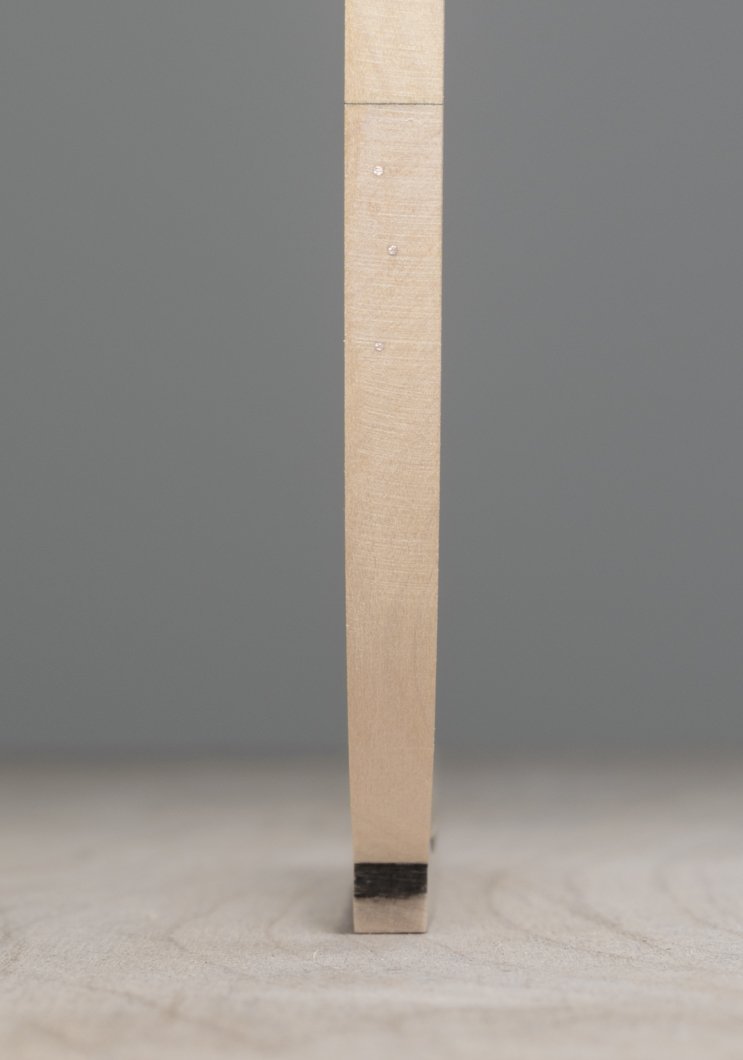
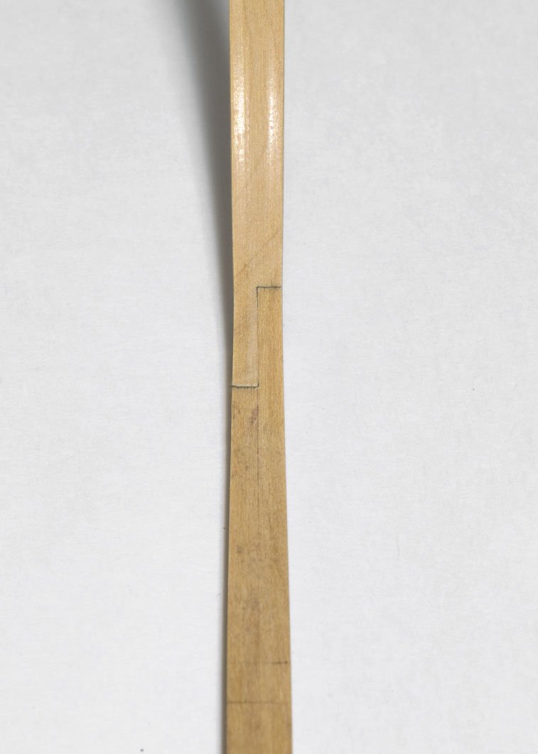
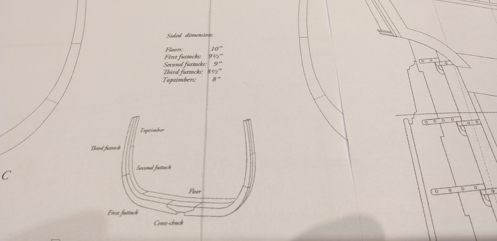
The tapering of the keel and stem should be done before the rabbet is cut. The fore end of the keel is tapered from 12" to 10". This also reduces the width of the lower stem at the boxing joint. From there the stem is given a gentle taper to full width just below the whales. The transition from the boxing joint to the stem can be tricky, so care was taken while sanding.

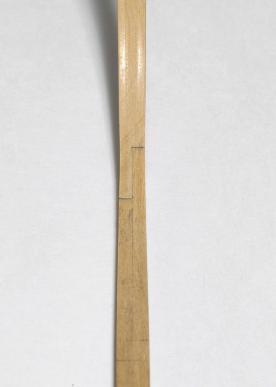
The aft end of the keel is also tapered down from 12" to 10". Once all the tapering is completed, the rabbet can be cut. The rabbet has been turned vertical and is approx 2 1/2" deep. This will allow for some adjustment later when the 3" planking is added.

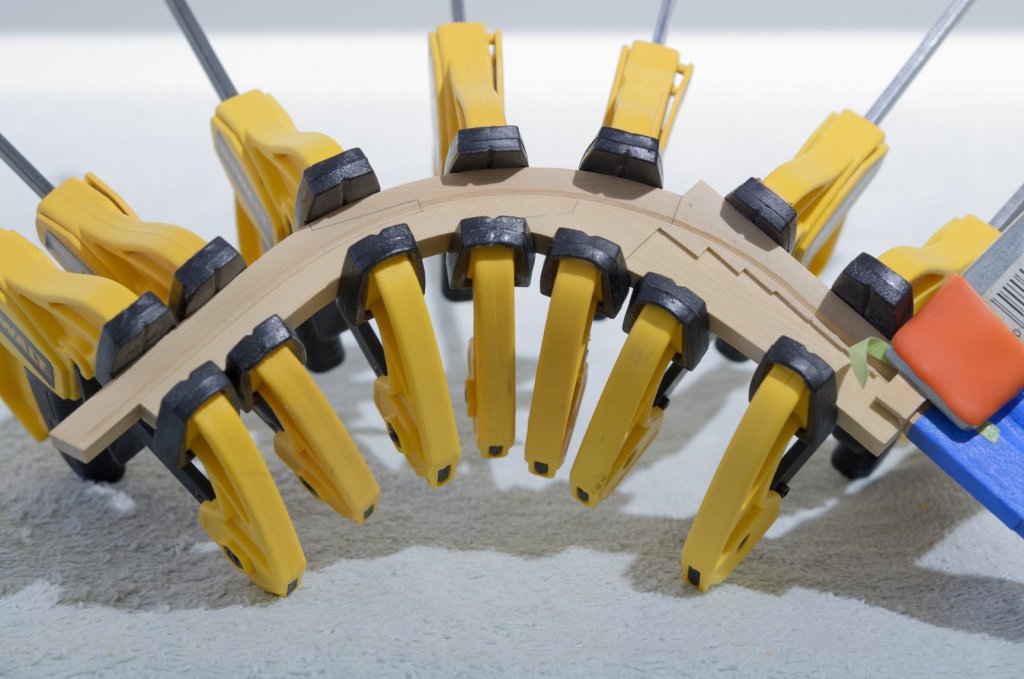
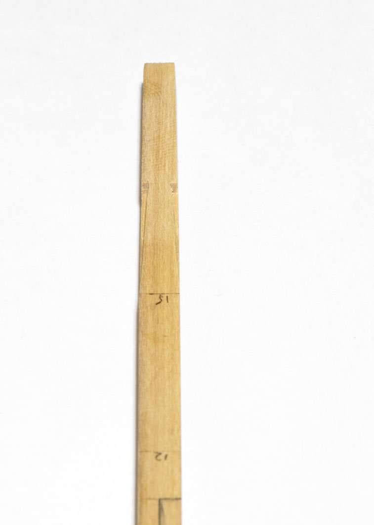
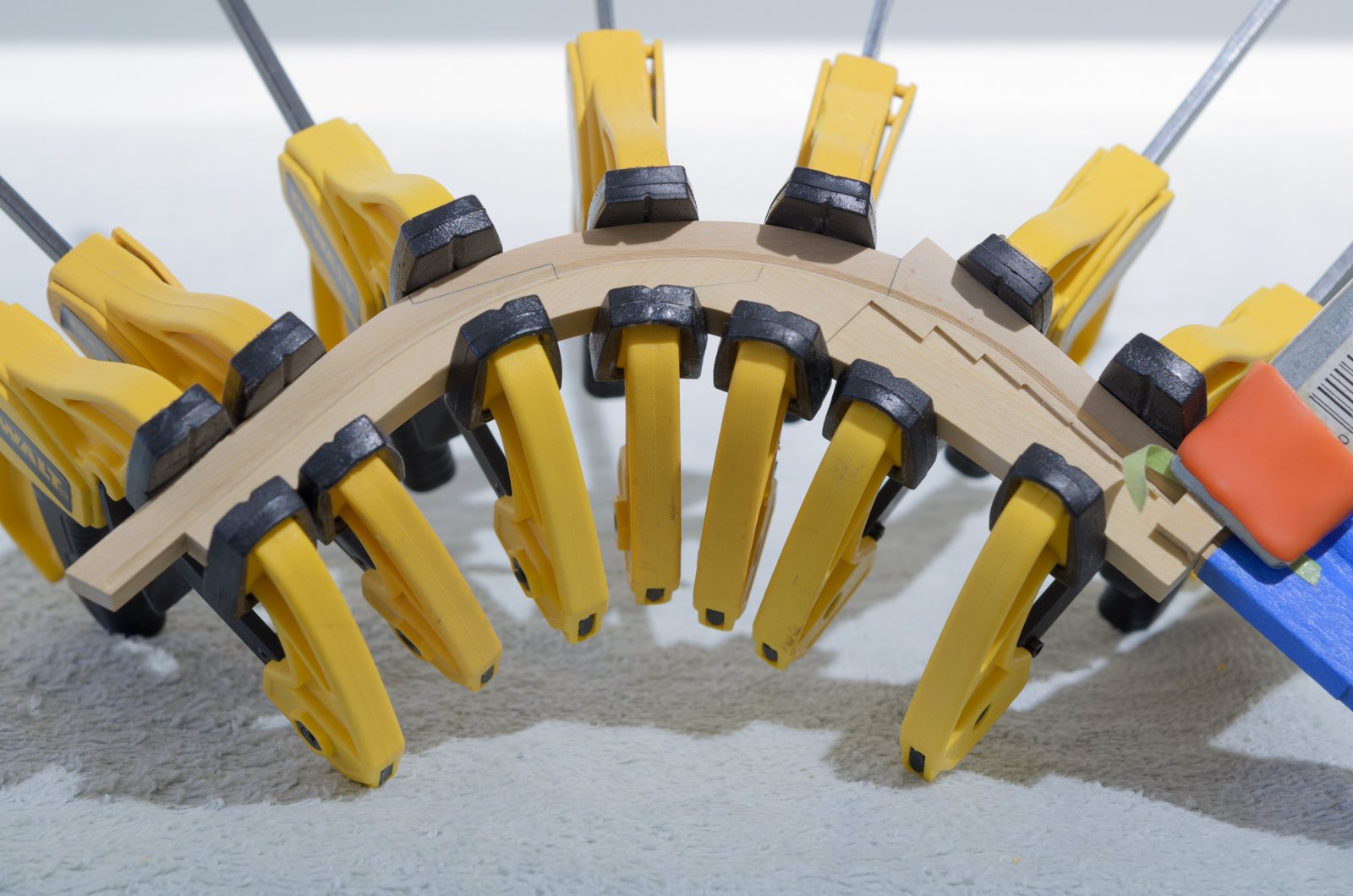
The fore deadwood and stemson where made from 15" boxwood sheet. The stepping line was done on the mill. There was no visible light coming through the joint prior to gluing. Those clamps come in handy!
Mike
Edited August 26, 2017 by StuntflyerI copied this from Mike (Stuntflyer) topic The Hayling Hoy
He tapered the aft end from 12" to 10".
the rabbit is 2 1/2" deep
I think that " means something else.
-
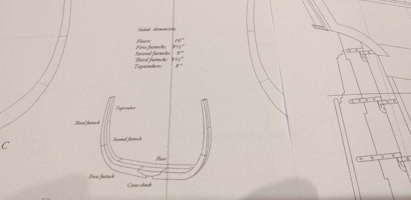
I have a little question?
As a European, I am used to working with the metric system.
These plans are drawn in the English / American system and use inches, feet, etc.
On the plans for the width of the frames I see dimensions in inches (I suspect)

I am supposed to do these values each time multiply by  2.54cm and then convert them to a scale of 1/48

Or am I wrong?
Why am I asking this, my calculations don't match what I'm measuring on the planExample:
- GrandpaPhil and mtaylor
-
2
-
-
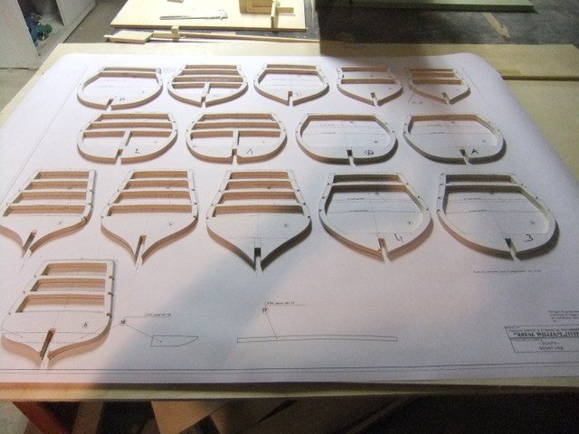
My new project, do not expect long texts because I don't like to write
and my englisch is bad,
but through this way I still want to let other woodbuilders enjoy my work,
just as I enjoy their work on this forum.
Why this ship
This ship would be ideal as a beginnersboat to make a full frame without having
to make 100 gunports and 3 identical decks.
Everything that is present in a large ship is also reflected in this boat. (Except armament)
A good exercise if we plan to build a larger ship.
Furthermore, this has the advantage that this is a project of 2 years, while a large ship is quickly a multiple of this time.
Let's start.
After waiting for 2 months, a package finally arrived in the letterbox from
America this week.
After opening the package this came out:
![20210213_130211[1].jpg](https://modelshipworld.com/uploads/monthly_2021_02/1029348103_20210213_1302111.thumb.jpg.bdee9969aadc6ffeacd0013f3be7da3d.jpg)
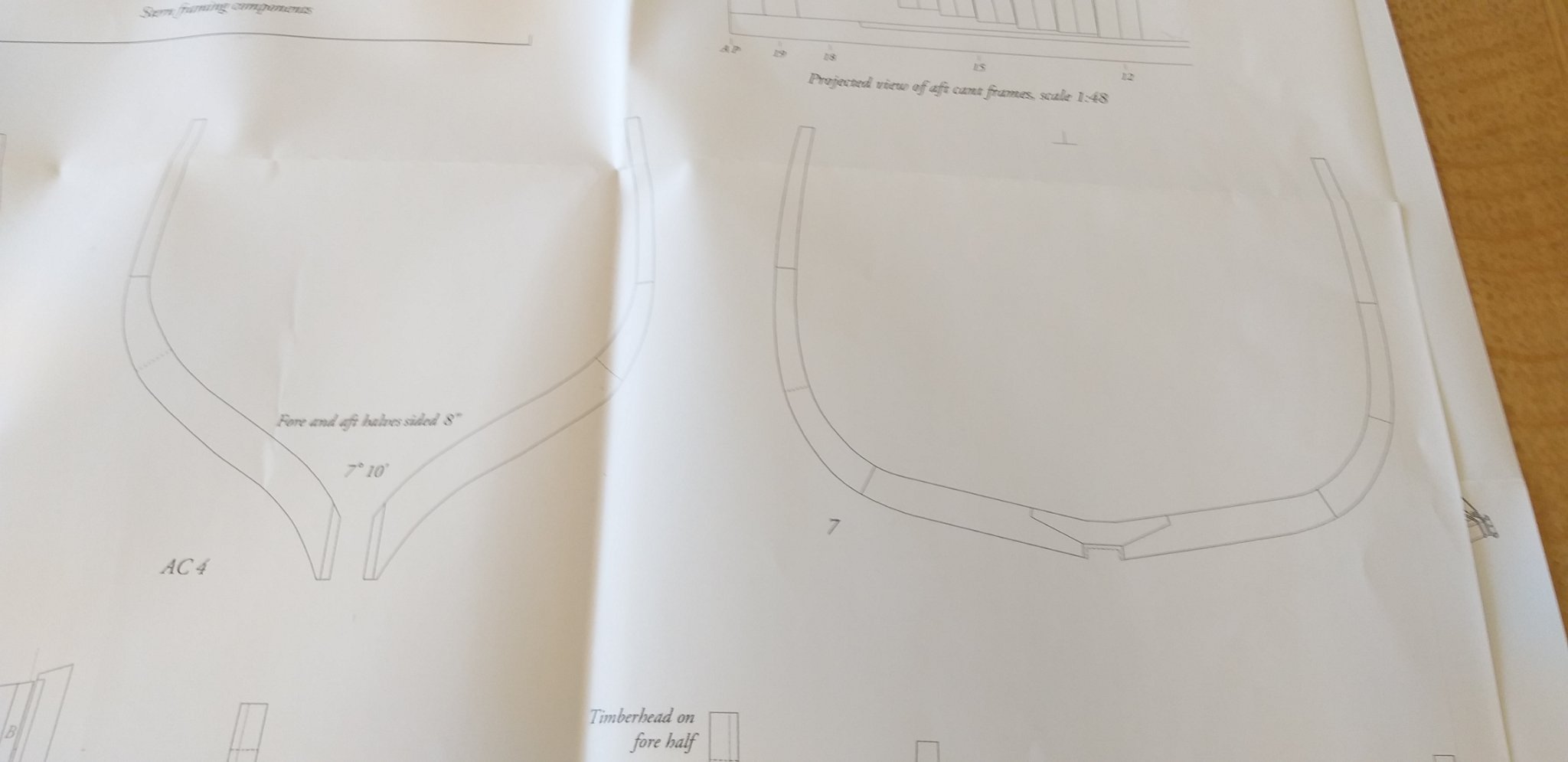
A complete building description in book form
3 plans by The Hayling Hoy
Advertisement
And a correction because a frame would have been omitted from the plans.
The book looks decent with beautiful color photos,
but saddly (from belgium) the plans are not drawn up in the metric system but in inches, feets etc.

A bigger disappointment, the paper with the missing frame.
A mistake has happened here somewhere because the supposedly omitted frame
is on the plans.
What I do miss is frame AC5
In place of AC5 is frame 7, and instead of sending me AC5, they send me frame fc7 again.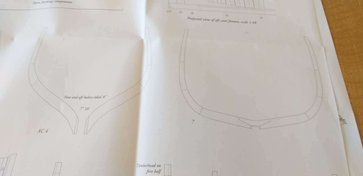
I don't know yet how to solve this? Does anyone has this frame? Now the study of this ship is starting, do not know yet whether I will make it in steamed or plain pear wood. Time will tell. -
On 11/12/2017 at 10:34 AM, archjofo said:
The last details on the masts are made.
These are hoops around the lower masts with holders for pins,
so-called spider bands.
The holder was made of brass investment casting.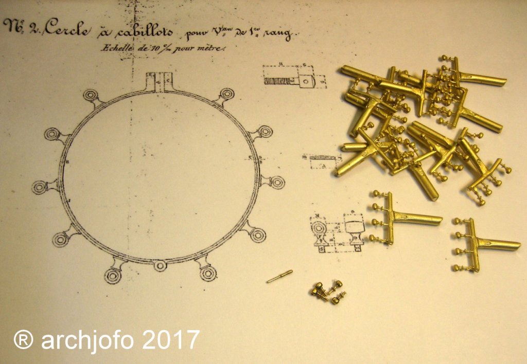
and a last question : brass casting, how do you do that?? I never seen this before. Do you have a tutorial ???
-
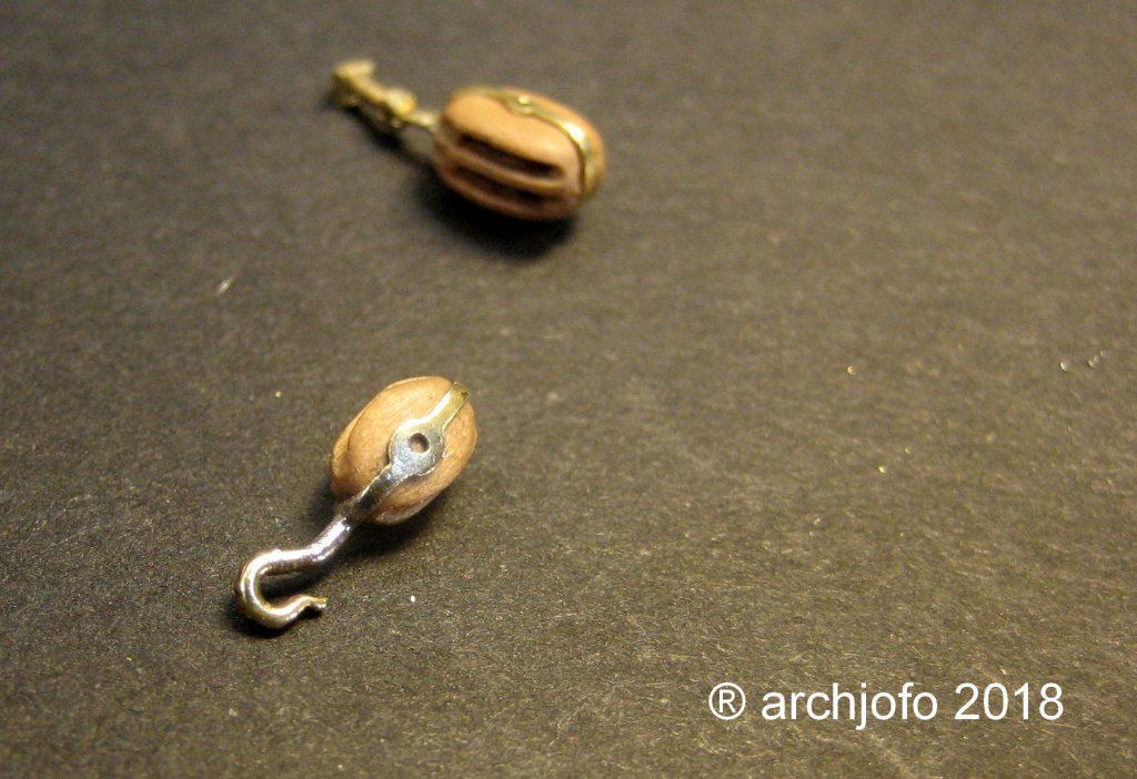
On 4/16/2018 at 7:59 PM, archjofo said:
Hello friends of model making,
thanks for the interest, especially thanks to Carl for
the last nice comment.
At the moment my job takes me a lot.
Therefore, there is little time for the hobby.
In that respect, I can only show a little.
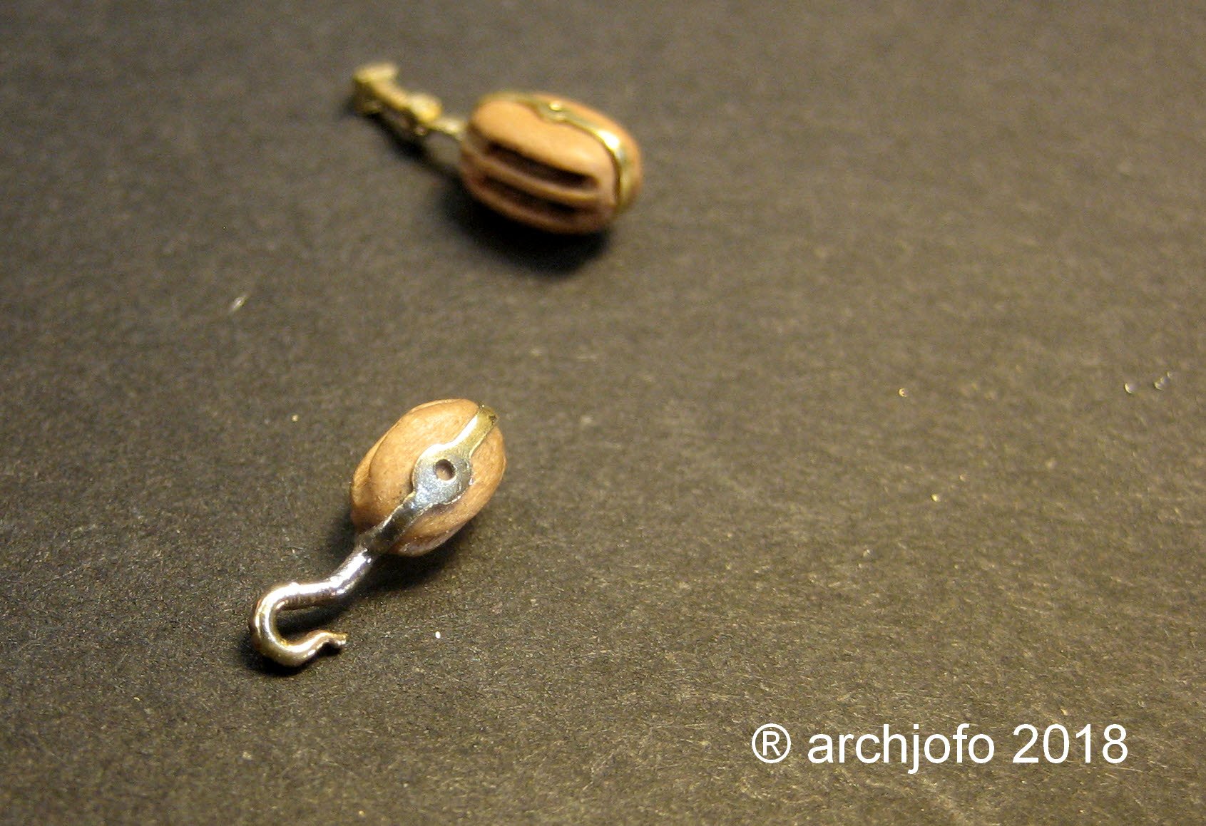
The iron fittings of the blocks for the backstays
Other fittings are for the double blocks for the boat davits.
These blocks are equipped with hooks.
For this my first attempt. This is not optimal yet.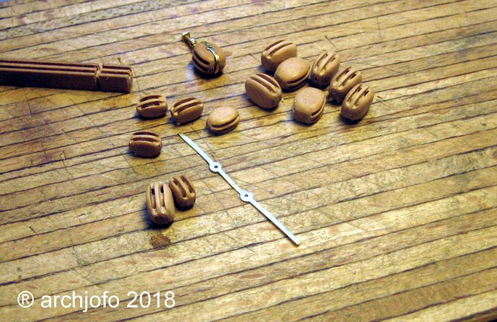
Johann,
another question : where did you commissioned the etched parts. (I am from Belgium)
regards Luc
-
-
Very nice indeed, are you still using walnut wood for nailing, and what's the thickness?
-
-
thank you Greg
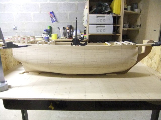
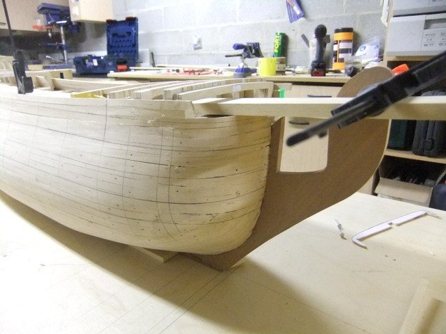
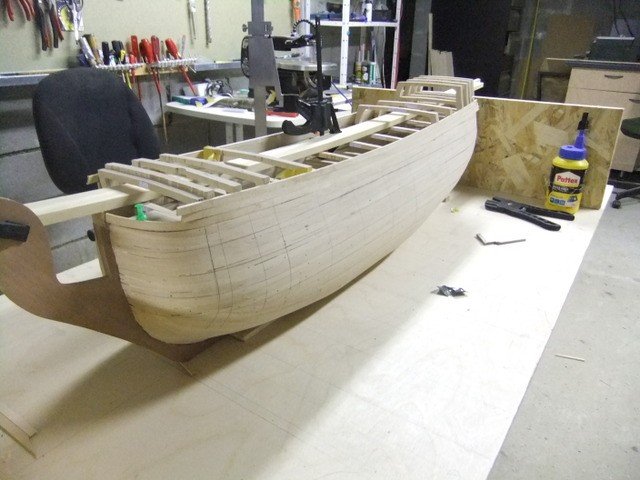
the progress of the last month.
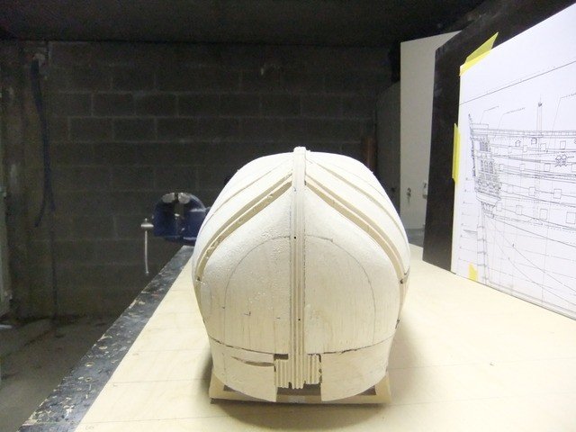
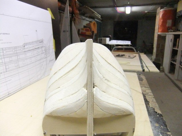
finishing the first planking and putting the lines on the hull so i can check of everything is still ok.
On my stern there is a different of a few millmeters. In the kit the frames are 6mm thick , i used +/- 9mm.
this give a mistake of 1.5mm, not much , but to much for the basic to build on.
- Keith_W, Farbror Fartyg, Omega1234 and 1 other
-
4
-

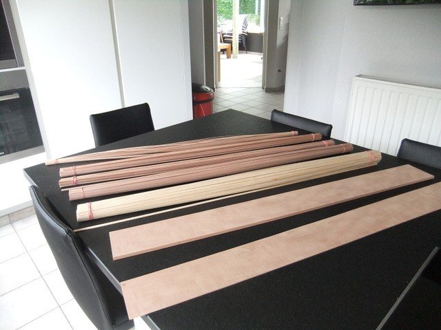
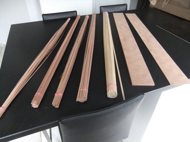
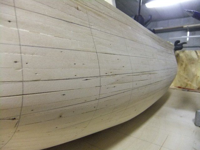
Friday the wood arrived so i can begin the first planking.
Swiss pear from Arkowood.
- Omega1234, Landlubber Mike, mtaylor and 1 other
-
4
-
-
KeithW :
The Santisima trinidad was painted with humbrol paint.
Now I want to really just plain wood.
Vic built his ship also with pear, therefore this choice.
What would you use ??
ps: the pear would by painted with G4 , a colorless varnish.
Pete:
Found you resourcefile a time ago. Becaus i build this ship Rc, my approce of the building is differnt.
My next step is the first planking and the rudder and to make everything rechabel and functionel. Once this is don, I need your resourcefile much more.
-
Thank you Simon, found it.
I know i had seen it somewhere a time ago, didn't found it again.
thx Luc
-
Because i want to build this boat in swiss pear (from arkowood) .
It's now time to find out how much wood i need and wich dimensions.
I'm searching for a list of the wood that in the box of euromodel, but i can't find nothing.
Is there a link of these list ???
thx Luc
-
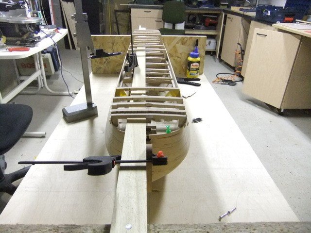
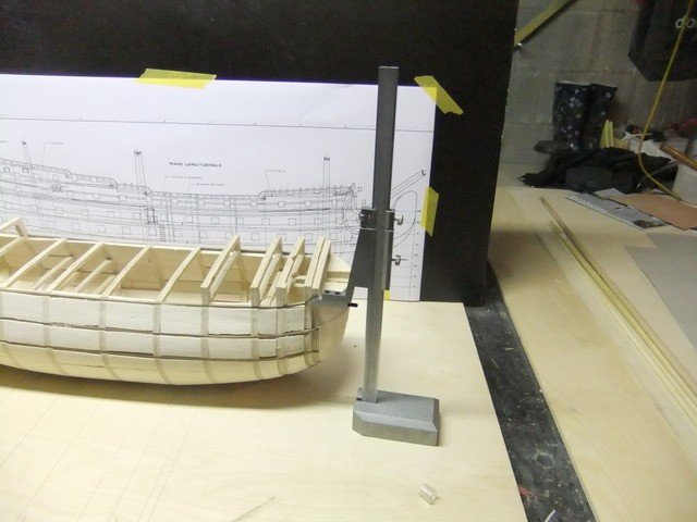
A few photos of the work I did the past week('s).
Because my english is not very good, even bad, i post pictures instead of text.
the end result
bow
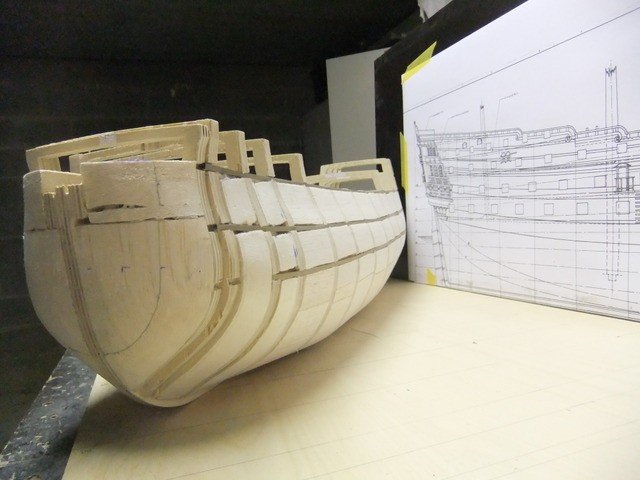
stern
Top (u see the holes for the frontmast and bowsprit) Everthing must be maked strong for sailing and transport the ship)
My newst tool for copy hights from the plan onto the ship
- qwerty2008 and mtaylor
-
2
-
thx Keith, also following your topic as a guidline.
-
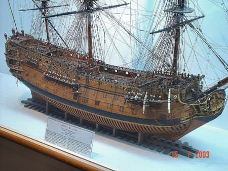
After finishing the santisima trinidad (07/2013)
it was time for a new adventure.
HMS Royal William
From Wikipedia and buildlog of KeithW
HMS Prince was rebuilt by Robert Lee at Chatham Dockyard in 1692, and renamed at the same time as HMS Royal William. During the War of the Grand Alliance the ship saw action at the Battle of Barfleur of 19 May 1692. The Prince belonged to the red squadron and carried the flag of Rear Admiral of the Red Sir Cloudesley Shovell. She was the first ship to break the French line during the battle.
Later she was rebuilt for a second time by John Naish at Portsmouth Dockyard from 1714, relaunching on 3 September 1719. She was laid up after her re-launch and saw no service at all until she was reduced to an 84-gun Second rate ship in 1756. One year later, she was part of an unsuccessful expedition against Rochefort led by Admiral Sir Edward Hawke. Her squadron, under Vice-Admiral Charles Knowles, attacked the Île-d'Aix and forced her garrison to surrender. In 1758 she participated in Boscawen's and Wolfe's attack on the French Fortress of Louisbourg (Nova Scotia) and an indecisive skirmish with a French squadron. The following year the Royal William returned to Canada under the command of Captain Hugh Pigot to join the attack on Quebec. After the Battle of the Plains of Abraham and the capture of Quebec she sailed back to England with the body of General Wolfe. In 1760 the Royal William was Boscawen's flagship when he took command of the fleet in Quiberon Bay. However, after a severe gale he was forced to return and shift his flag to the Namur. During the expedition against Belle Île of 1761 she was detached with several other ships to cruise off Brest and prevent a French counter-attack from there.
The Seven Years' War seems to be the last time that the Royal William played an active role. She was broken up in 1813.
LINKS TO RESOURCES
Euromodel website
- Royal William Product Page
- Interpretive Information by PiratePete
- Royal William Resource Information
Build logs on MSW
- http://modelshipworld.com/index.php/topic/7195-hms-royal-william-by-keithw-euromodel-172/ by KeithW- Royal William by VinceP (Euromodel)
- Royal William by Brian C (Euromodel)
- Royal William by Denis Pink (Euromodel)
- Royal William by Ersin Derebek (scratch)
- Royal William by Kay (scratch)
Other resources
- USNA model of Royal William
- Royal William by Victor Yankovitch, also alternative source.
From Wikipedia and buildlog of KeithW
I 'd seen Vic his Royal William on the forum Rcgroups, and the build was so wonderful that i knew that i must build this ship also.
After a dip in building boats over more then 1 year, i started the last month with the Royal William.
I used plywood 10mm for the false keel and the frames.
Behind the false keel was another boatbuild that failed. A swedisch privateer. Must remove the plans.- qwerty2008, seafarermiami, mtaylor and 5 others
-
8
-


![20210213_130211[1].jpg](https://modelshipworld.com/uploads/monthly_2021_02/1997902061_20210213_1302111.jpg.59cb4b6a258929ce43009ab0fb0fcb80.jpg)


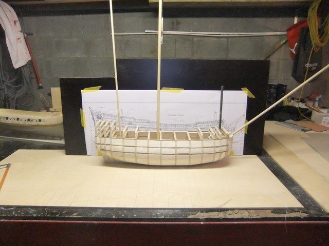
The Hayling Hoy 1760 by luc - 1:48 scale - First fully framed model
in - Build logs for subjects built 1751 - 1800
Posted · Edited by luc
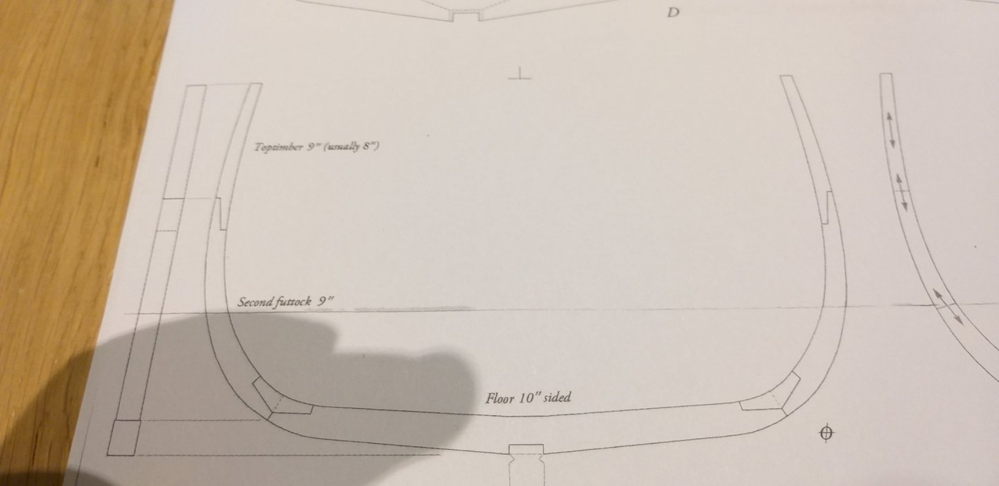
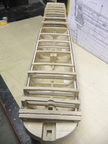
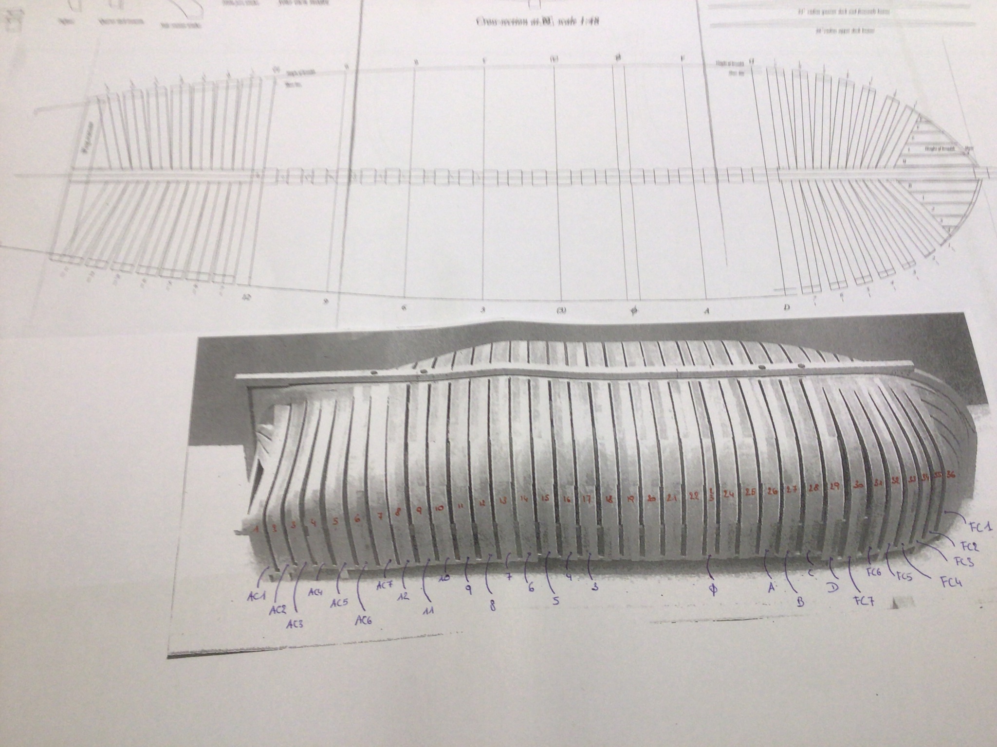
I have numbered the frames so that we can discuss the correct frameI think that:
frame 17, 18, 19, 20 = frame 3 on the drawings
frame 21 = frame 2 on the drawings
frame 22 = frame 1 on the drawings
frame 23 = frame 0 on the drawings
frame 24,25 = frame A on the drawings
what do you think ( the forum) ?