Clark
-
Posts
309 -
Joined
-
Last visited
Content Type
Profiles
Forums
Gallery
Events
Everything posted by Clark
-
No problem. The point is that you have to think about the next 10 steps when building the Reale.
- 112 replies
-
- 1
-

-
- corel
- reale de france
- (and 1 more)
-
Thanks Frank, the photo and my description my have led to errors but I have just drilled the water outlets, the slots for the shrouds are probably led through holes in the outer gangway. I will keep your hint in mind. Clark
-
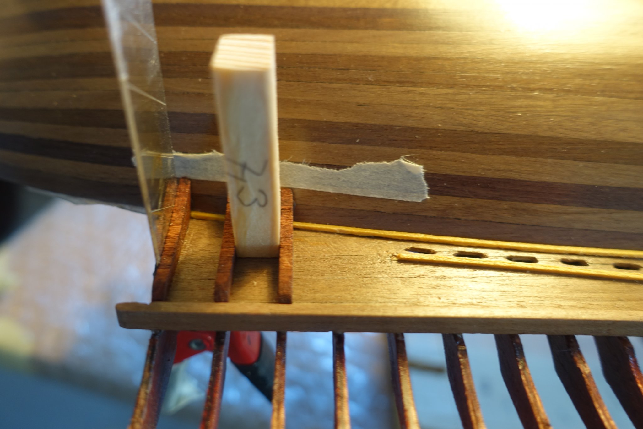
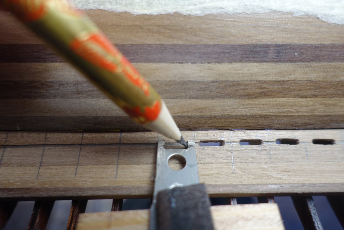
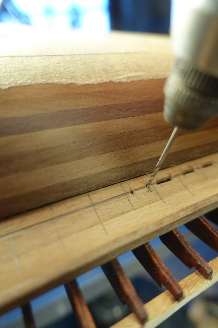
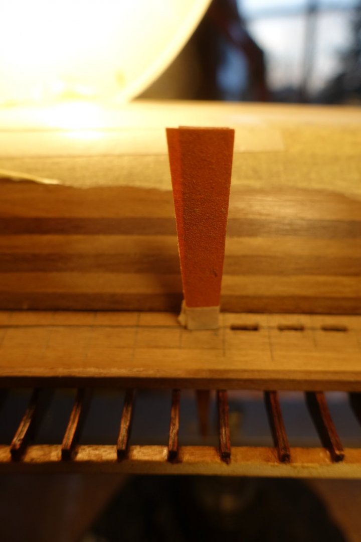
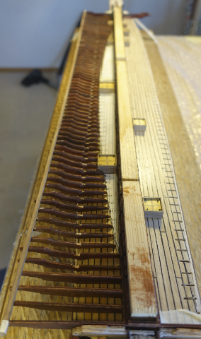
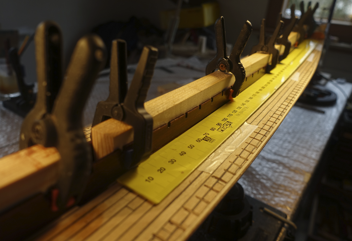
Lower planks are glued now and I have started to drill the holes for water outlet. I made some help lines. One line 3 mm distance to the hull to mark the middle of the holes. Rectangular ones to mark the location of the supports. Distance between the rectangular lines was 9.5 mm. Thus, I made a small metal template, outer width 9.5 mm with an inner opening of 6 mm to mark the limits of the holes. For drilling the holes, a driller 0.8 mm was used, wood between the holes was cut and sanded. 6 mm width was marked on the sander (sanding paper glued on wood piece). To arrange supports for the lower planks, I started with the first one arranged by a metal strip clamped to the yolks. Gap between the following supports was kept by using a wood block with 7.3 mm thickness

- 112 replies
-
- 3
-
-
- corel
- reale de france
- (and 1 more)
-
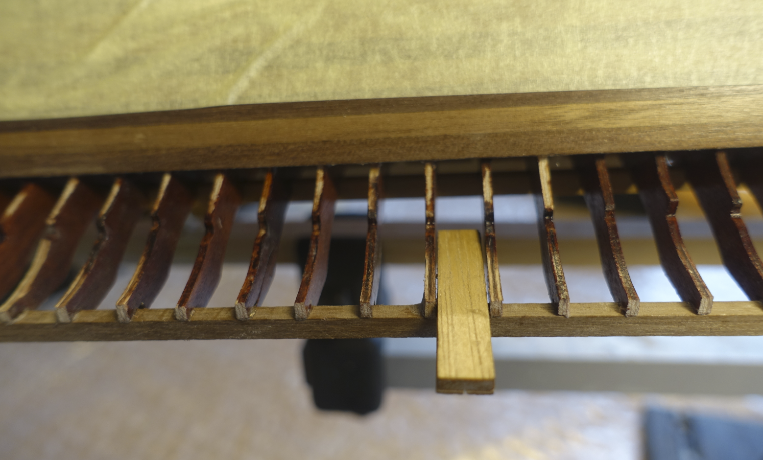
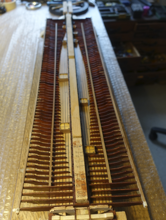
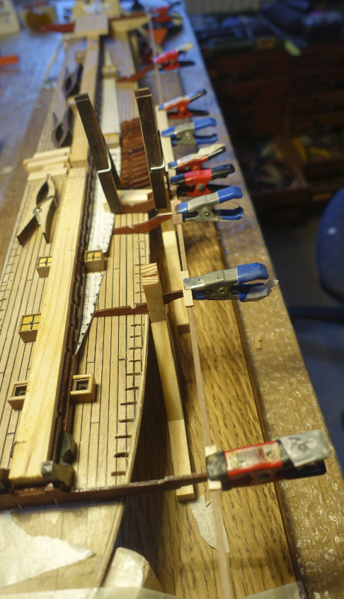
Supports of port side and starboard side are now all fixed. Outer ends of supports had to be corrected in height.

- 112 replies
-
- 2
-
-
- corel
- reale de france
- (and 1 more)
-
Frank, it is a pleasure to see your progress and the effort you are putting into the details. I noticed that you did not install the cannons yet. This because you wanted to finish the front deck first? Clark
-
Thanks Frank, when I first read your blog I was astonished that only a limited number of supports can be adapted per day. Now I know what you meant. Hope to read further inspiring news in your blog. Clark
- 112 replies
-
- 1
-
-
- corel
- reale de france
- (and 1 more)
-
All supports of port side are now fixed. It really took some time.
- 112 replies
-
- 3
-
-
- corel
- reale de france
- (and 1 more)
-
With every new ship fun and effort in rigging increased. Doing the same knots again and again can be very relaxing after a hard day. When I began to build mediterrian ships, the task increased further since the plans and books showing the rigging are limited. Looking in the old paintings is sometimes not helpful. Comparing the rigging plans of Corel and Amatis Xebecs let me suppose that there is still a lot of variation possible. Clark
-
Hi Chuck I was happy to find your blog. Klaus Störtebecker is still a hero in Germany at least at the coast line. As far as I know, the ship is originally named "Toller Hund" : "Toll" has two meanings: mad and great. Klaus Störtebecker was both. Clark
- 130 replies
-
- 4
-
-
- wütender hund
- hanseatic
- (and 2 more)
-
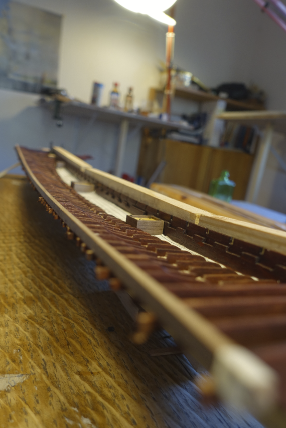
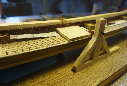
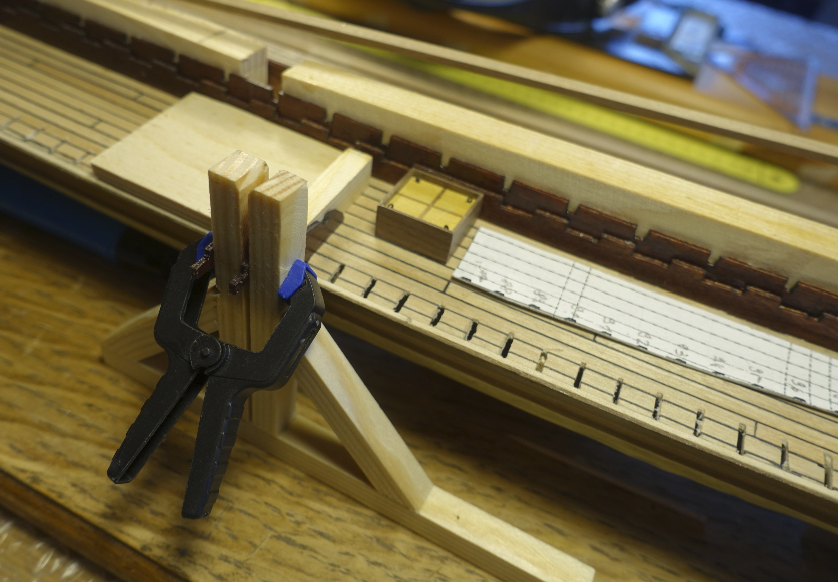
As suggested by the Corel manual, I started with the two middle supports #82 and #83 (Corel plans), which are at the lowest point of the deck line. To get them in a vertical position I made a holder with a 1.5 mm slot (= thickness of plywood) and 8 mm width of the vertical wood strips (= distance between the supports). I made also some wood pieces 8 mm wide to keep and control the distances between the supports. Additional supports were added between #82 and #83 and the yokes. Further supports were inserted between the middle ones and the yokes.
- 112 replies
-
- 3
-
-
- corel
- reale de france
- (and 1 more)
-
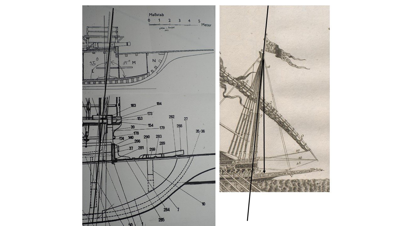
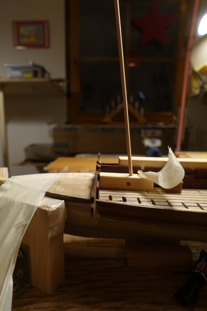
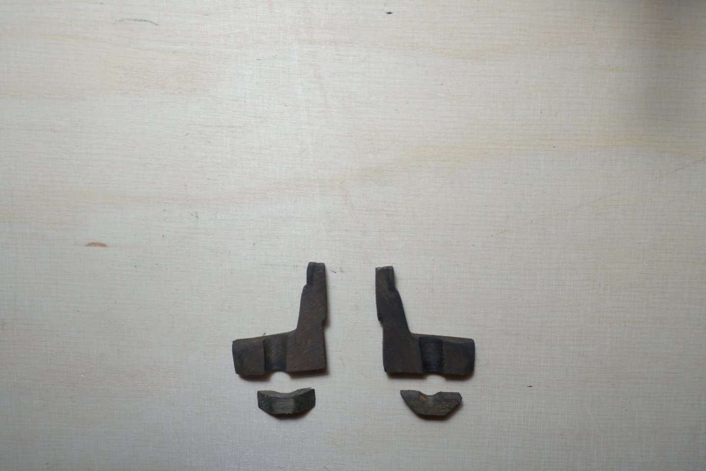
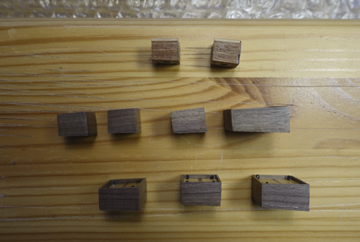
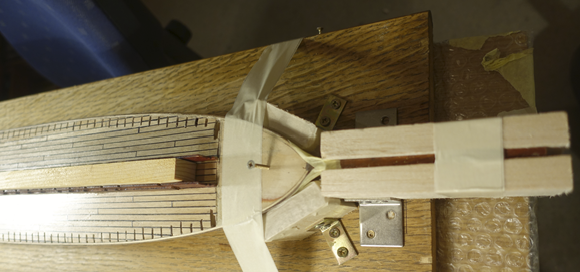
Regarding the bitts for fixation of the foremast; I had a discussion with Frank (fmodair) some time ago. Pictures of La Reale and some of other galleys show that there is a deviation of 5-7 degree of the foremast from the vertical axis due to the special handling of the lateen sails. It declines toward the bow. In the Corel plans, the foremast is shown in a vertical position. I decided to follow the paintings and drawings. To follow them, the deviation of the foremast of the vertical axis has also to be reflected in the tube to be drilled into the bitts. I have tested the decline with some wood pieces simulating the bitt and the foremast. Moreover, I do not believe that the bitts were strong enough to withstand the enormous power of the big sail, i.e., the foremast had to fixed at the keel line. Such a fixation is also shown in the Mondfeld plan of the galley La Dracene. Thus, I made surroundings for the foremast fixation. Next step is adapting the supports for the oars., which is probably the most difficult part
- 112 replies
-
- 2
-
-
- corel
- reale de france
- (and 1 more)
-
Some recommend to mix the paint with PVA to get an uneven result. I am eager to read the news on your post.
- 510 replies
-
- 1
-
-
- reale de france
- corel
- (and 1 more)
-
Frank, which kind of paint do you want to use? Water based paint would not work, I assume. May be better to use Humbrol or any other enamel paint. But I am not sure if the sanding procedure proposed works together with this kind of paint. Any experience? Clark
- 510 replies
-
- 1
-
-
- reale de france
- corel
- (and 1 more)
-
Glad you are back. "Notebook" is an excellent idea. Clark
- 510 replies
-
- 1
-
-
- reale de france
- corel
- (and 1 more)
-
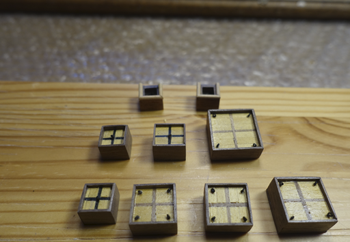
When building the hatch coamings, I put the lids at a higher position than recommended in the Corel plans. Regarding the coamings for the anchor line, it should probably only protect the hole in the deck from water flooding in. Nevertheless, the rope would be damaged if pulled along the edges. Thus I added a protection. The hatch coamings had to be tapered due to the sloping deck line in the line from the middle to the hull. It is necessary to keep the upper line of the hatch coamings horizontal since the footplates of the oarsmen will be attached later. To put the coamings in place, ship had to fixed. Hull was protected with painter tape. Ship was put in the slipway, levelled again and fixed by balsa/foam supports. Since I was afraid that the long stem post might get broken (it is really a long and small hull), it was covered by balsa pieces.
- 112 replies
-
- 2
-
-
- corel
- reale de france
- (and 1 more)
-
Thanks a lot, Frank. Did you have the chance to get back to the bench? I am eager to read news of your progress. Your report is more than inspiring. Clark
-
I decided to reseal the hull. I sanded it (grade 120, 180, 320) which took me about one week. It is really not the job I like. After sanding, I sealed it with the water based diluted (~20% H2O) acrylic varnish. Corel material of the supports for the middle gangway and thwarts is made of plywood. The best way may be to replace them by normal wood. I relied on the ones provided by Corel. I stained them mahogany to cover the plywood character a bit. Next step is building the hatch coamings.
- 112 replies
-
- 3
-
-
- corel
- reale de france
- (and 1 more)
-
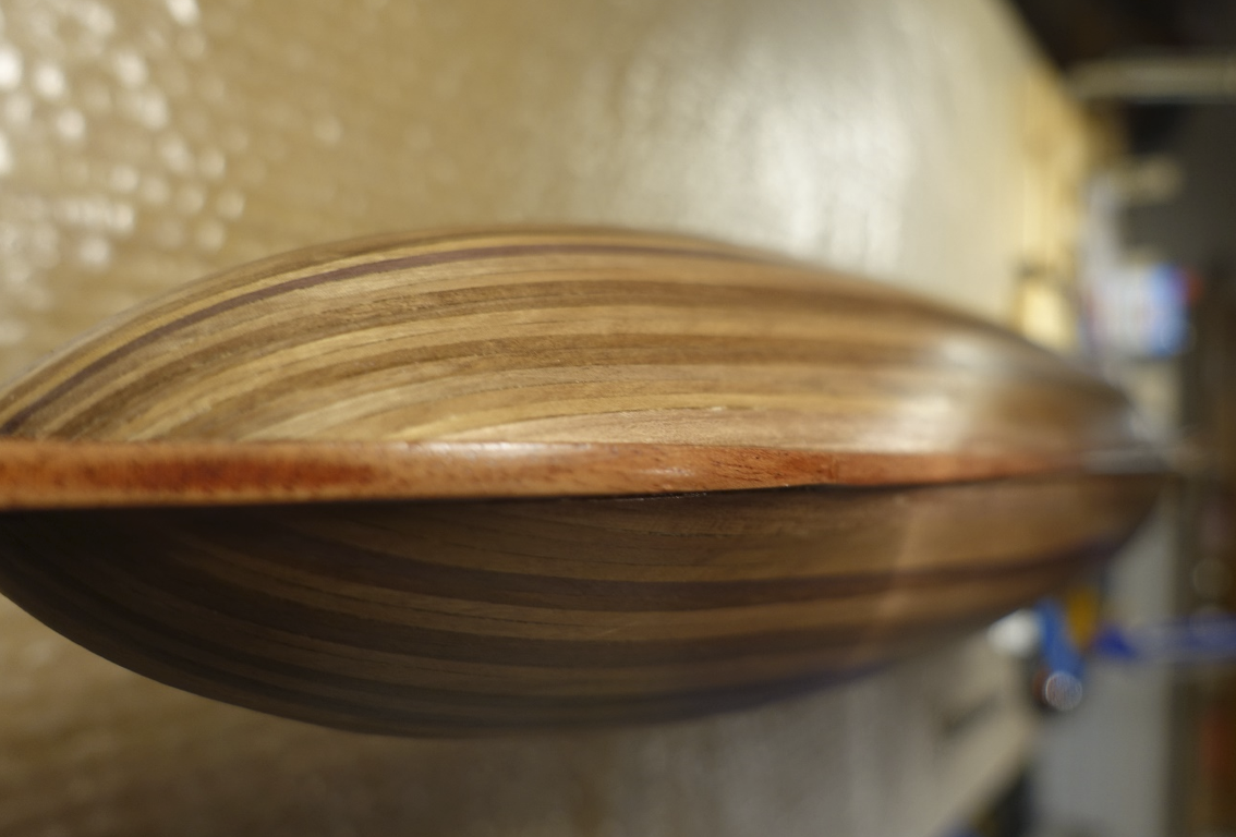
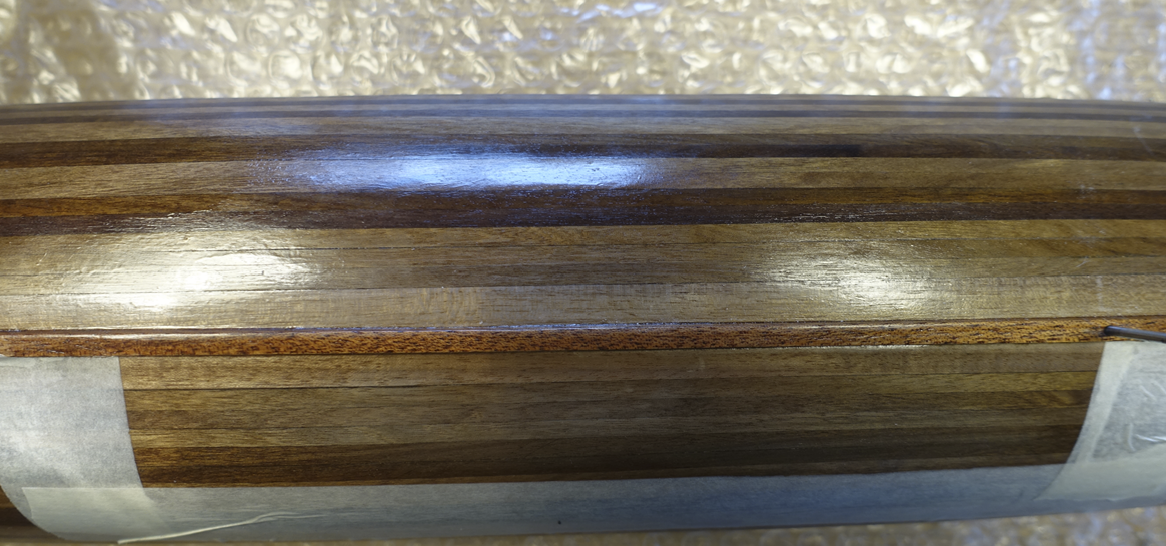
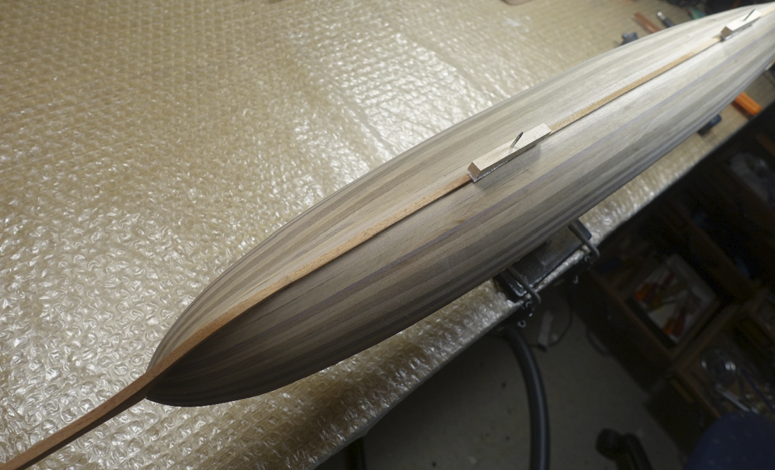
Meanwhile I have tested other varnishes and oils on walnut pieces. Finally, I found one on acrylic basis and tried it on part of the hull sanded. In the photo below, the glossy varnish (Nelson) can be seen on one side and on the other side the acrylic one (water diluted/surrounded by painter tape) on the other side . I will put the ship aside and have another glance on it.
- 112 replies
-
- 5
-
-
- corel
- reale de france
- (and 1 more)
-
When starting the Reale, I shortly hesitated to paint it to get nearer to the orignal one. It is probably a never ending discussion if wood ships should be painted or not. I am a fan of the wood structure, thus I will probalby stain only the plywood pieces.
- 112 replies
-
- 2
-
-
- corel
- reale de france
- (and 1 more)
-
I like the wood structure to be visible. Thus I only want to seal the wood with varnish. Im will probably sand the old varnish down. Clark
- 112 replies
-
- 1
-
-
- corel
- reale de france
- (and 1 more)
-
Hull was covered with diluted mat clear varnish (Nelson). I have tested the varnish on several pieces of wood before. I was a bit shocked after the drying of the varnish. The hull is much too glossy. Have to think about.
- 112 replies
-
- 1
-
-
- corel
- reale de france
- (and 1 more)
-
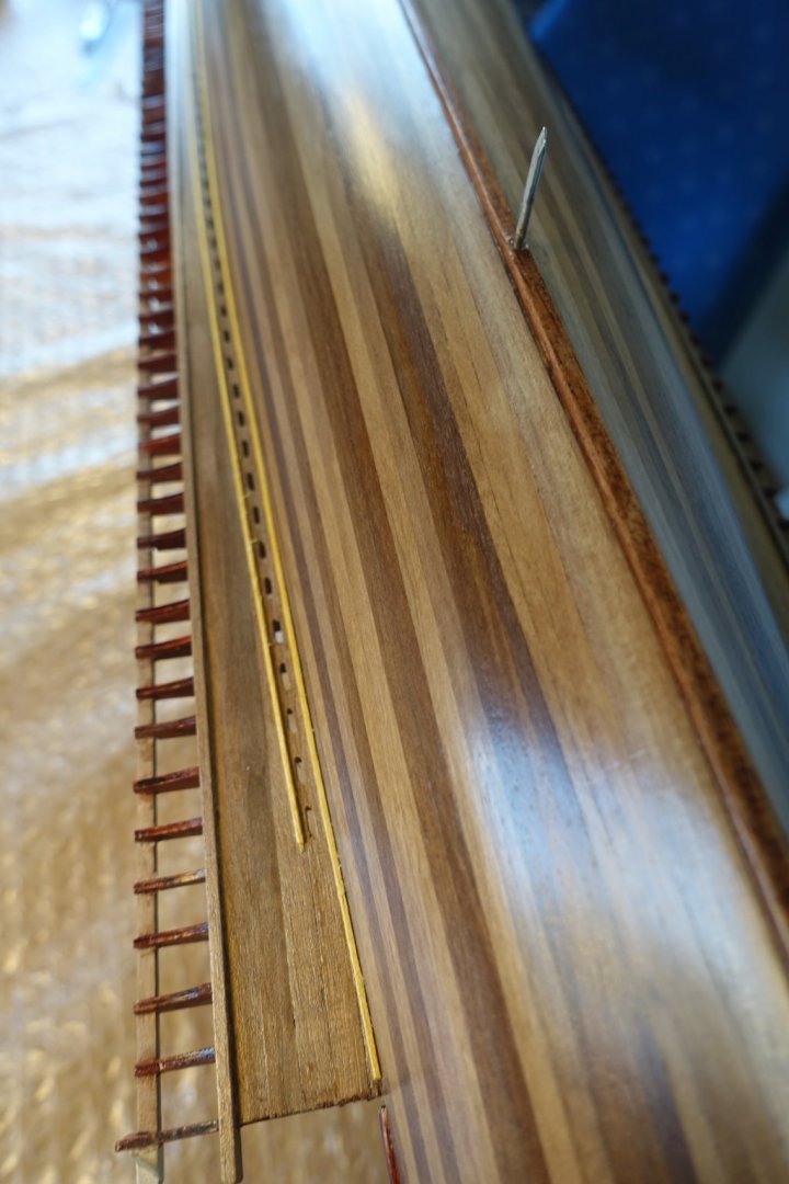
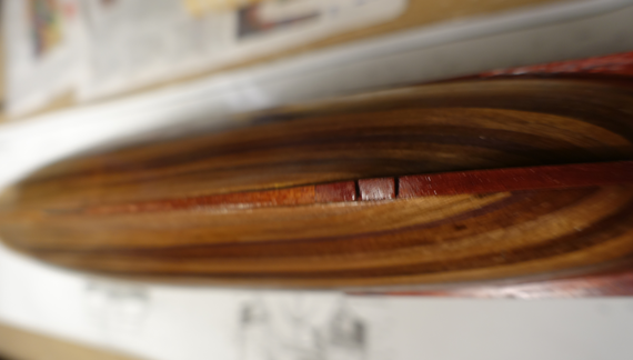
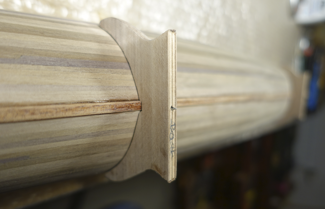
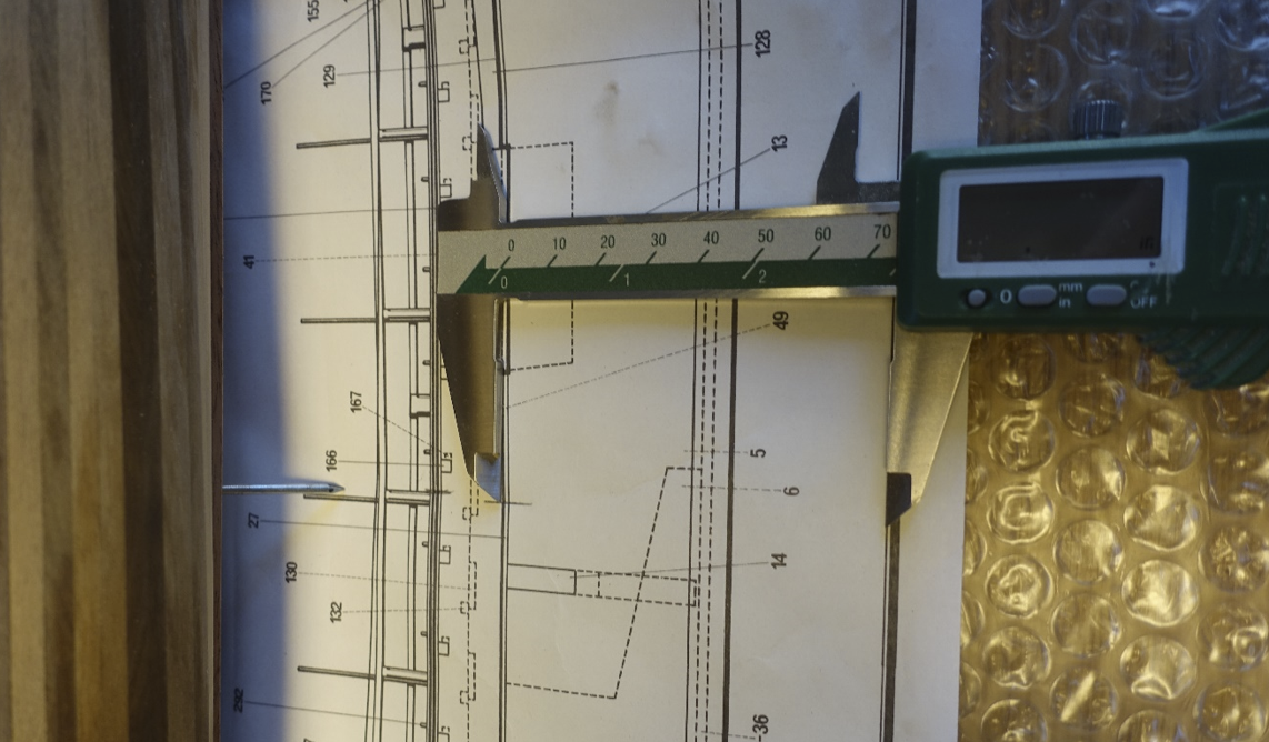
Not much progress in the meantime. But the kit and plans urges one to think not only about the next two steps. Shortened nails were put into the keel for the (much) later fixation of the ship in the final supports. Final supports were already dry fitted since this will probably much more difficult with all the stuff on the deck. Final supports provided by Corel were covered with walnut strips on all sides to hide the plywood character. However, I am not sure if I will really use the Corel supports at the end. Final supports were also adjusted with the ship on them. For levelling in the longitudinal axis, the difference in height between the two support points was extrapolated from the Corel plan. Same points measured on the ship when put on the supports had only a small greater difference (~0.5 mm) than in the plan. I did not correct it. Levelling in the vertical axis (starboard / portside) was a bit more tricky and done with the help of spirit levels and caliper. Wood/foam supports were adapted for following mounting and fixation in the slipway.
- 112 replies
-
- 3
-
-
- corel
- reale de france
- (and 1 more)
-
You mean the curve from stern to bow? It may be the best to test the bending proceeder on an extra plywood piece. Usually wood can be bended by applying heat. If the wood is watered, the water helps to spread the heat. I am not sure how plywood reacts. Clark