Clark
-
Posts
310 -
Joined
-
Last visited
Content Type
Profiles
Forums
Gallery
Events
Everything posted by Clark
-
Hi Frank, Most of the glue types will probably ve visible under the Mica. Do you have ever tried acrylic glue to be hardended by UV light which is very transparent at least to my experince. I do not know if it works with Mica and wood. Clark
- 510 replies
-
- 1
-

-
- reale de france
- corel
- (and 1 more)
-
I was also wondering about the handling of the rudder tiller. Not only because it stretches into the kings area but also because it is very short. I would assume that there is a huge horizontal energy with the waves wich would it make very difficult to handle such a short tiller. Maybe there were additional blocks and ropes used to enhance the leverage. Is there anything outlined in the plans of Fleur de Lis about the rudder? Clark
-
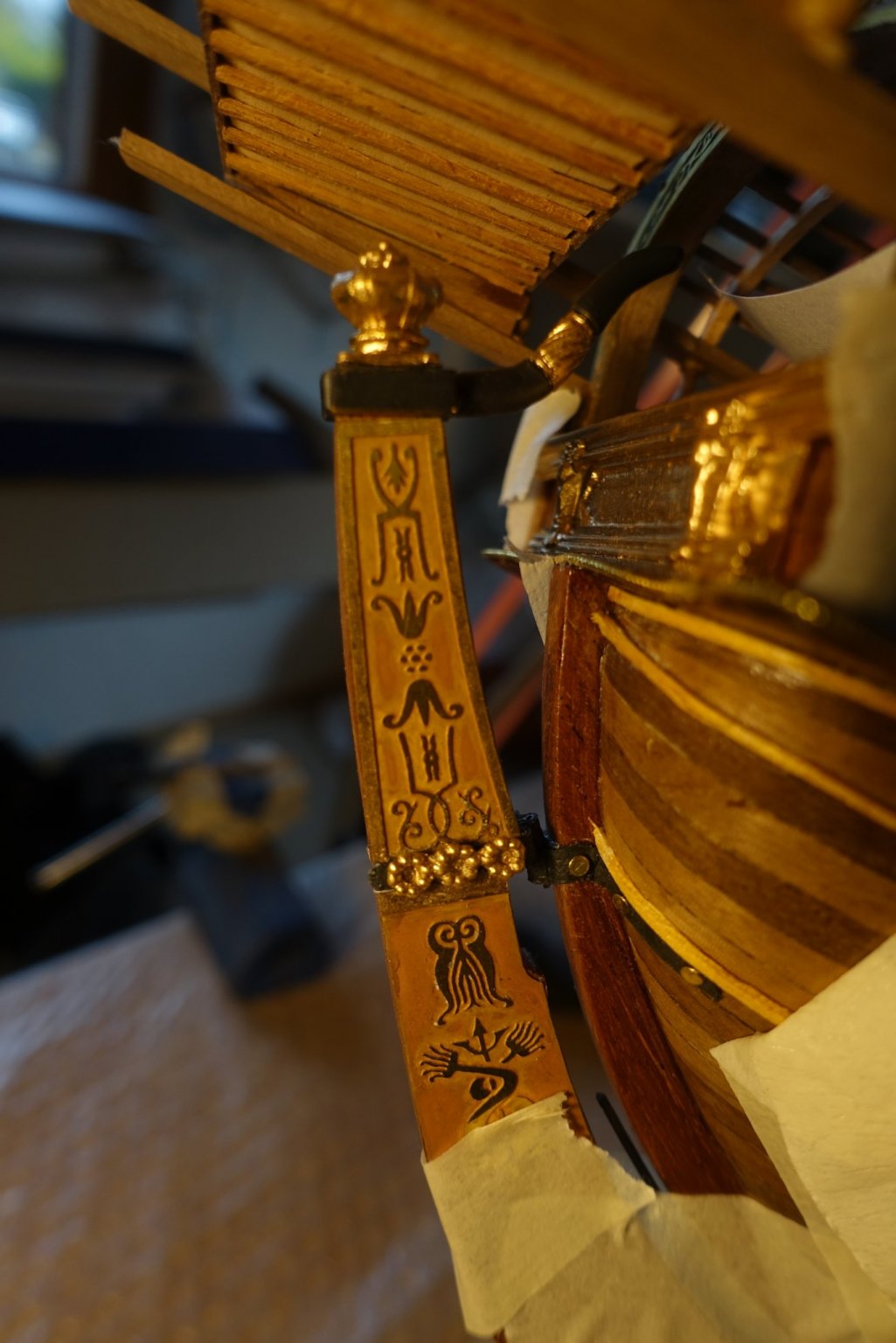
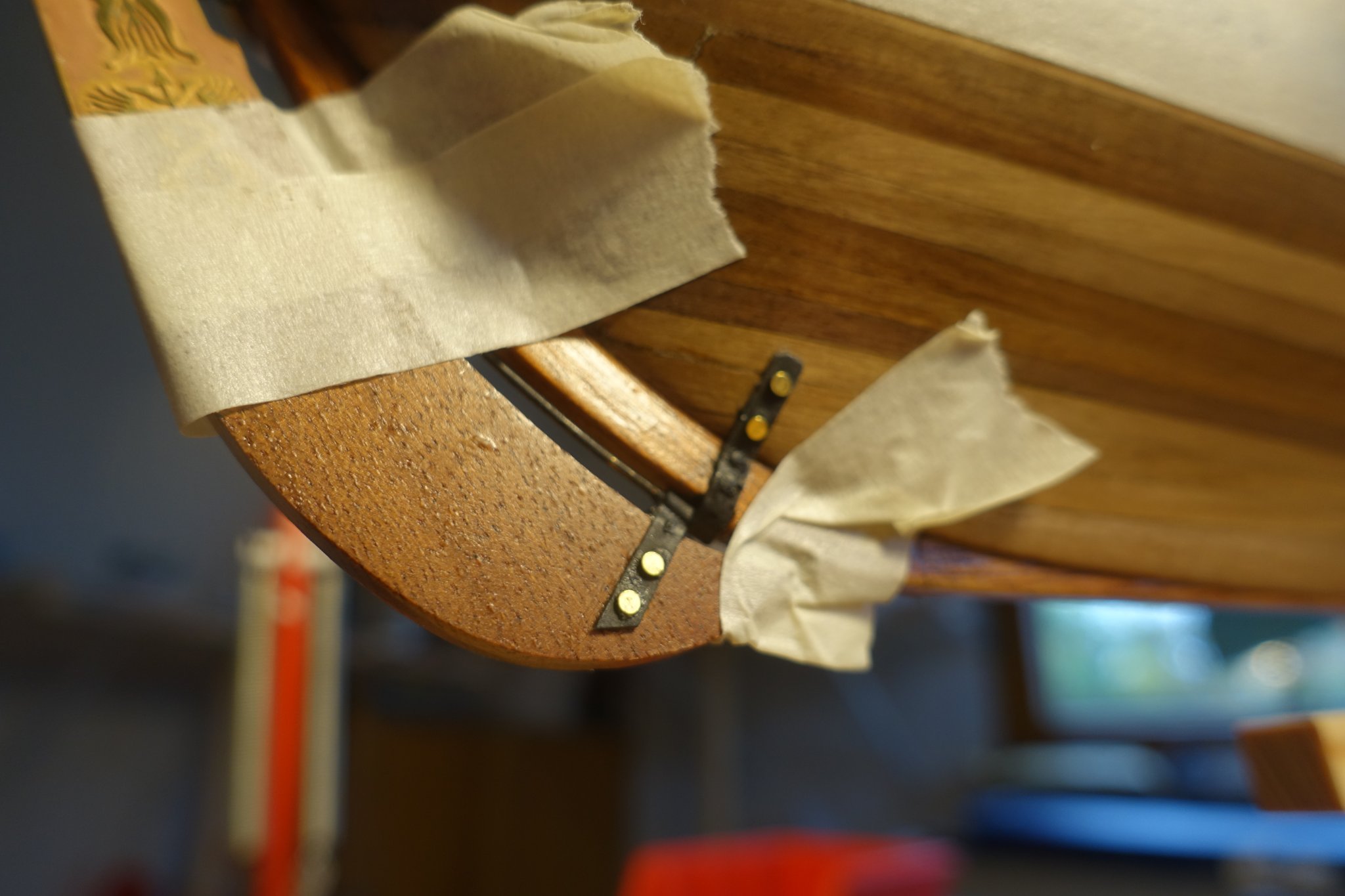
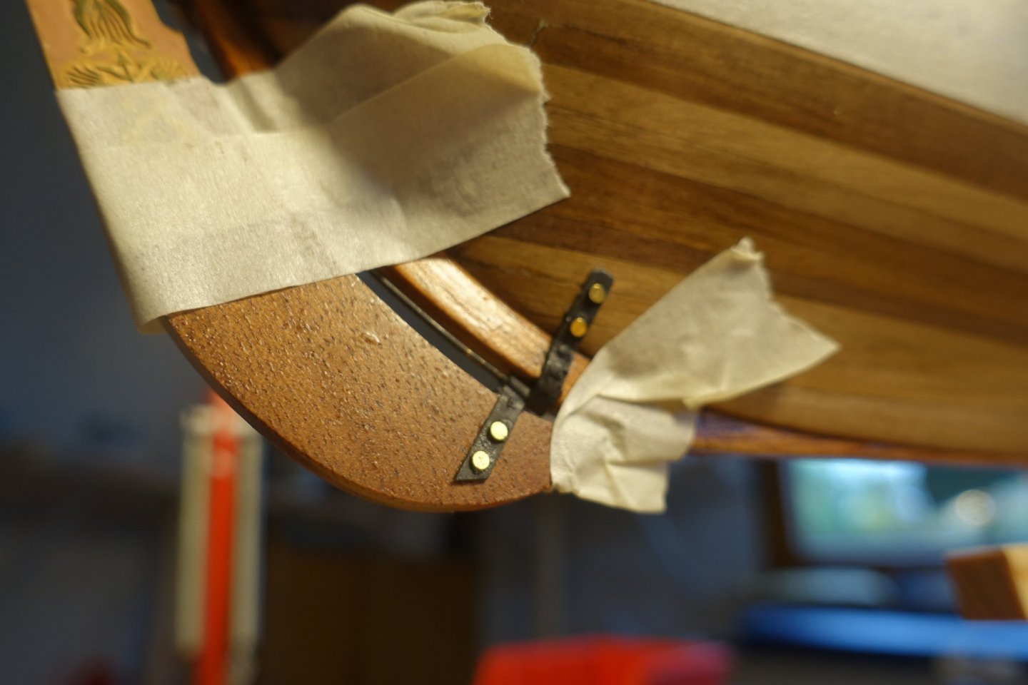
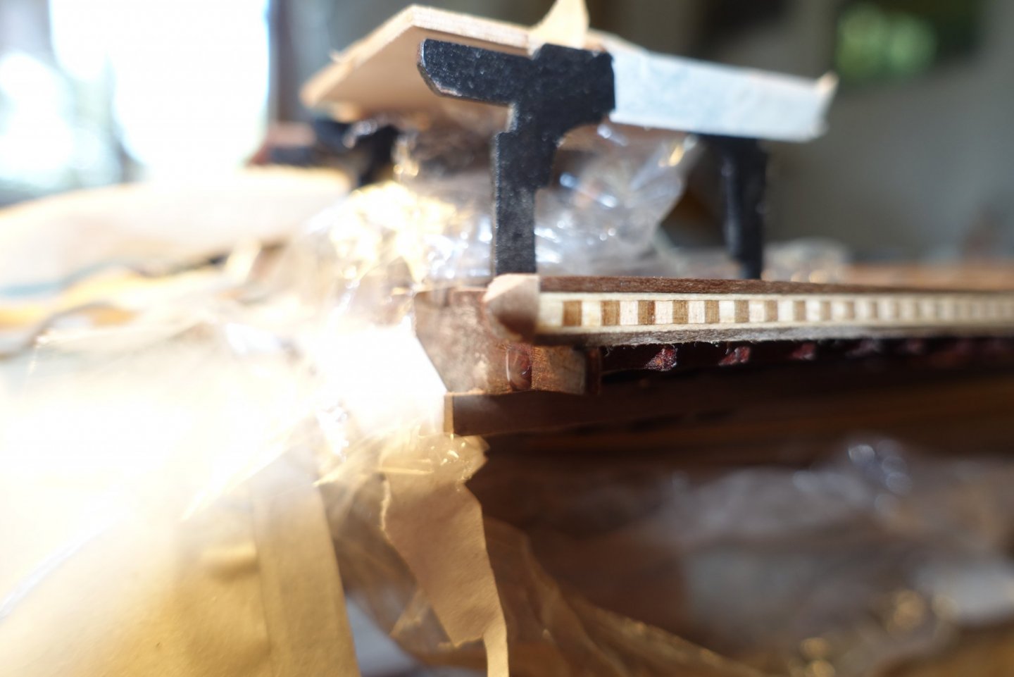
Thanks, Frank, for accompanying me. Maybe I made the mistake that I left the brass pieces too long in the blackening solution. They broke immediately when I tried to adapt them finally to the rudder. They were preadapted before putting them in the blackening solution. Although the upper hinge seemed to resist the blackening solution, I replaced it also by card strips to get a uniform appearance (photo below). It may be better to paint the hinges with email paint and not to use blackening solution.

- 112 replies
-
- 3
-
-
- corel
- reale de france
- (and 1 more)
-
The brass pieces provided for the rudder hinges did not resist bending and blackening at least the way I did. Thus I replaced them by card strips. Stern part is now ready and I will proceed with the bow area.
- 112 replies
-
- 3
-
-
- corel
- reale de france
- (and 1 more)
-
It really took some efforts to get the bending. Your way may be better. Luck and patience. Clark
-
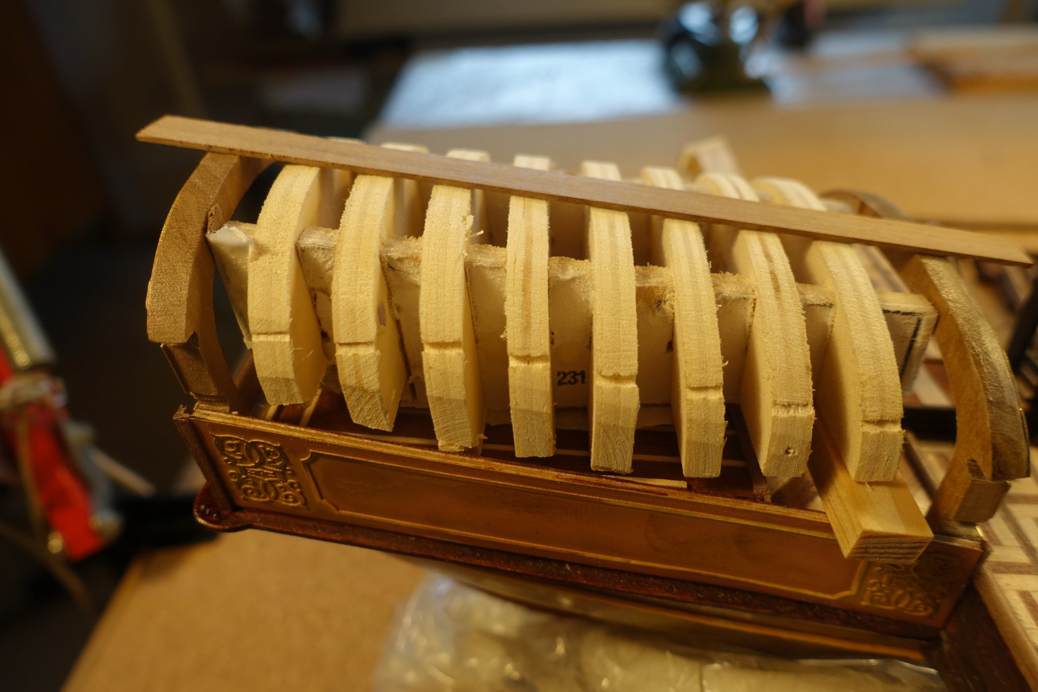
For adapting the arches covering the kings platform, I used and sanded the template provided by Corel before proceeding the way Corel manual suggests. This because the arches had to be put in line with the arches already glued at the stern platform. It took some time but it was the best way to fit the strips. Railings were fixed before putting the arch construction on. According to Corel there should be a window line between the railings: So far none of the Reale builders (fmodajr, bender, gimo) liked it. Me neither. I replaced it by some pillars.


- 112 replies
-
- 3
-
-
- corel
- reale de france
- (and 1 more)
-
Hi Frank, I am almost at the same point you are now. When building the Xebec, I had the same problem but used the flexible wood and it worked, althought it took a lot of efforts to bend the ends. Nevertheless, stressing of wood was no problem. Thus I will probably rely on the the flexible ones. For that purpose, I checked the templates of Reale Corel provides (#233 and others). They are not completely in line when placed in order and have to be sanded. Did you have the same problem? I am a bit disappointed of the Corel material. Your solution seems much better than the flexible wood. Clark
-
Frank, I was also wondering how to manage the problem of windows since they are visible from the outside only. Moreover, the false windows provided by Corel do not look very realistic. I do not like them. I will probable leave the space between the rails completely free. At present we all are watching the battle in your Country which will surely have a strong impact on Europe. Clark
- 510 replies
-
- 2
-
-
- reale de france
- corel
- (and 1 more)
-
The floor will be covered by arches but I know that is there. Thanks for stopping by. Clark
-
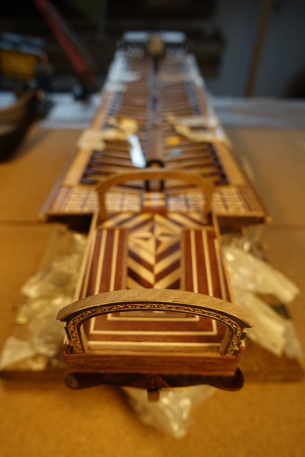
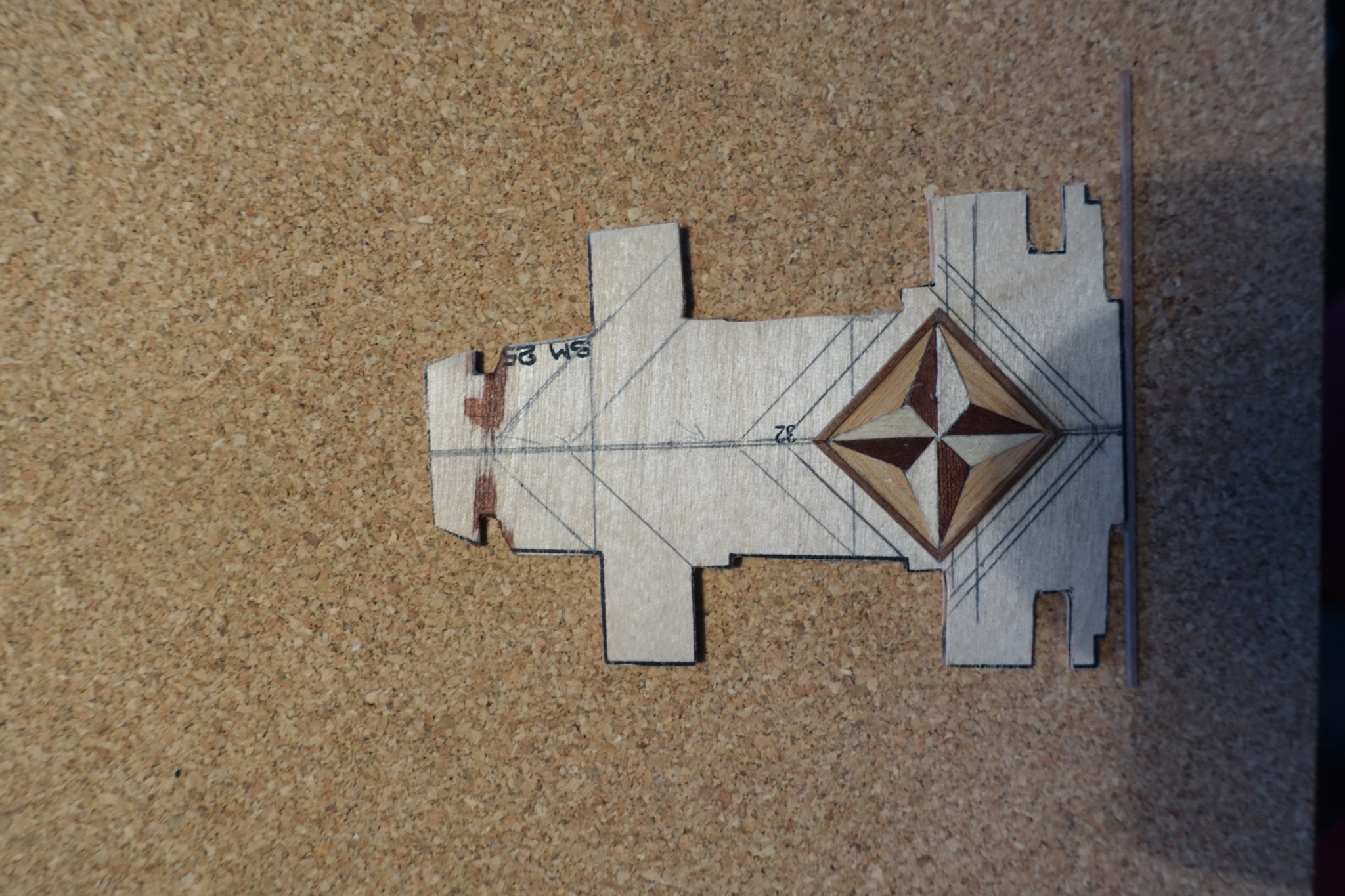
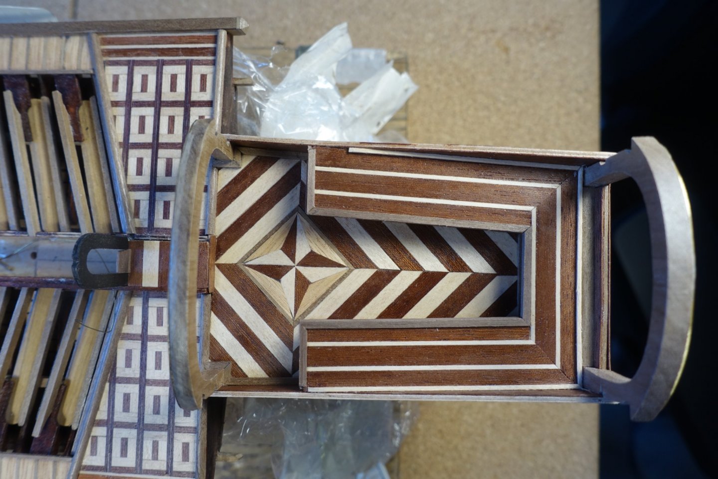
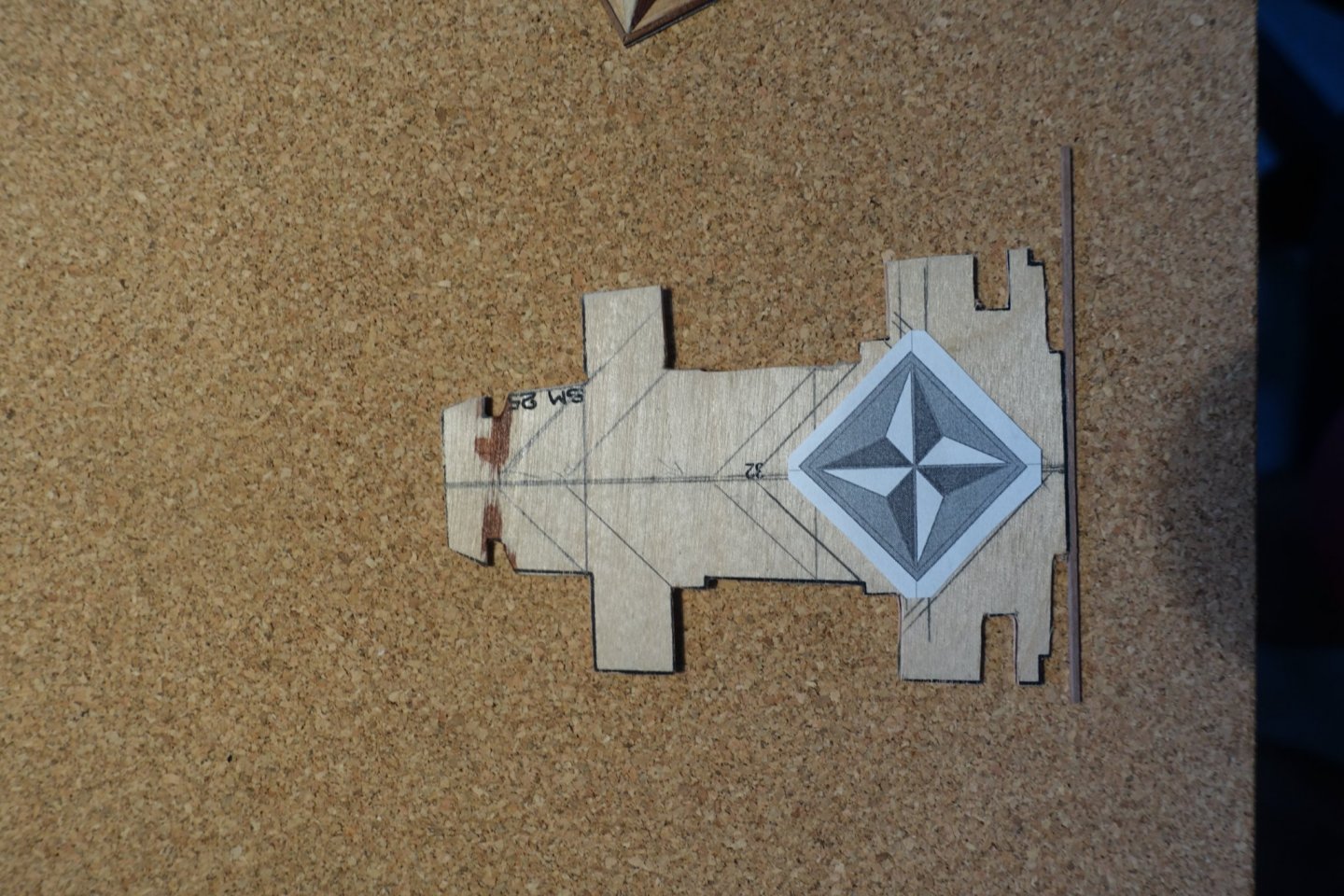
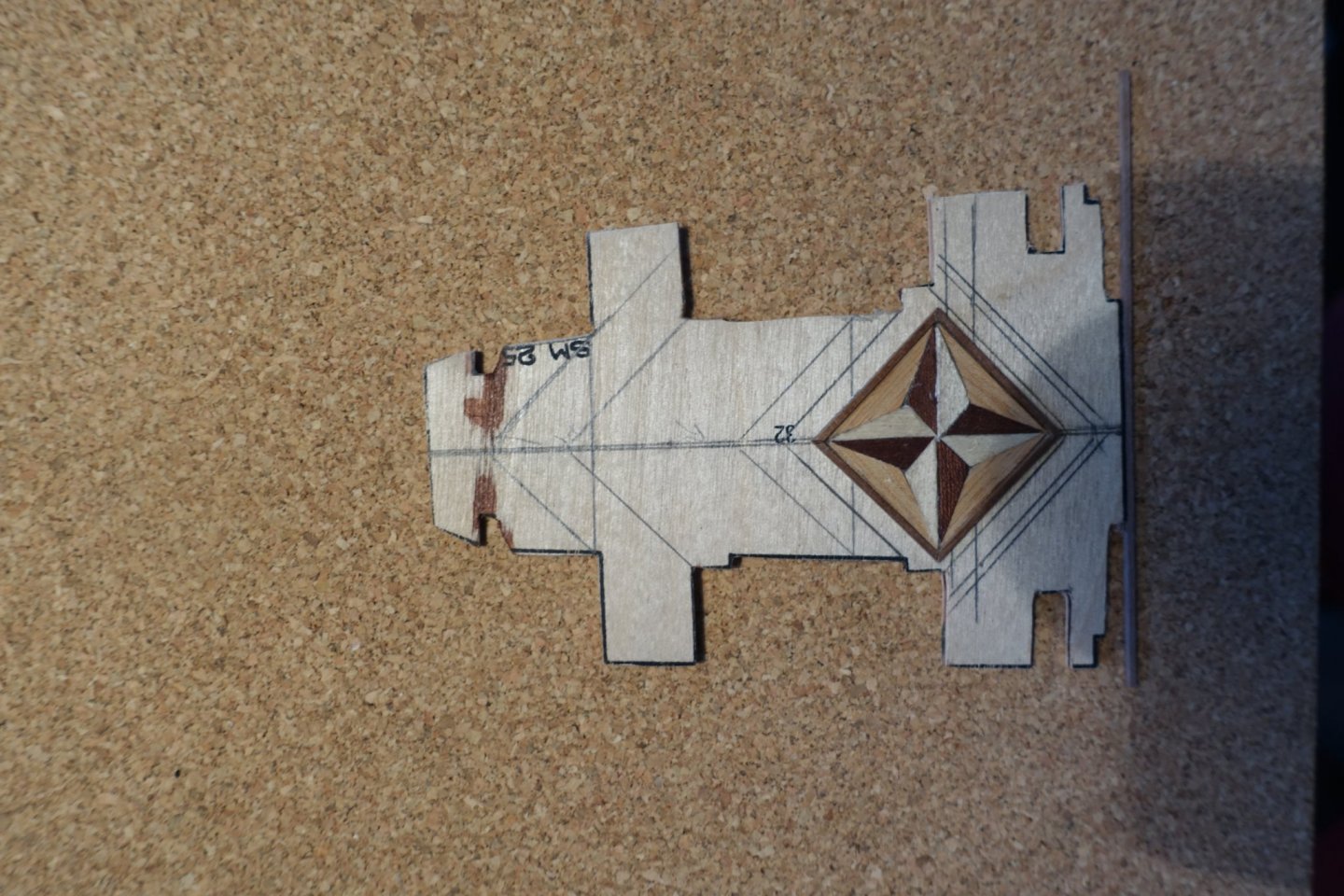
The king’s platform at the stern is ready. Compass symbol is surrounded by diagonal planking using mahogany and lime strips.

- 112 replies
-
- 4
-
-
- corel
- reale de france
- (and 1 more)
-
For planking the decorative platforms at the stern, I used the material provided by corel. Since these platforms were the beginning of the officer’s part of the ship, I marked the “border” to the oarsmen part by a half round strip on the top and a concave one at the bow side. Clark
- 112 replies
-
- 3
-
-
- corel
- reale de france
- (and 1 more)
-
Thanks for the excellent description and the ideas you are putting in your model. I will probably copy some of them if you dont mind. Regarding the length of the ship, I had already a discussion with my my wife were to place it. Discussion is not ready. Again thanks for the detailed description. Clark
- 510 replies
-
- 1
-
-
- reale de france
- corel
- (and 1 more)
-
Thanks, I will probably proceed with the mahogany planking. Clark
-
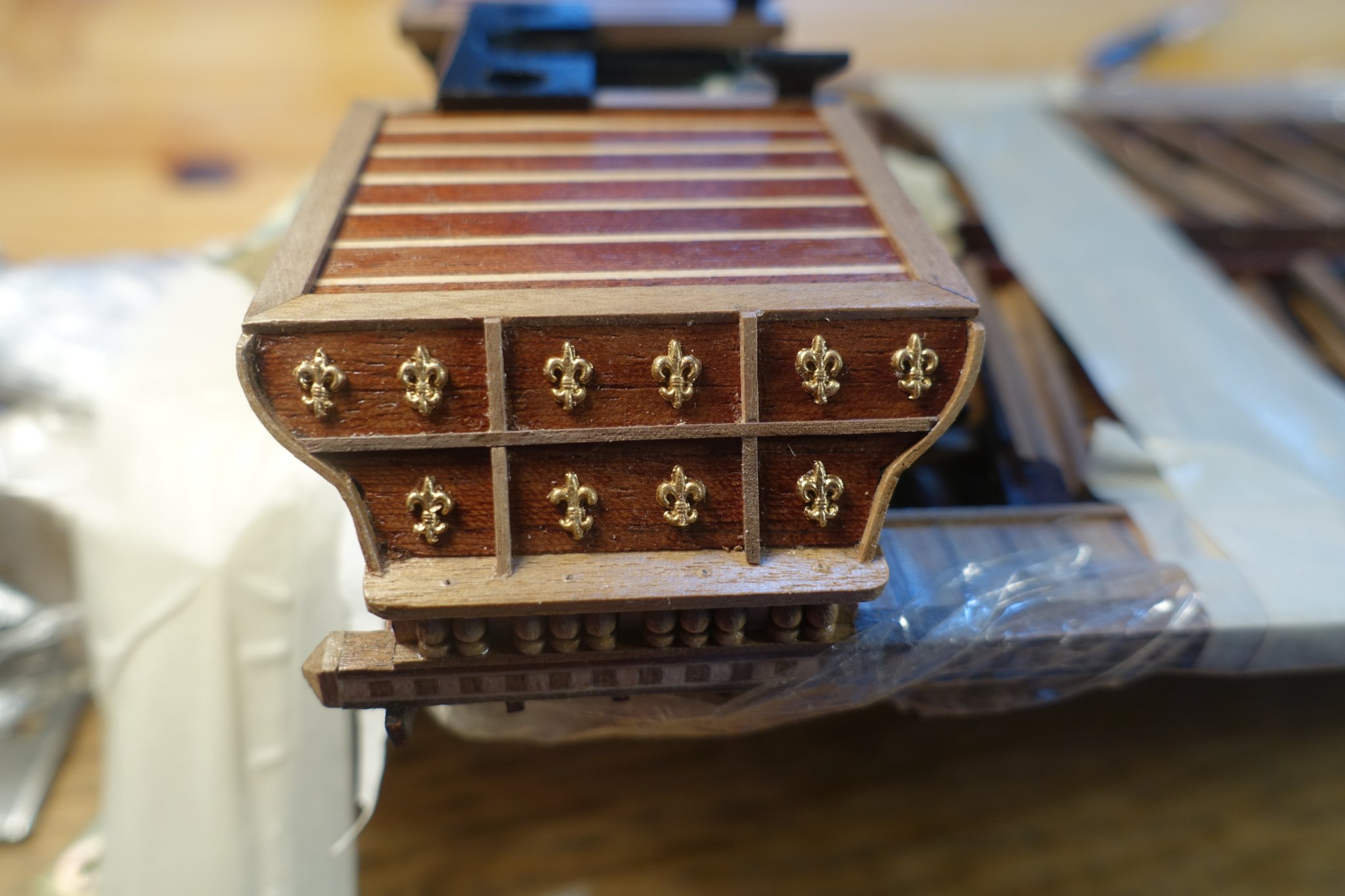
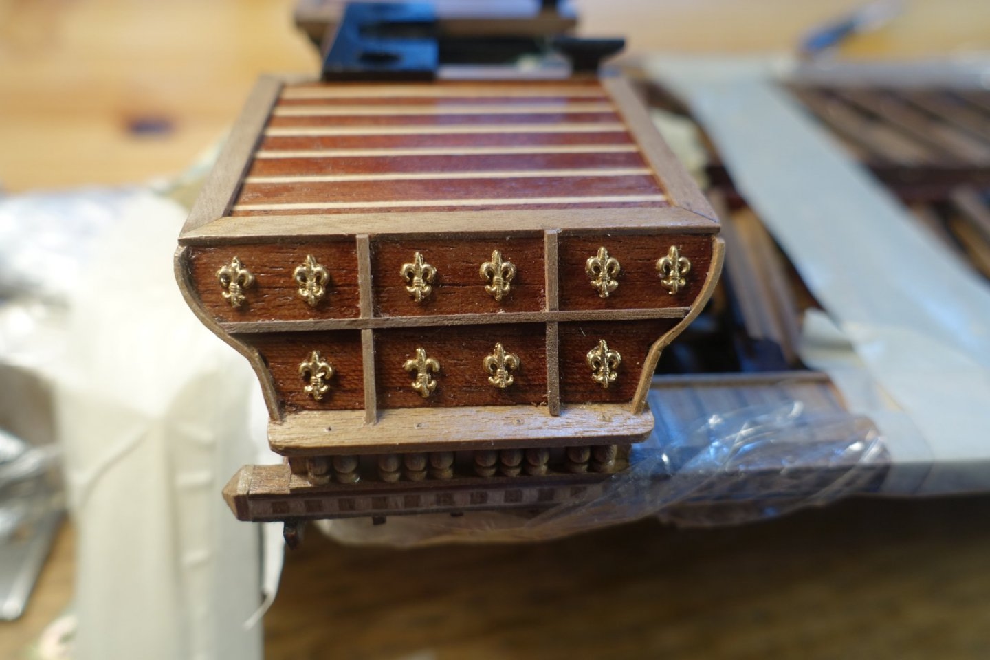
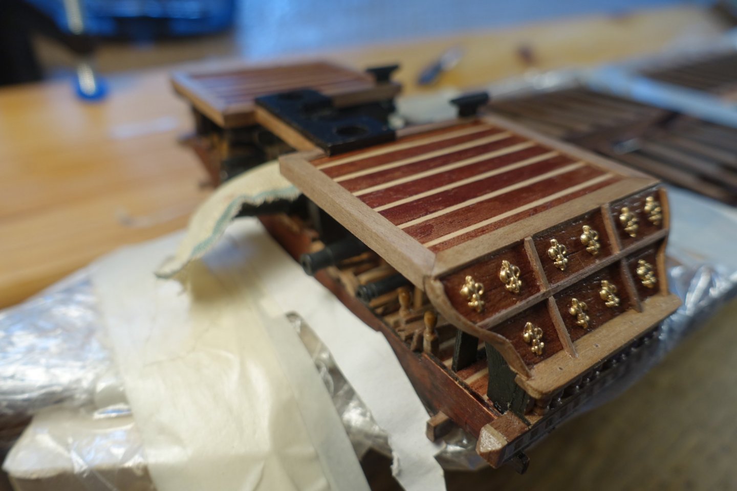
Forecastle with upper platform is ready. I used mahogany planks to get a contrast to the gangway of the oarsman und the lilies ornament. Unfortunately, it also makes the sander dust more visible.
- 112 replies
-
- 4
-
-
- corel
- reale de france
- (and 1 more)
-
Thanks also for the inspiration. Is the Coureur you are building, the one of CAF/Tom? I am thinking about the next project. Clark
-
I read the build log of Gimo who built the Reale back in 2013. He showed a nice suggestion to pep up the stern (kings?) platform. I also thought about planking the stern platform and decided to put a compass symbol on it, remaining planking has to be done in a diagonal shape. Template was drawn using Power Point.
- 112 replies
-
- 3
-
-
- corel
- reale de france
- (and 1 more)
-
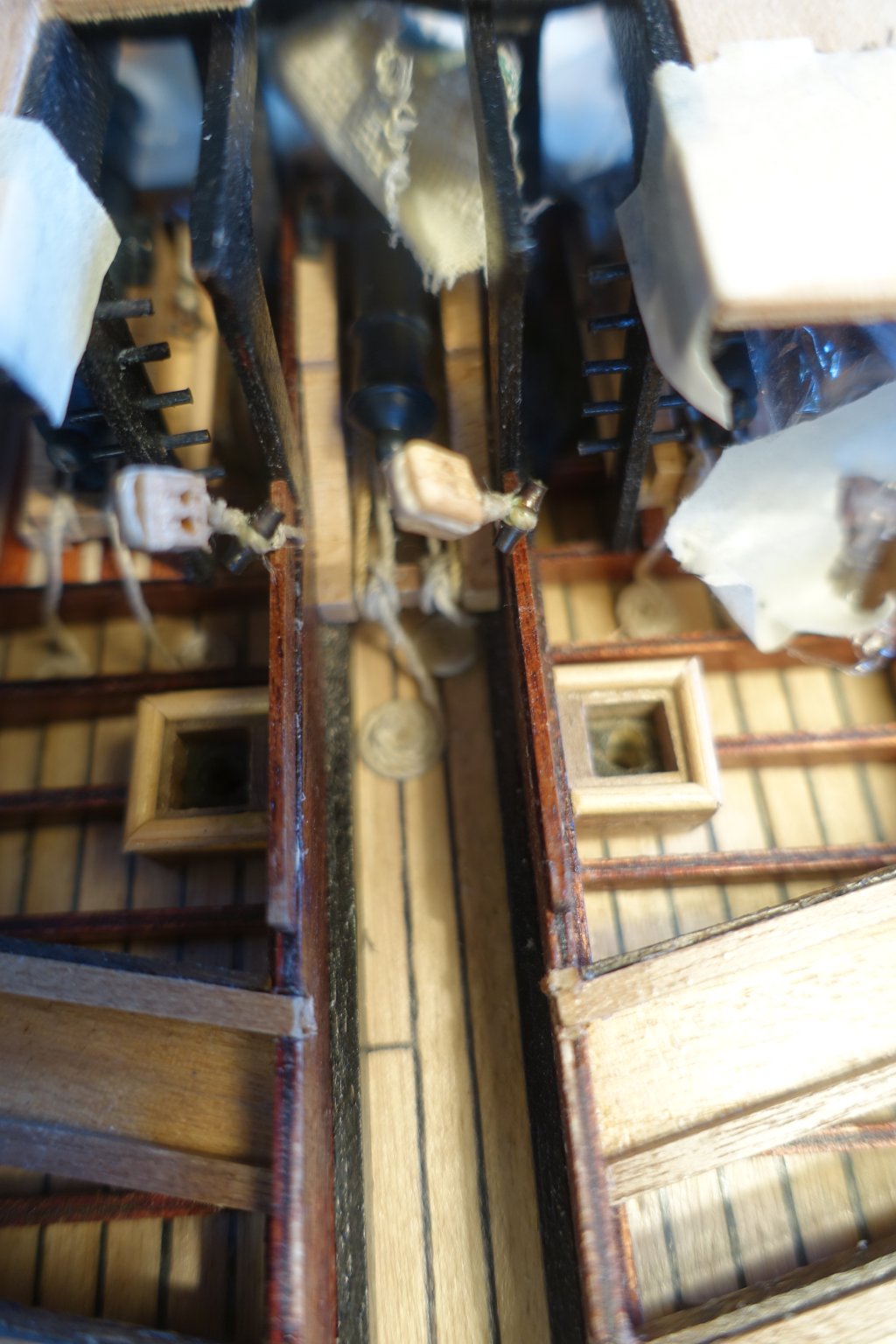
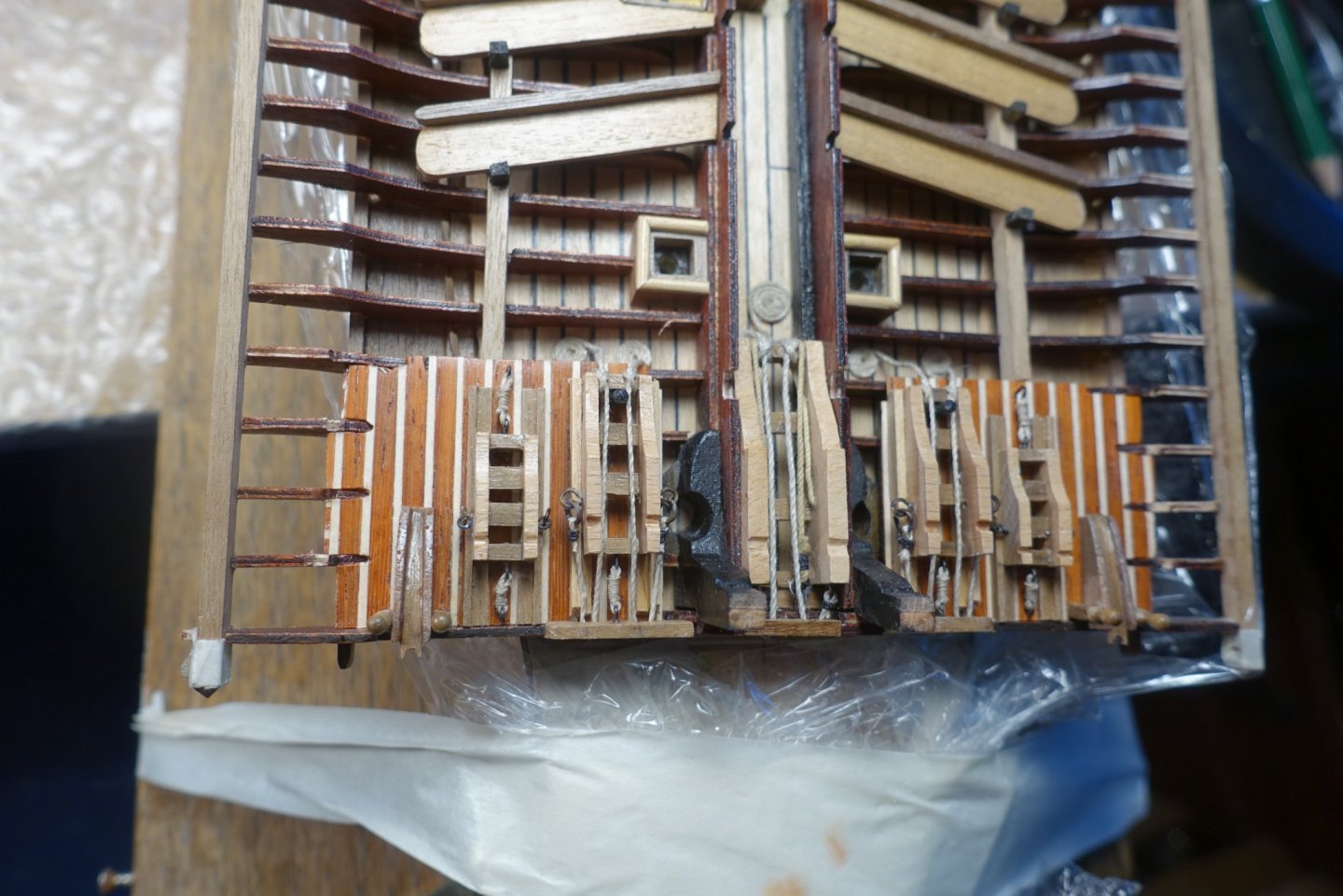
The outer platform is now glued. I had a discussion with Frank some time ago about the holes in the platform. He drew my attention to the fact that the shroud chains are led through the holes. Shroud chains contacting wood are probably not doing well on the long run. Thus, I simulated an enforcement of the holes. The outmost fixation of the outer platform is covered by a small brown/white strip 1mm thick and a walnut strip on the top. I put small “pyramids” on the stern and bow ends to cover the different types of wood. In the corel plans there is a suggestion to fix the blocks for slackening the fore lateen yard in the middle near the main cannon. This would not work since it would hinder managing the main cannon. Thus, I fixed it behind the main cannon.

- 112 replies
-
- 4
-
-
- corel
- reale de france
- (and 1 more)
-
When do you start with Coureur? I have noticed that you are currently working on other projects. Clark
-
Hi Udo, glad to see that everthing was o.k. Via CAF Ad, I also got notice of the kit which seems to be very sophisticated. However, I was a bit puzzled by the CAF Webite which looked a bit semiprofessional. Nevertheless, the coureur is on my list. I am eager to read your report and critics. Clark
-
You will enjoy it
-
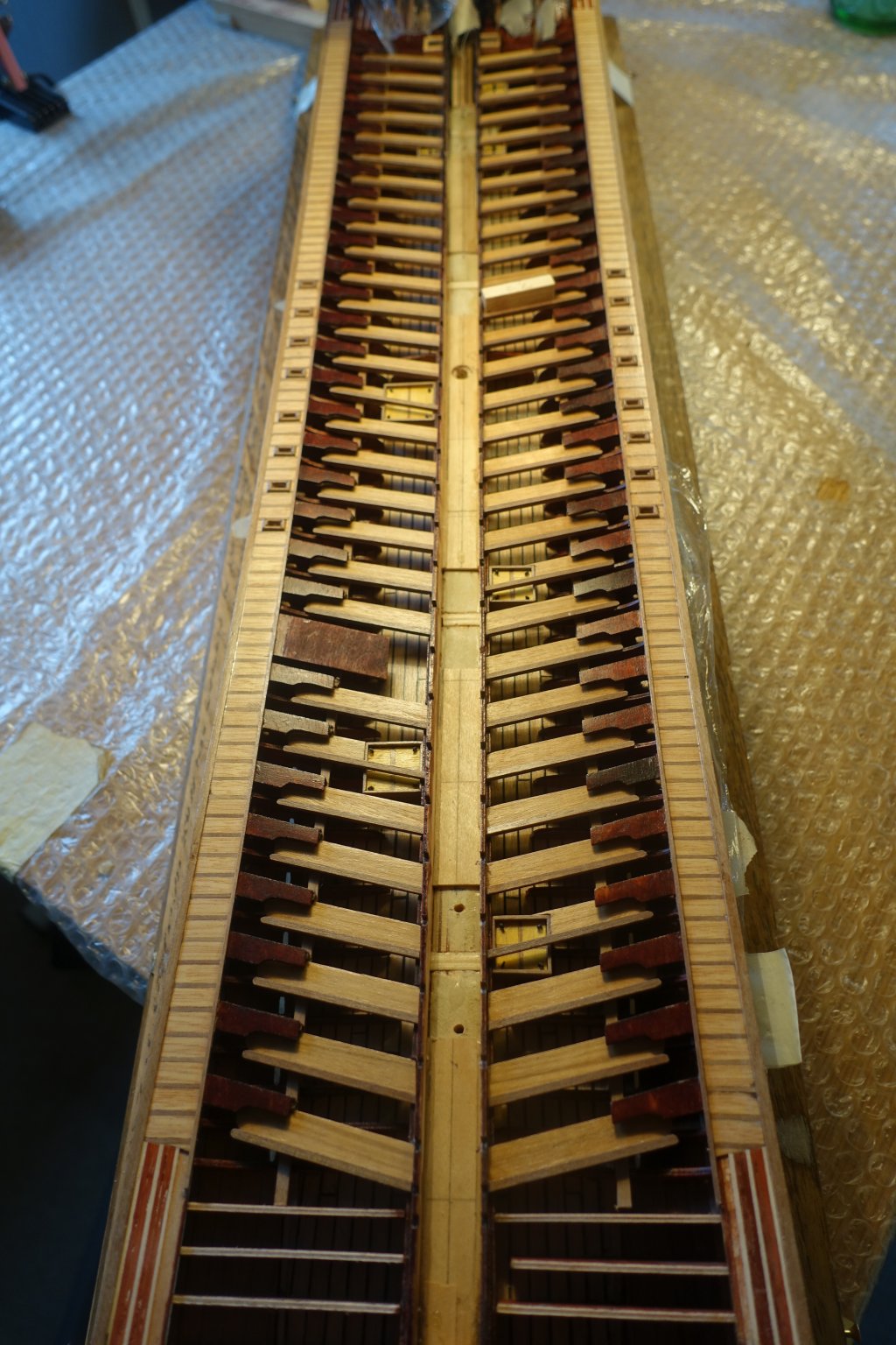
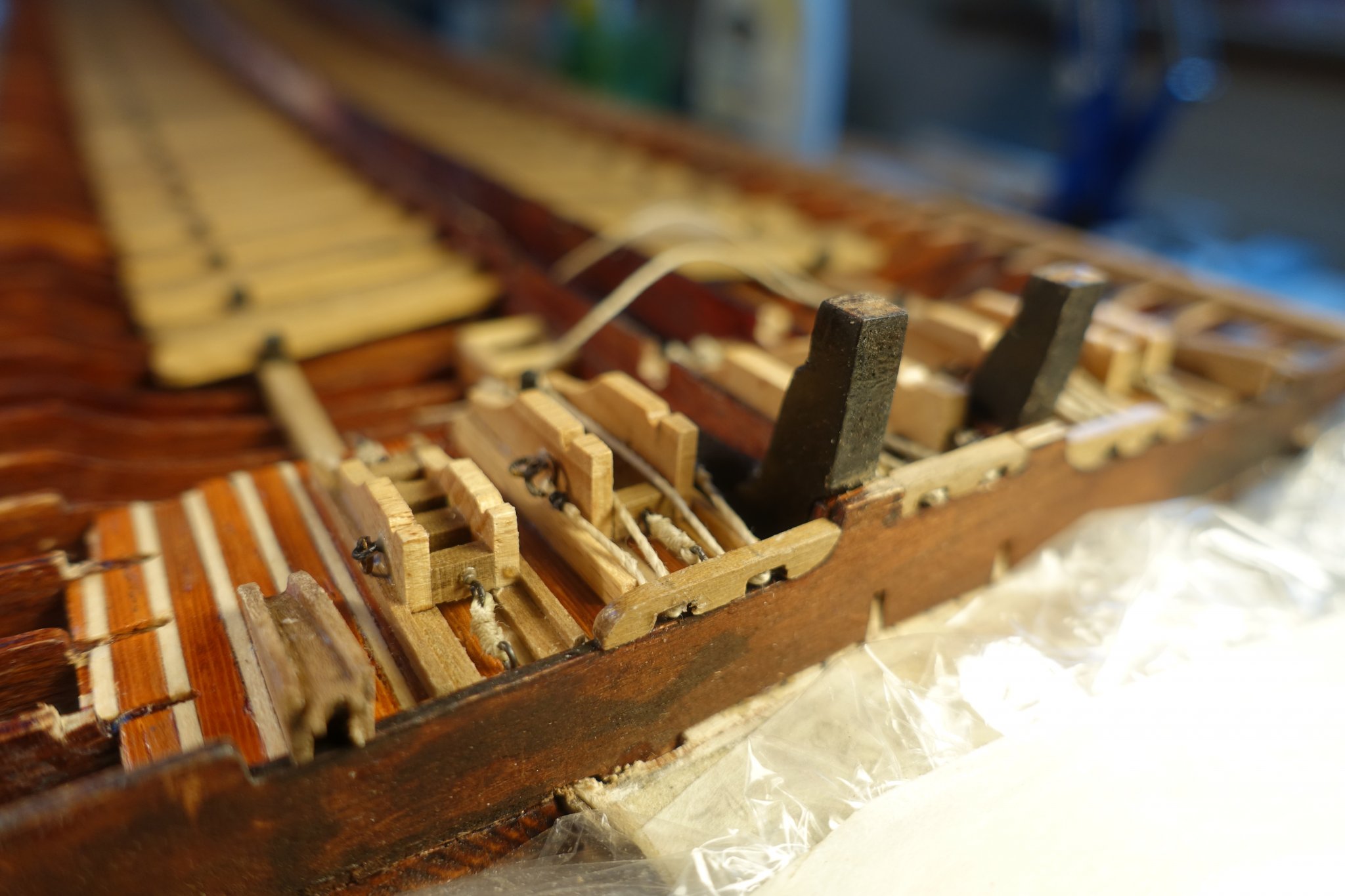
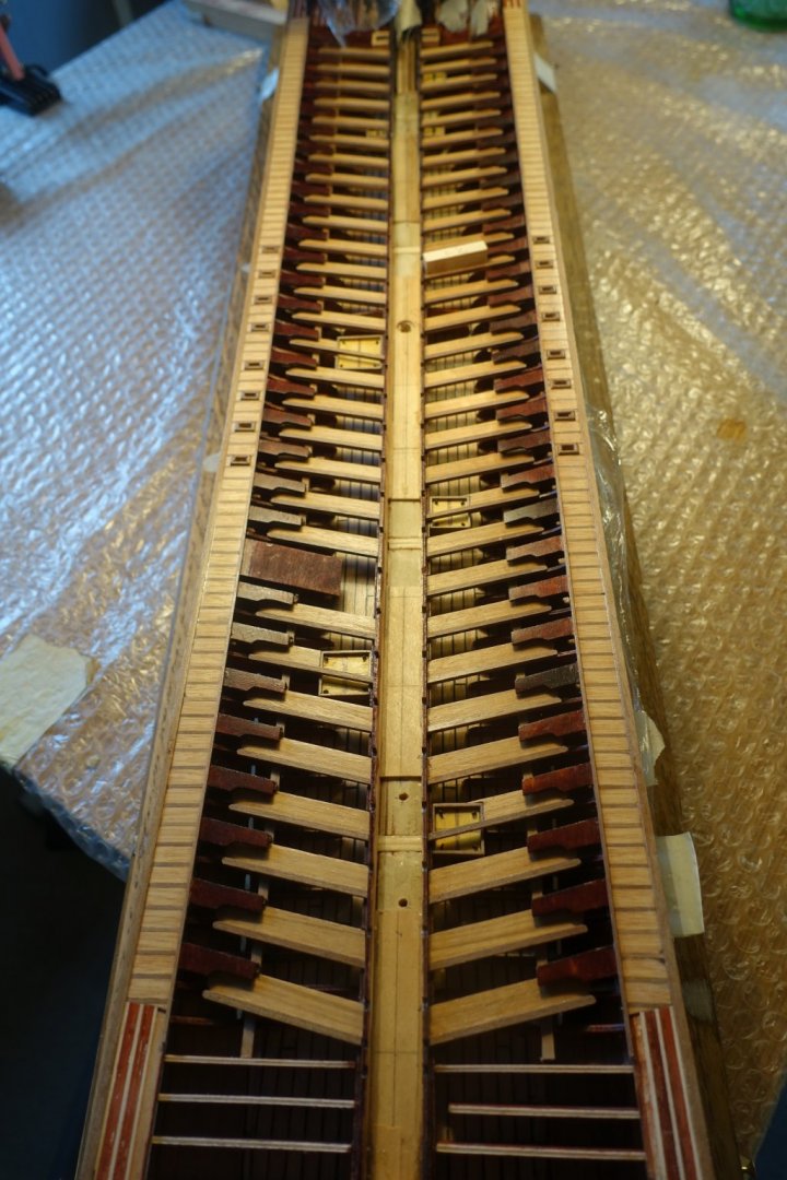
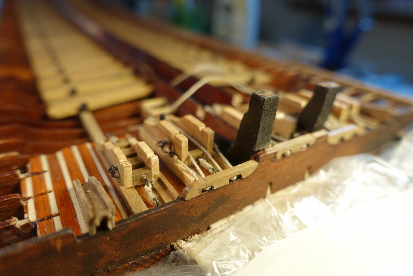
Regarding the gun deck, I had to regard some points. First, I want to show the ship on trip and not in battle. Thus, the carriages have to be tightly fixed and everything has to be cleaned up. Unfortunately, I could not find a plan how to fix the carriages. Frank (fmodair) shows one in his blog from the fleur de Lis but I am not sure if the fixation shown really worked when the ship was on trip. I created a solution of how I would fix them if I were the 1st officer or anybody else responsible.
- 112 replies
-
- 2
-
-
- corel
- reale de france
- (and 1 more)
-
Congrats. Did you even keep the music in mind (radio on the shelf?). Like Nils I am also wondering about heating, which might be a more severe problem in Germany despite climate change. Clark
-
Frank, looks great (as expected). Regarding the center decking planks: I have browsed through the plans and have noticed that some rigging runs through the midway. Thus I decided to make the center planks immediately before starting the rigging when all the other stuff is mounted. Do you have any idea how to handle the rigging, when the midway is coverd by planks? Clark
- 510 replies
-
- 1
-
-
- reale de france
- corel
- (and 1 more)
-
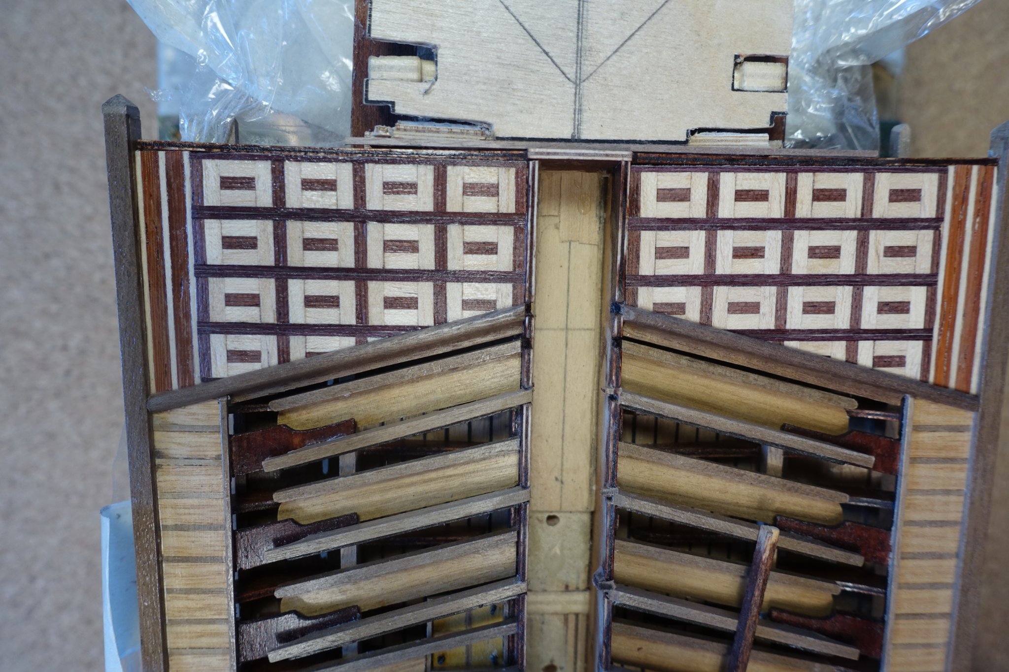
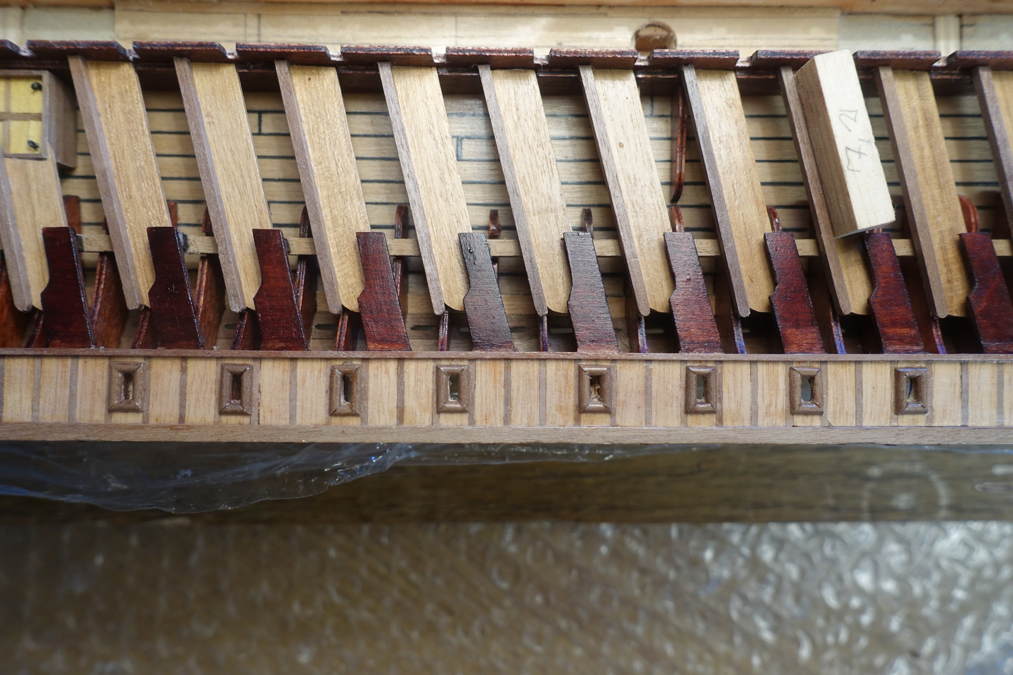
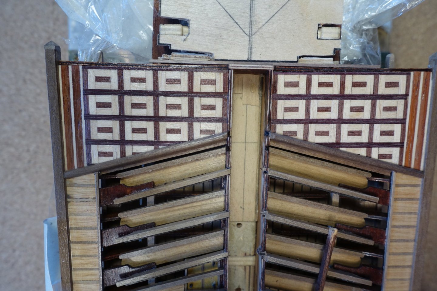
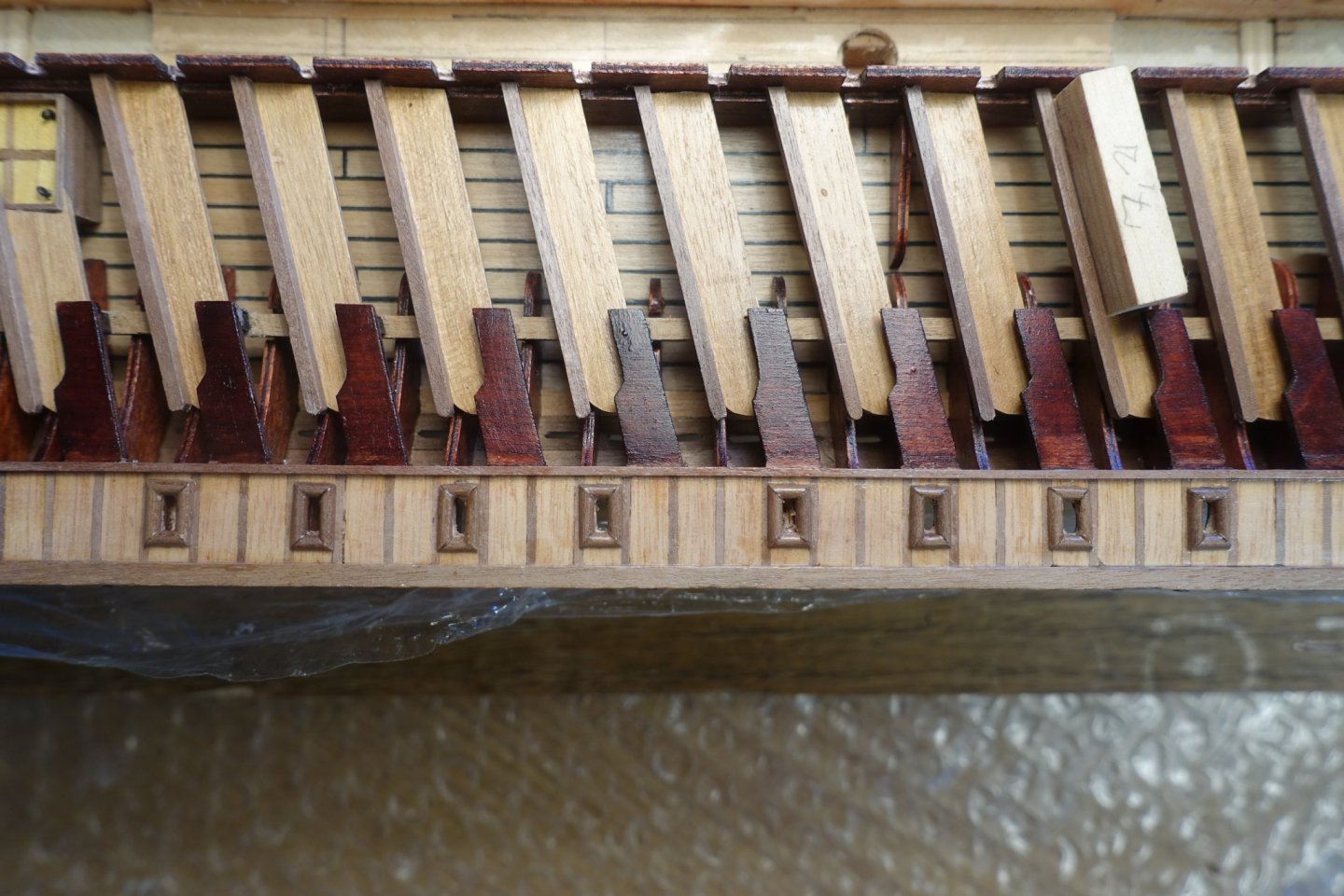
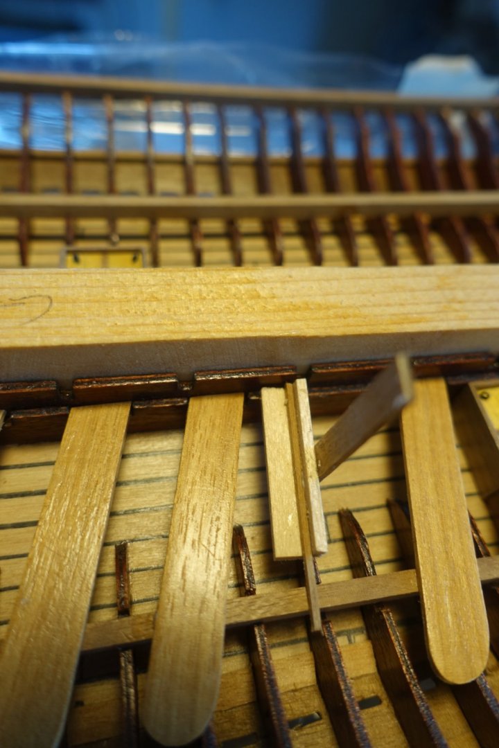
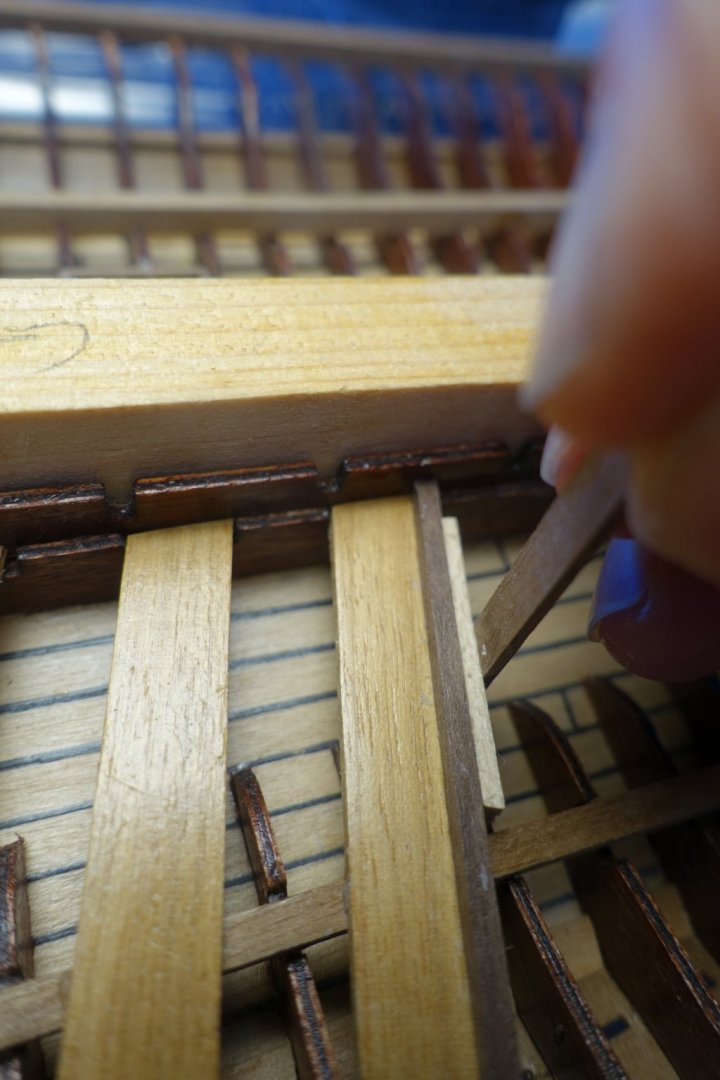
The footboards had to be glued overlapping on the benches. To get a 1mm overlapping, I made a small rectangle with 1 mm strip on it. Hope the pictures explains it.
- 112 replies
-
- 2
-
-
- corel
- reale de france
- (and 1 more)
-
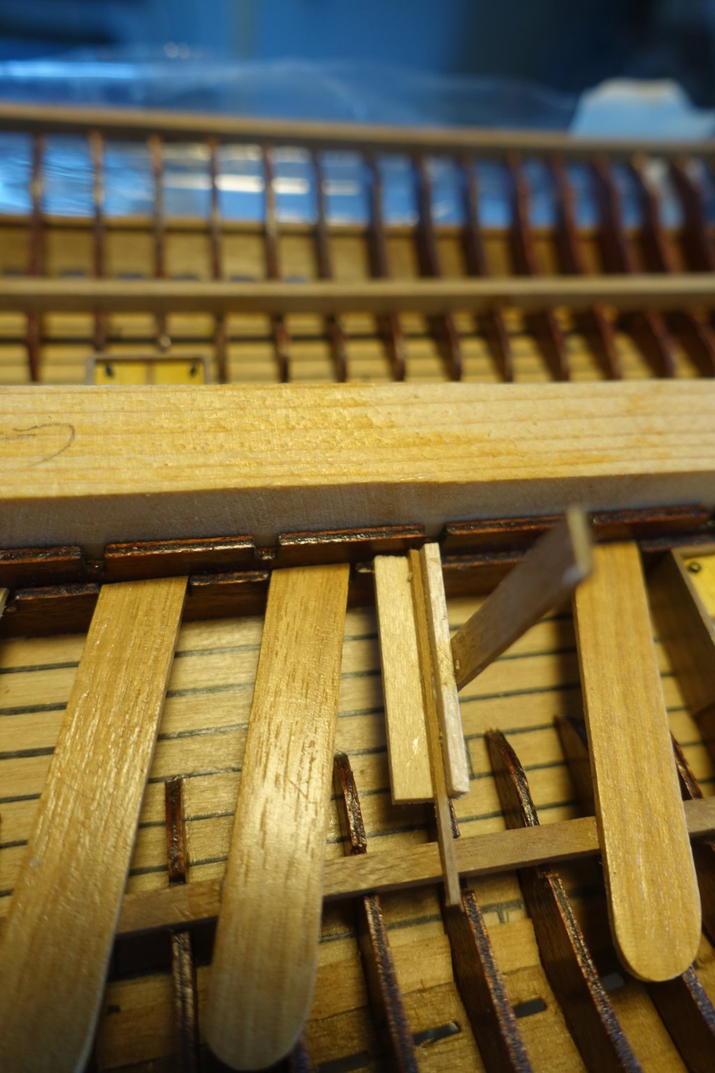
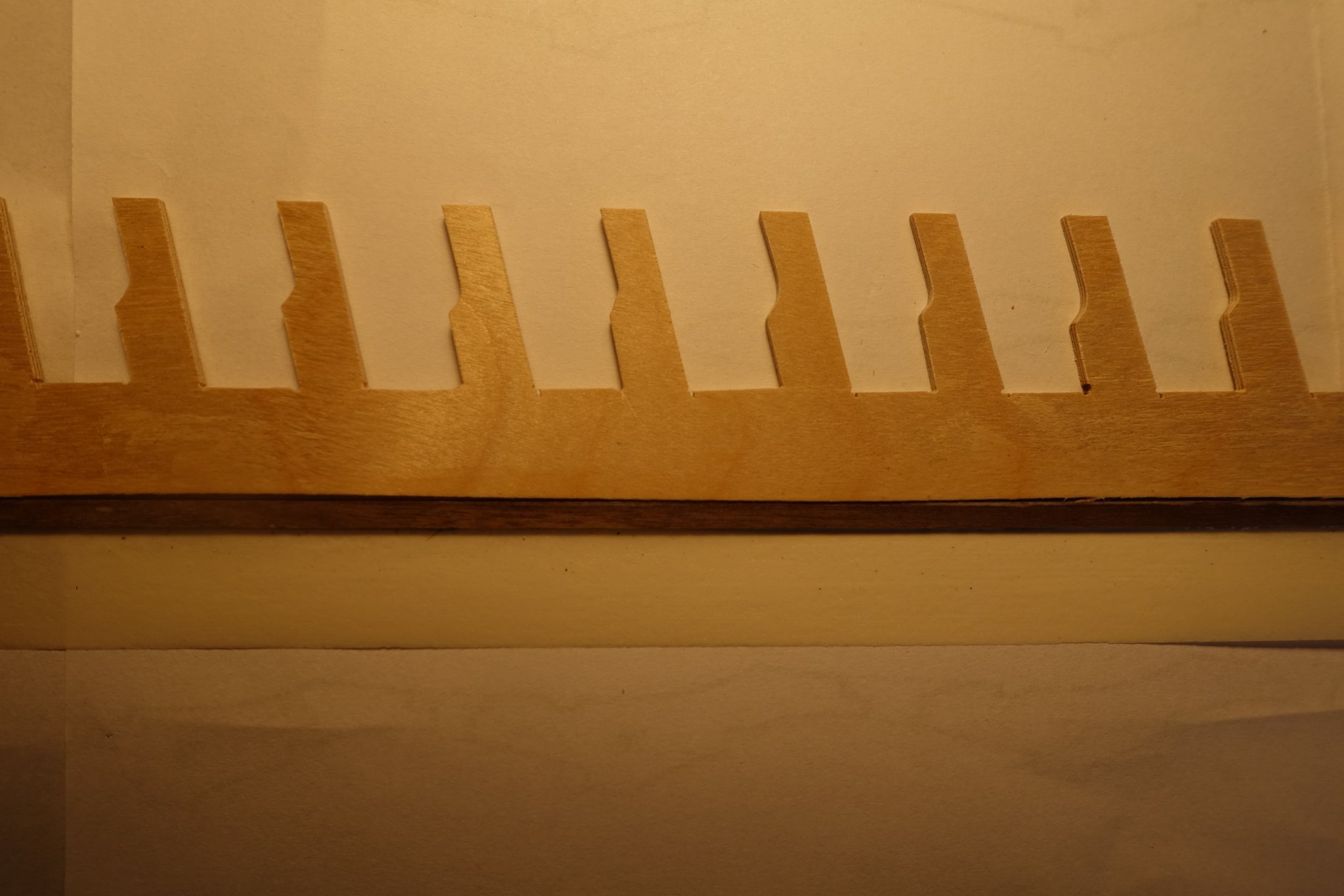
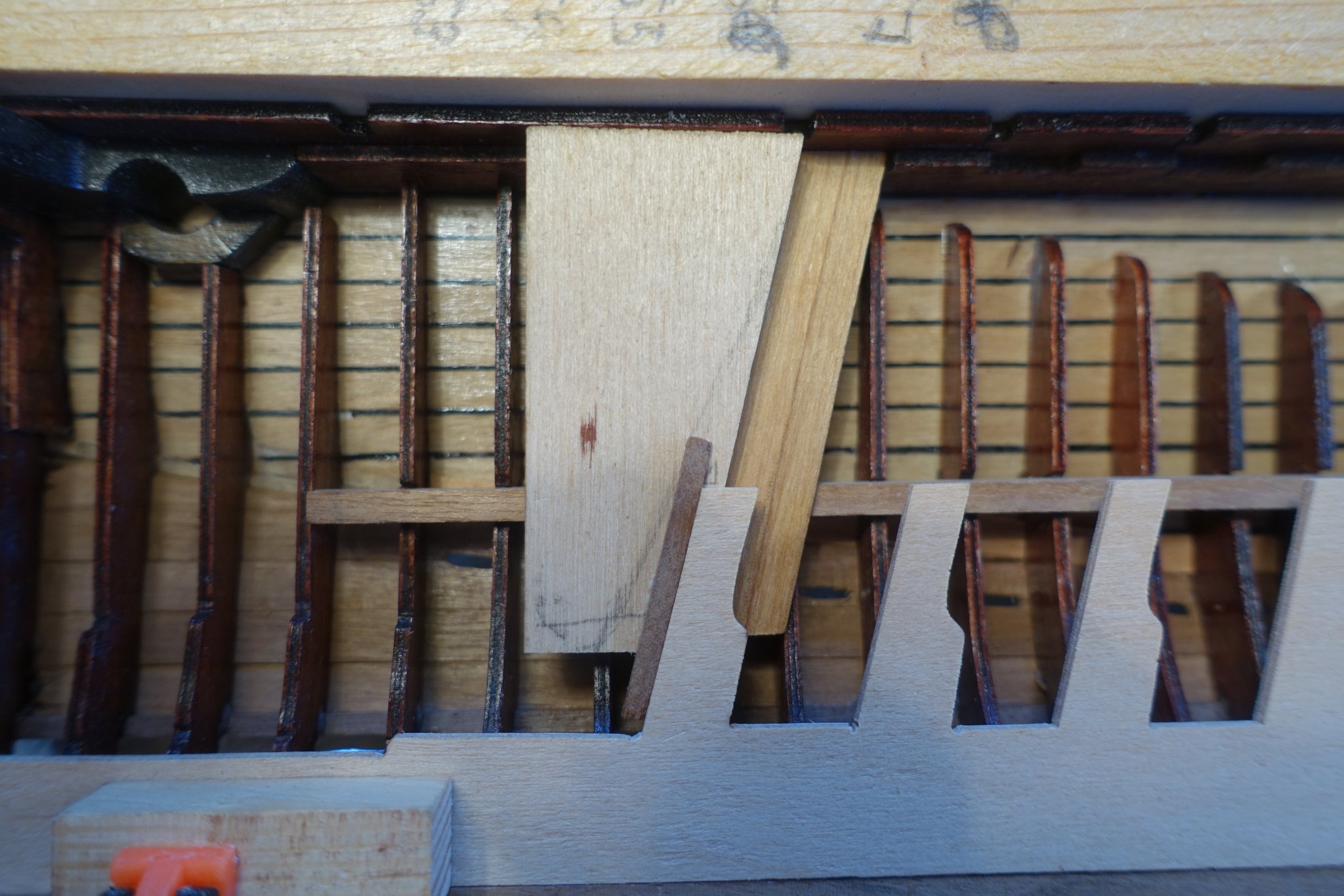
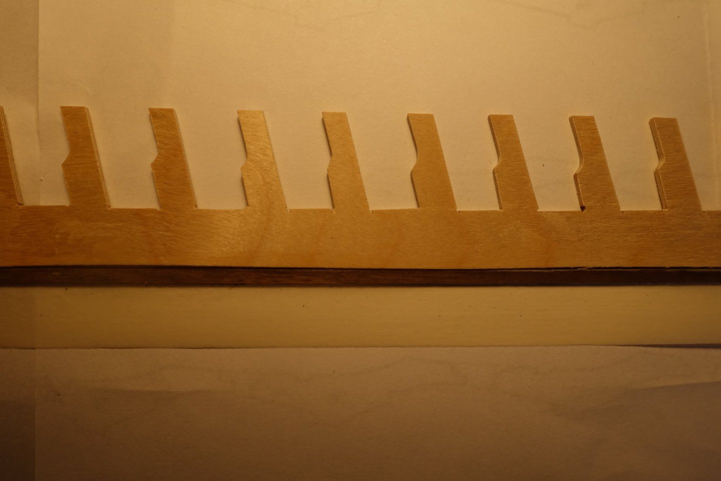
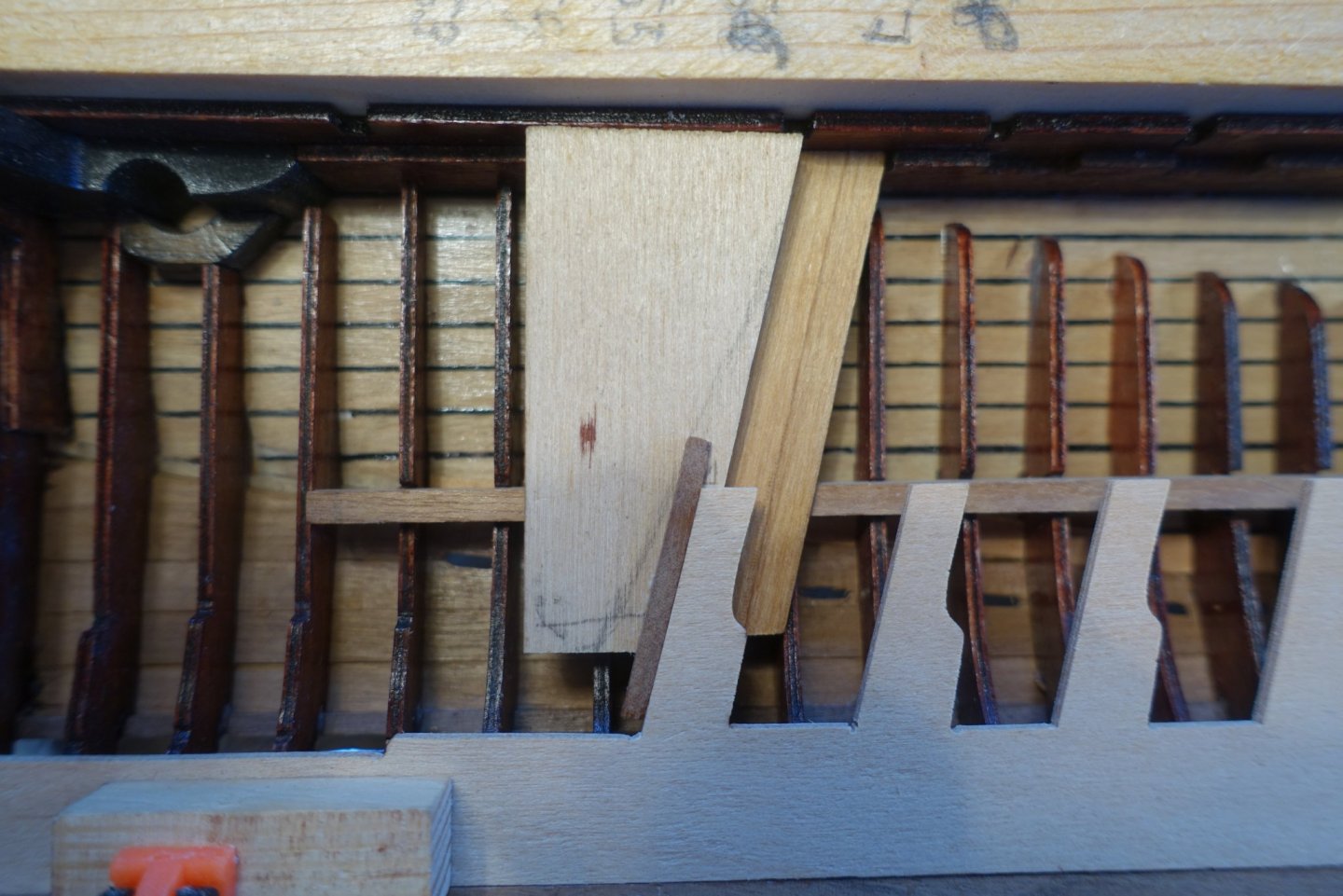
To arrange the benches, I wanted to use the template of the outer platform (named arbalester base by corel). However, the plywood pieces were very slovenly cut by corel. Thus I had to put some effort in sanding them or extending by gluing additional wood strips. May be it would have been much easier to make them new as Frank (fmodair) did. For arranging the benches in line with the outer platform I used a wood piece to keep the angle.
- 112 replies
-
- 2
-
-
- corel
- reale de france
- (and 1 more)