JSGerson
-
Posts
2,641 -
Joined
-
Last visited
Content Type
Profiles
Forums
Gallery
Events
Everything posted by JSGerson
-
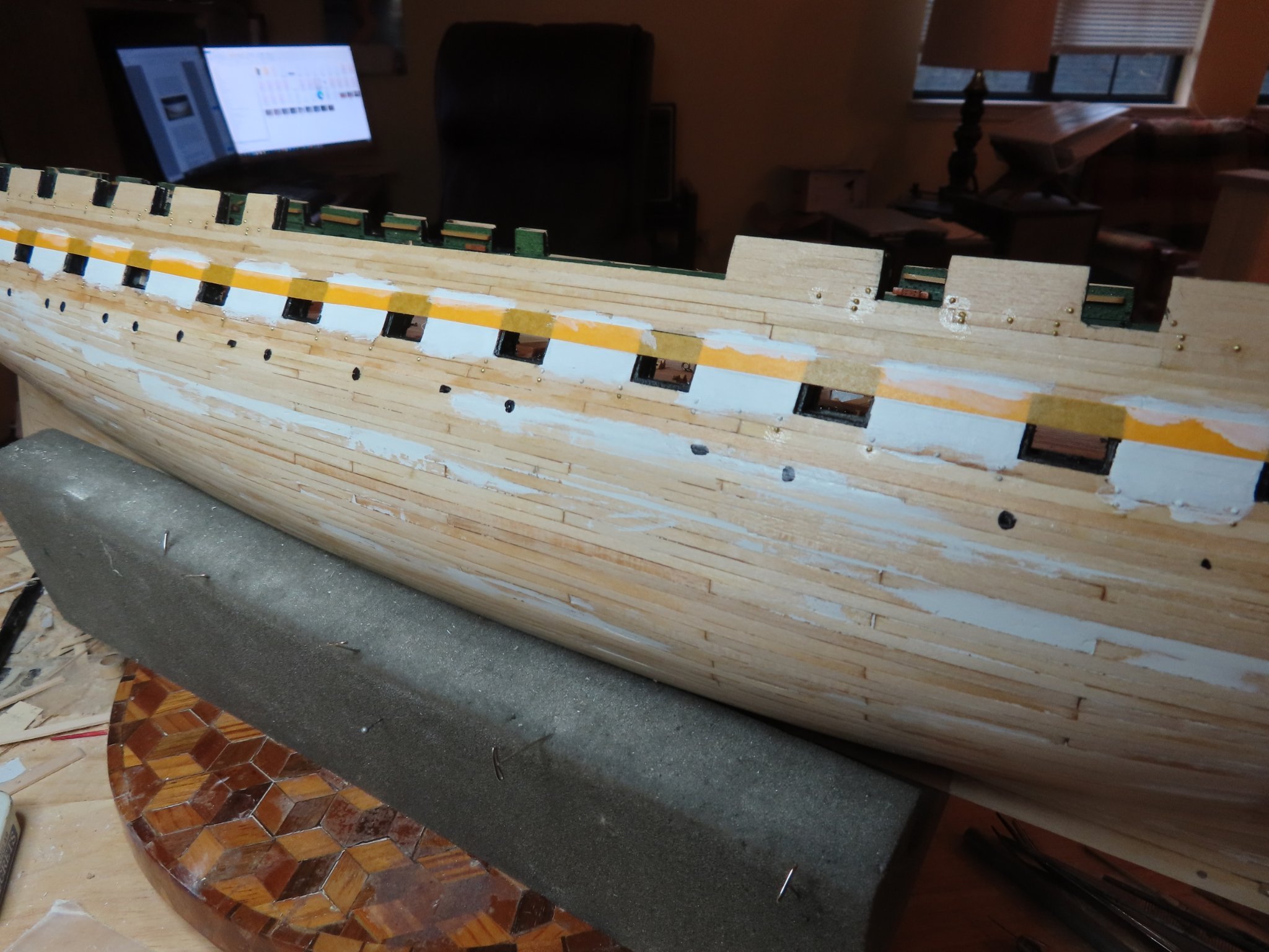
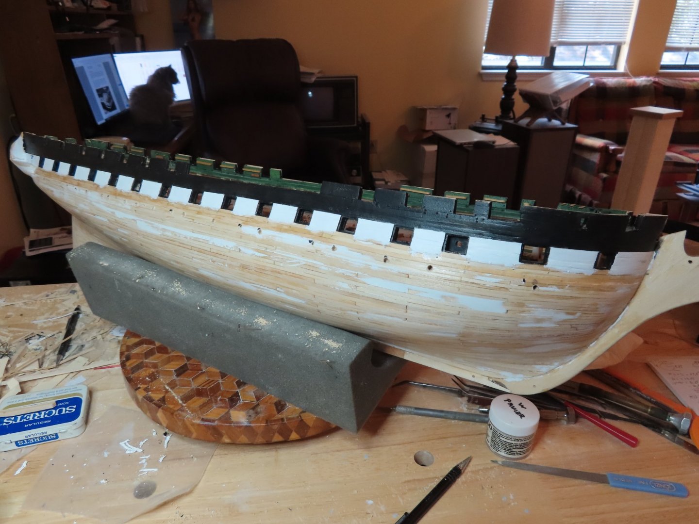
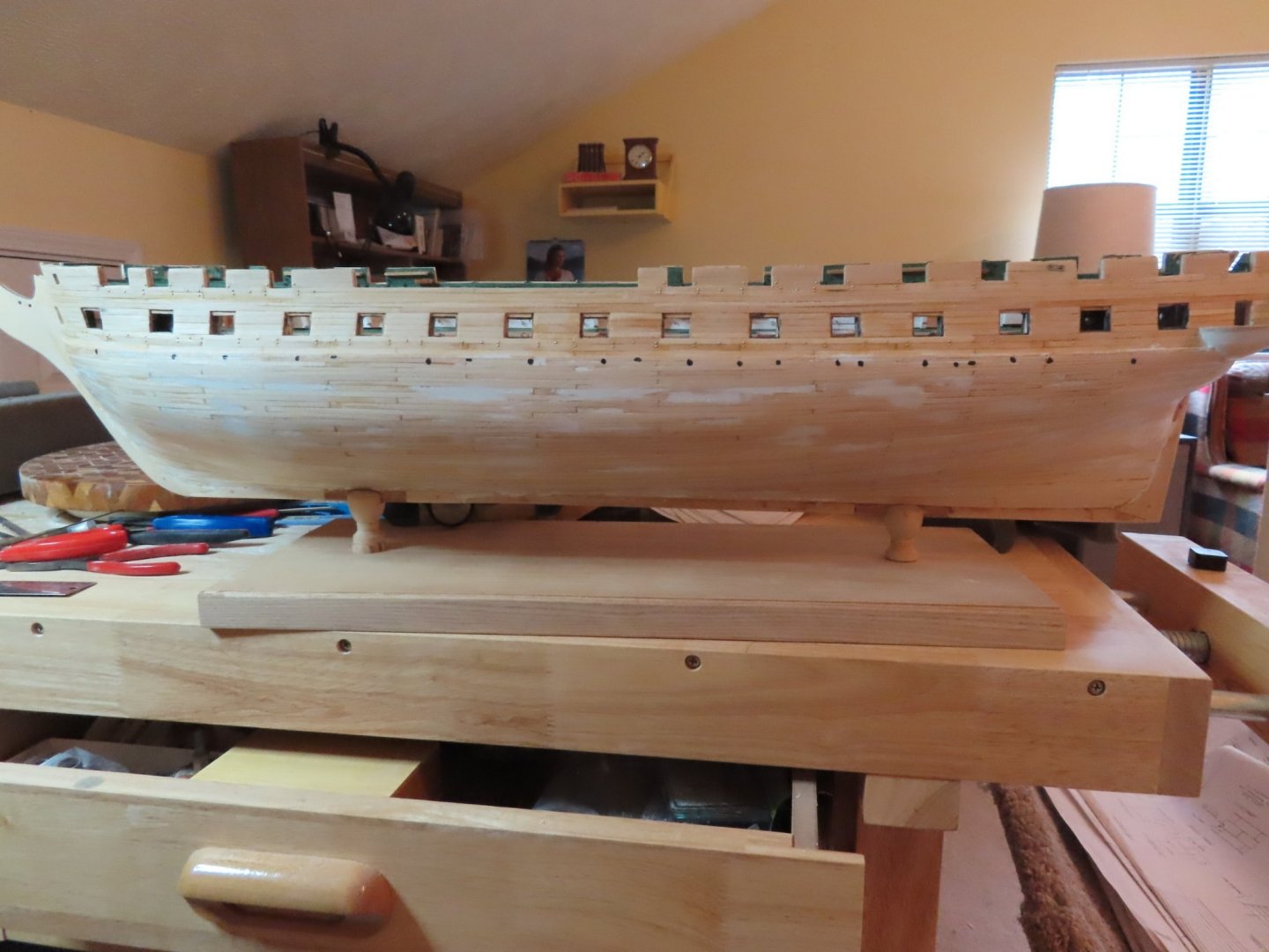
 ¼” wide auto pin striping tape was applied to the hull lining up exactly to the tops of the gun deck gun ports. A thin coat of white paint was applied along the top edge of the tape to seal off any potential bleed points. If there were any, it would bleed white on white. Then three coats of black paint were applied to the hull. Once the third coat dried to the touch, the tape was carefully peeled away. I have not done very much detail painting of this manner, so I had some minor touch-up work. Now for the interesting part, the quarter galleys.
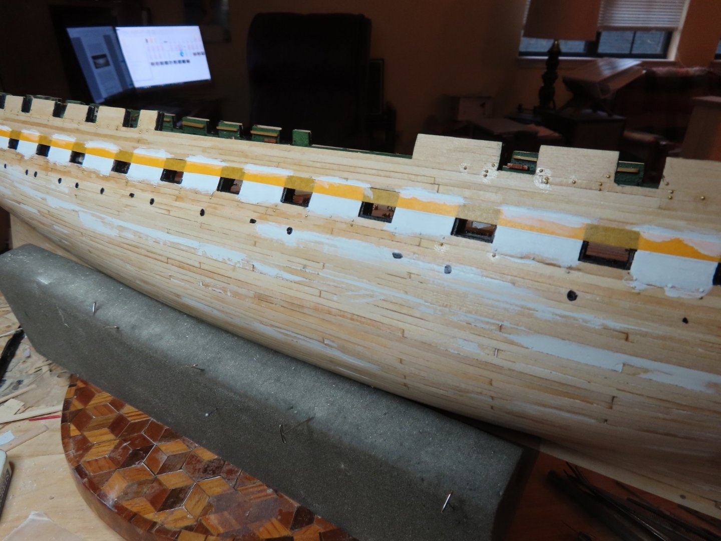

-
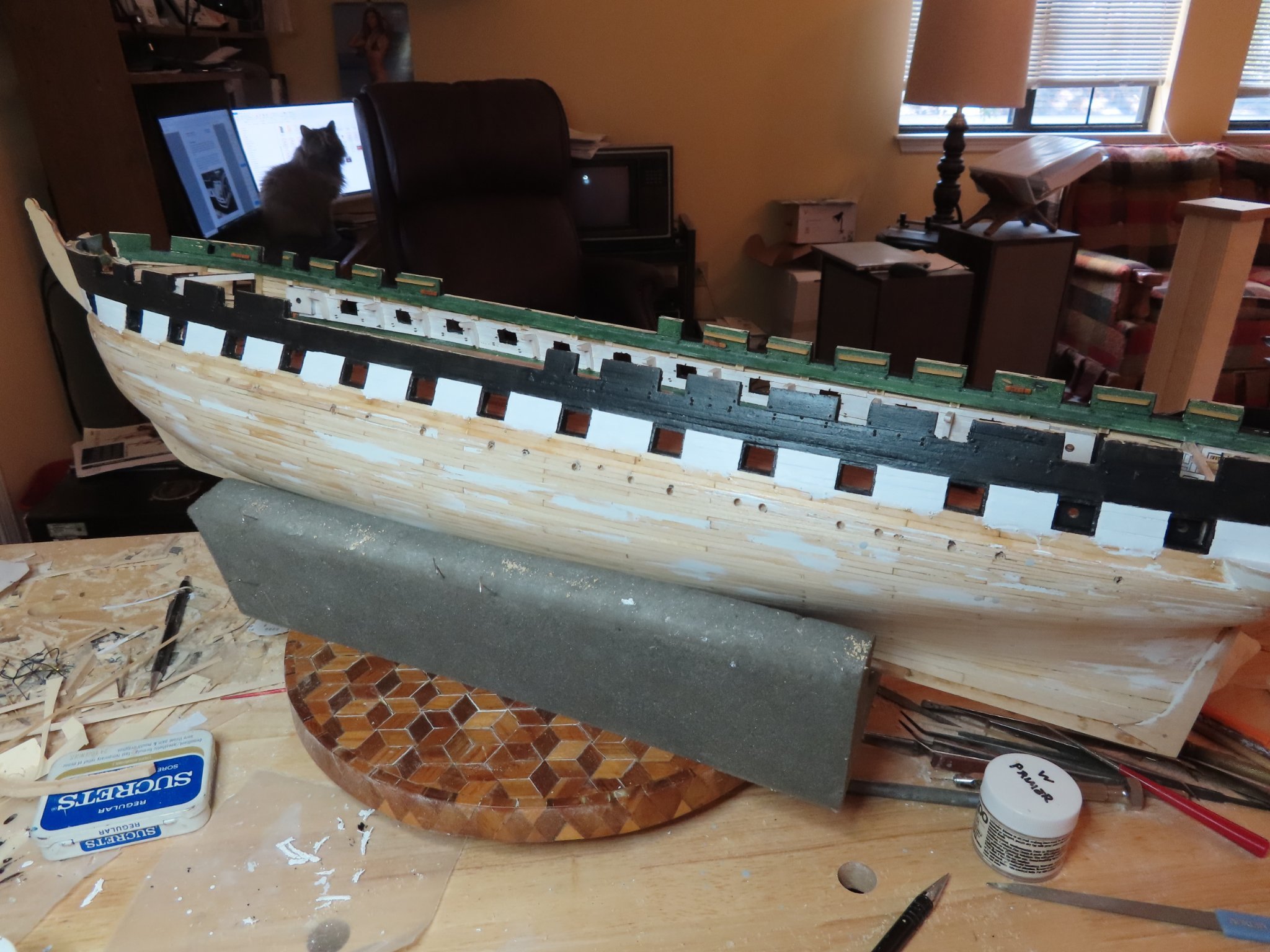
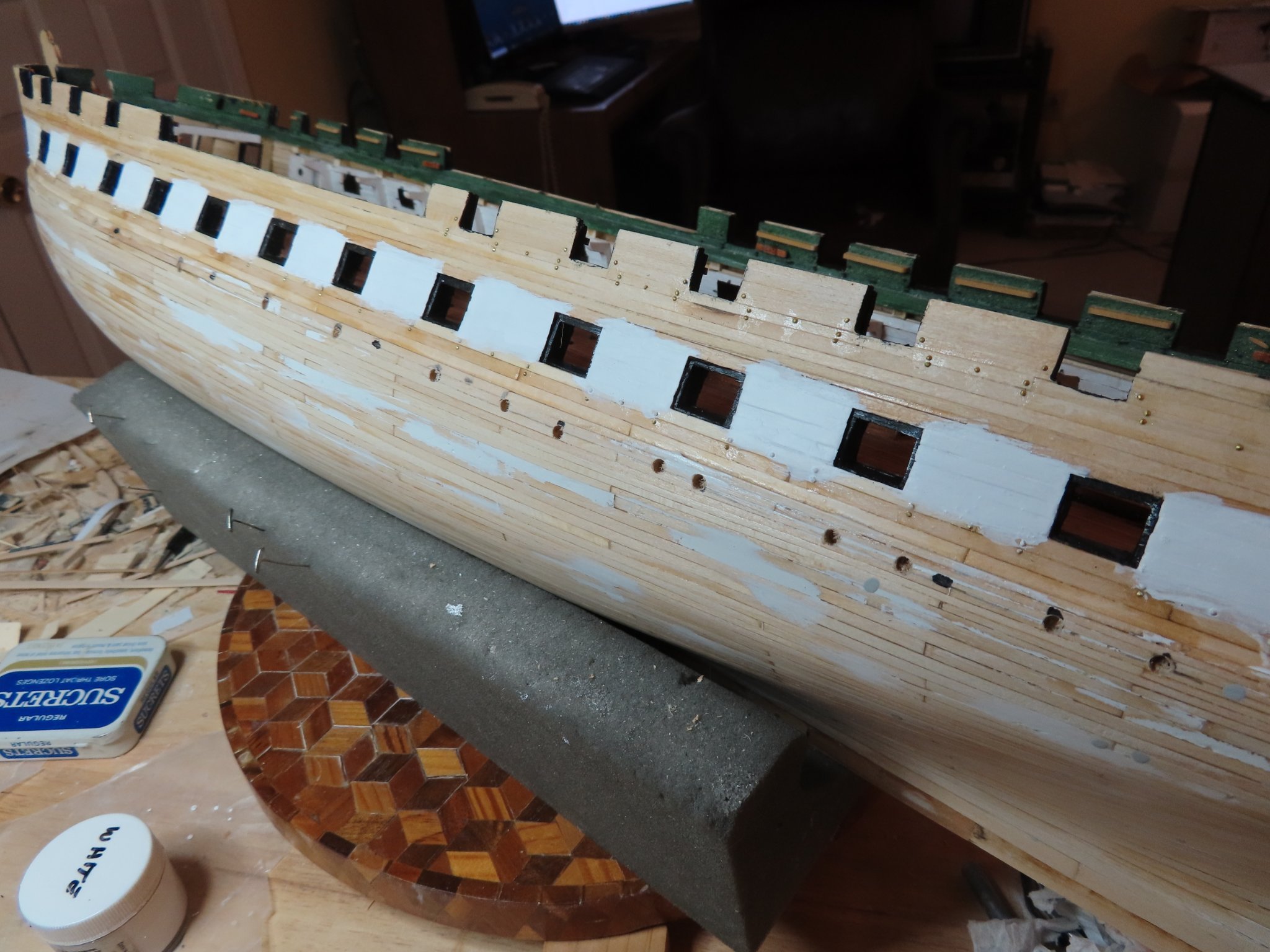
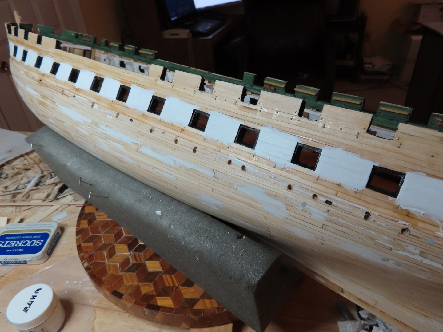
First step per the chapter is painting the interior frame walls of the gun ports black. The next step was to apply the white paint between the gun deck gun ports. I used a thin coat of white primer and then two coats of white paint, both supplied by the paint supplement package offered by Model Expo. The instructions specifically indicated to over paint the white areas between the gun deck gun ports to ensure full white paint coverage. The black paint to follow is supposed to cover the excess.
-
Change of Plan – Painting the Upper Hull While waiting for my drill bits to arrive, I decided to look ahead at the infamous quarter galleys that has been the bane of so many builders by reading Robert Hunt’s practicum’s Chapter 7, “Outer Hull Details.” I realized then that I was once more in sync with the practicum …for the most part. Among other things, the practicum directs the builder to install the port lights and scuppers after the quarter galleys are constructed. Once the quarter galleys are done, the hull details port lights, scuppers, the stem and transom decorations installation are next. All that work will free up any restrictions to competing the gun deck interior which has a lot of work. Based on that thought process, I’m postponing the port light and scupper installation and will proceed to following Chapter 7. Since I have already marked the port lights and scuttle locations, I went ahead and drilled pilot holes with the new drill bits, so their locations wouldn’t be lost when this portion of the hull is painted black and covers up my position marks.
-
Very nicely done. I know the Byrne's saw is a thing of beauty, but didn't know it could cut those small pieces with such s large toothed blade. Anything that delicate, I always switch to my finest tooth blade. Maybe it's because you got the sliding table attachment? I don't have that one. Jon
-
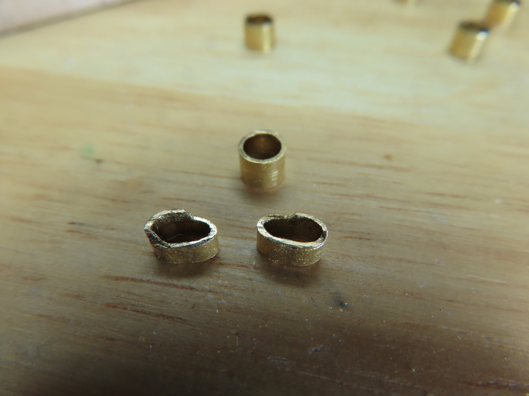
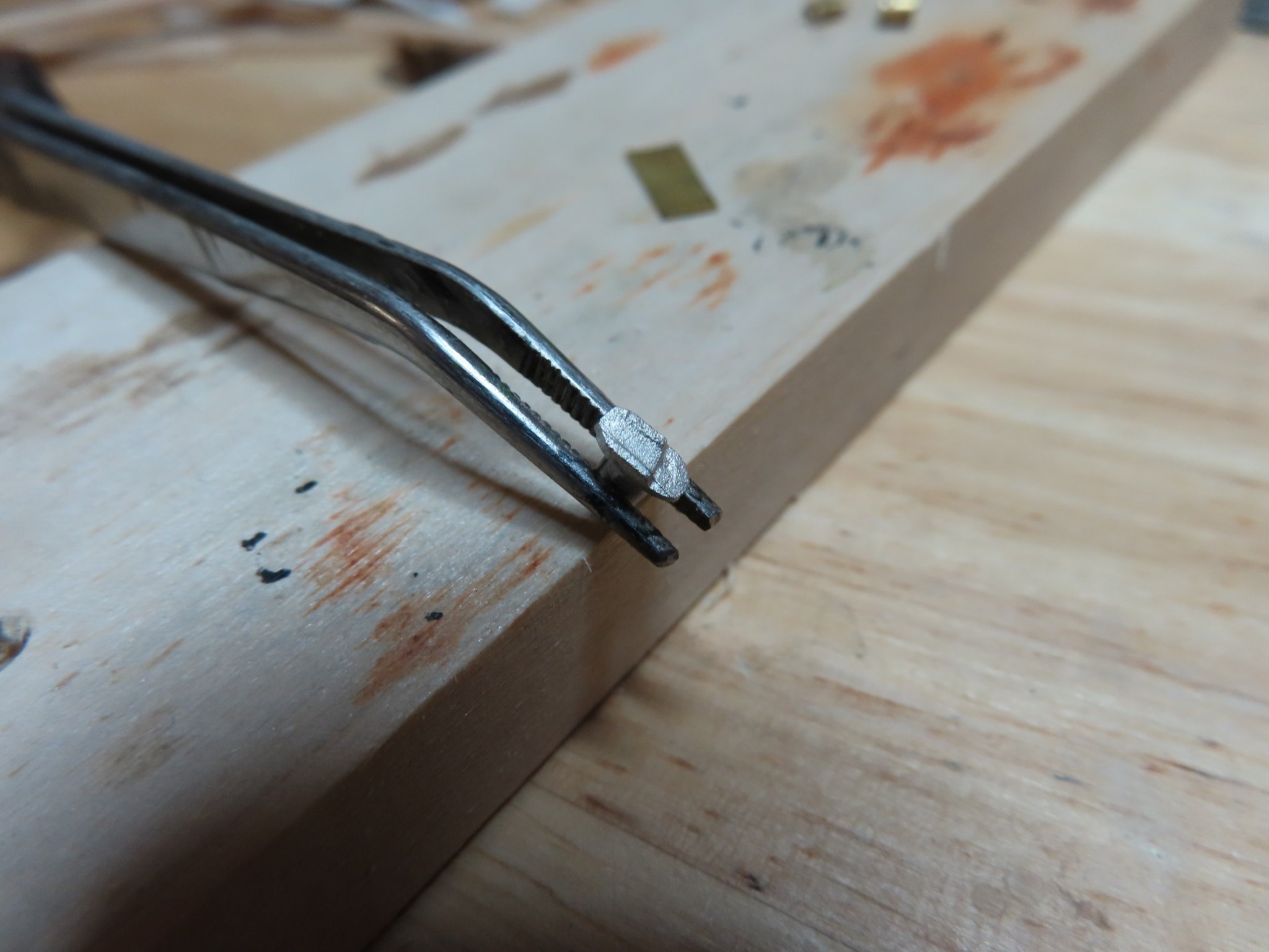
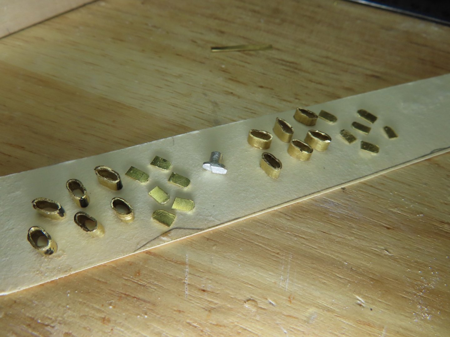
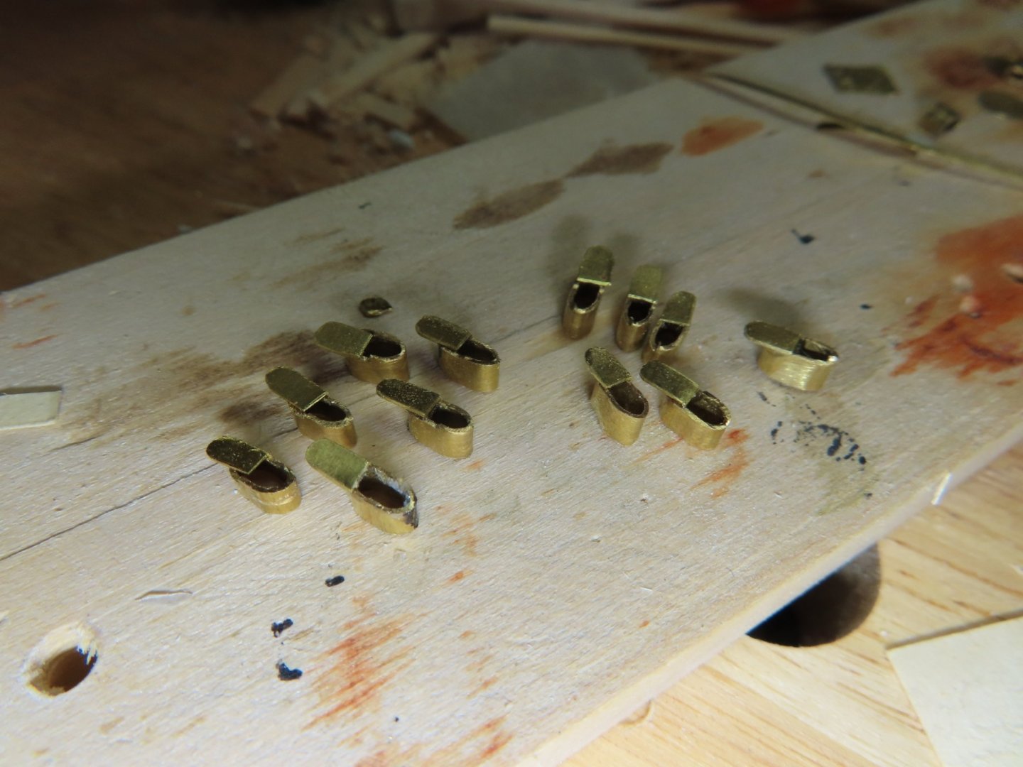
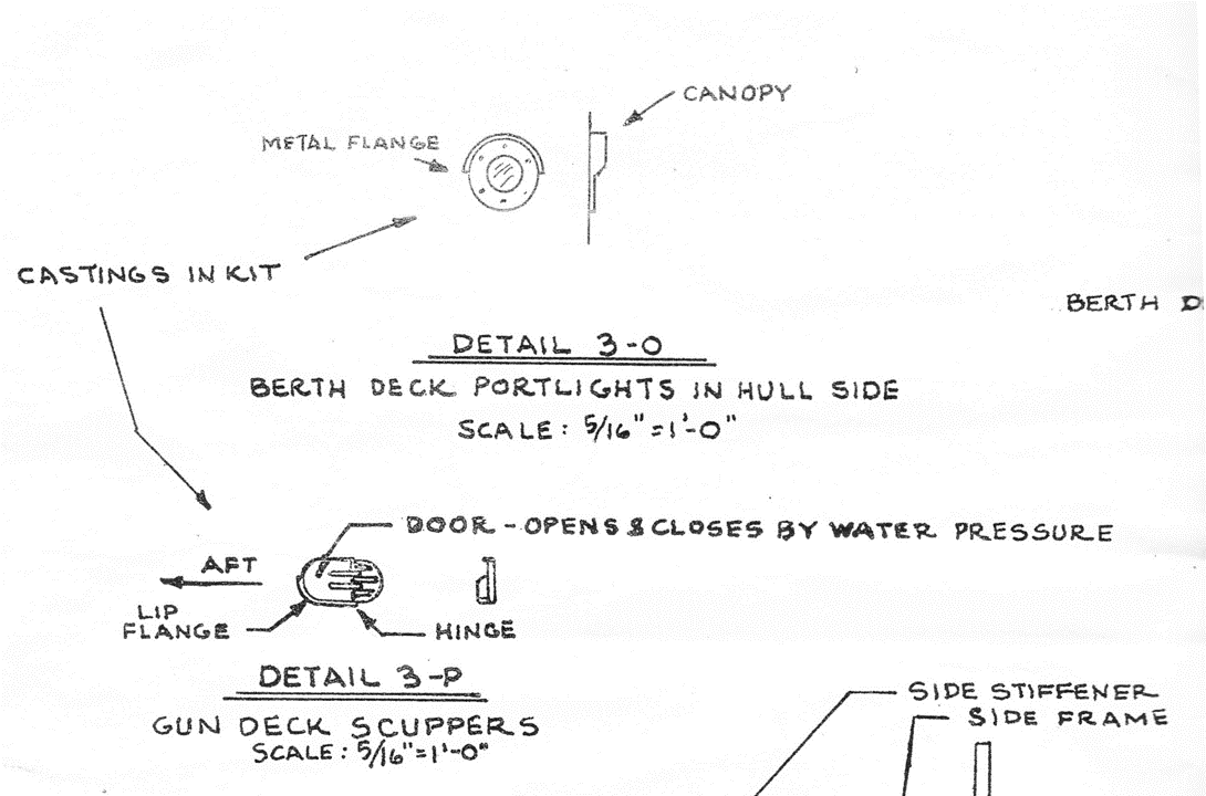
Using a 5/32” dia. brass tube (chosen by trial and error), short pieces are cut off and squeezed just enough to create an 0.0960” oblong cross section tube. A piece 0.010” sheet brass, was cut into a rectangle with one end rounded to represent the scuttle door. Filing the edge of the formed tube leaving the corner edge proud creates the lip flange. In order to drill a couple of holes to create the oblong shape, requires a 7/64” ( 0.1094”) bit. Another drill bit I needed (I actual purchased a set of 16 bits) The door was attached with CA glue. These will be inserted into the wide hole in the hull almost flush leaving the door and flange lip protruding from the hull. This will provide some detail even when painted black.
-
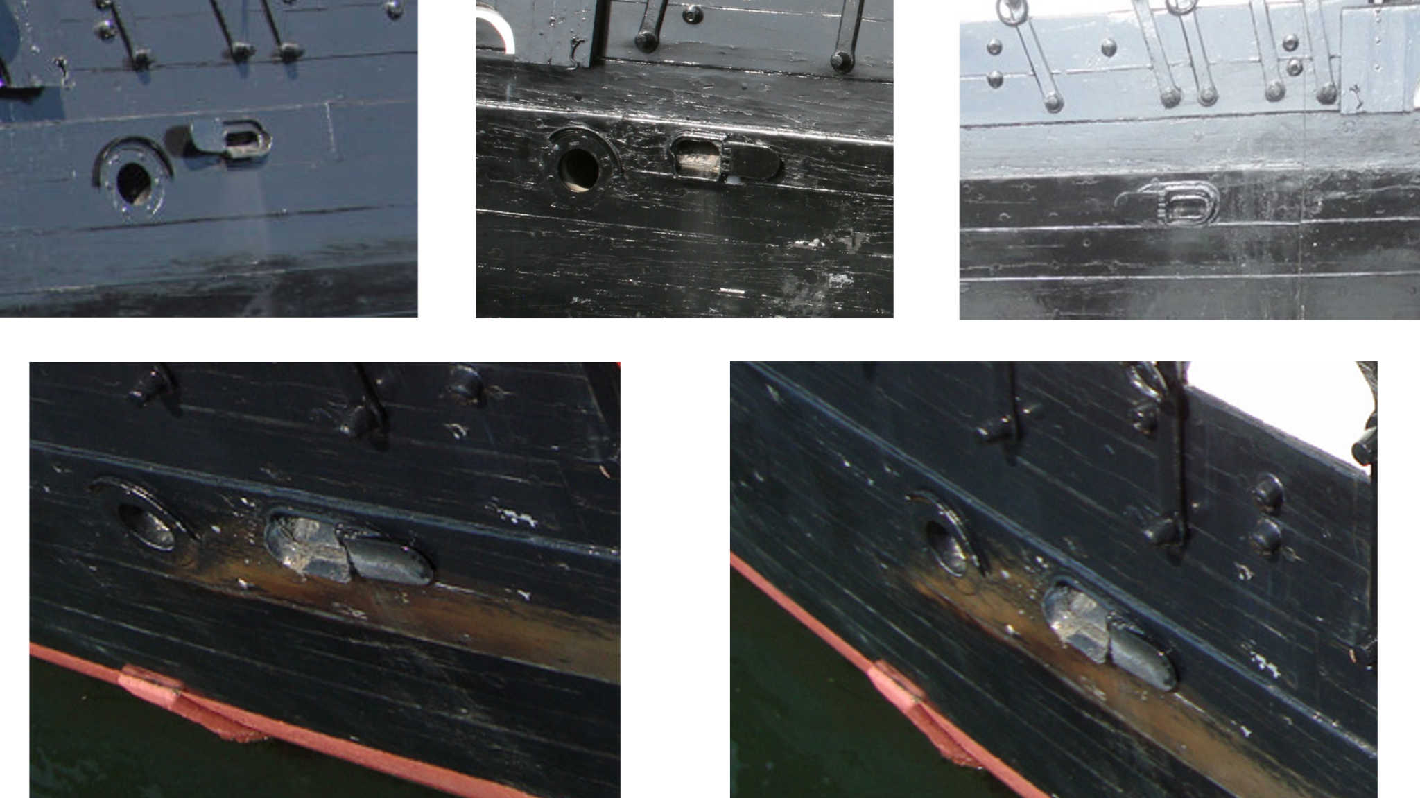
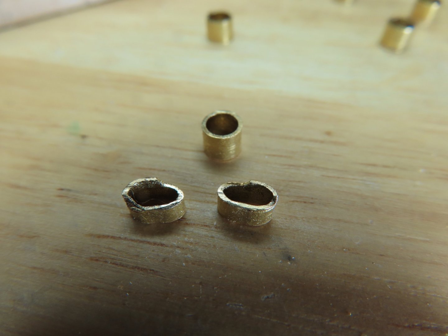
In short, on the actual ship, the scuppers are wide open whereas the kit plan and castings have them closed. At first, I thought the casting were misshapen due to their small size and I would have to make them from scratch. The kit plan states the scuppers are opened and closed by water pressure, so I suspect on the real ship, they are being held open somehow for some reason. This explains the casting’s appearance. Looking at the casting more closely, you may notice that there are two crude lip flanges. The actual lip is always on the bottom aft end of the scupper. By filing off one of them, the casting can be properly installed on the appropriate side of the ship. But this really moot because if I were to install them as is and eventually paint them black like the hull, you might as well as not install them at all; you can’t see anything to identify them as a scupper. So being a glutton for punishment, I decided to make them from scratch and show them open.

-
However, it was a different story with the scuppers.


-
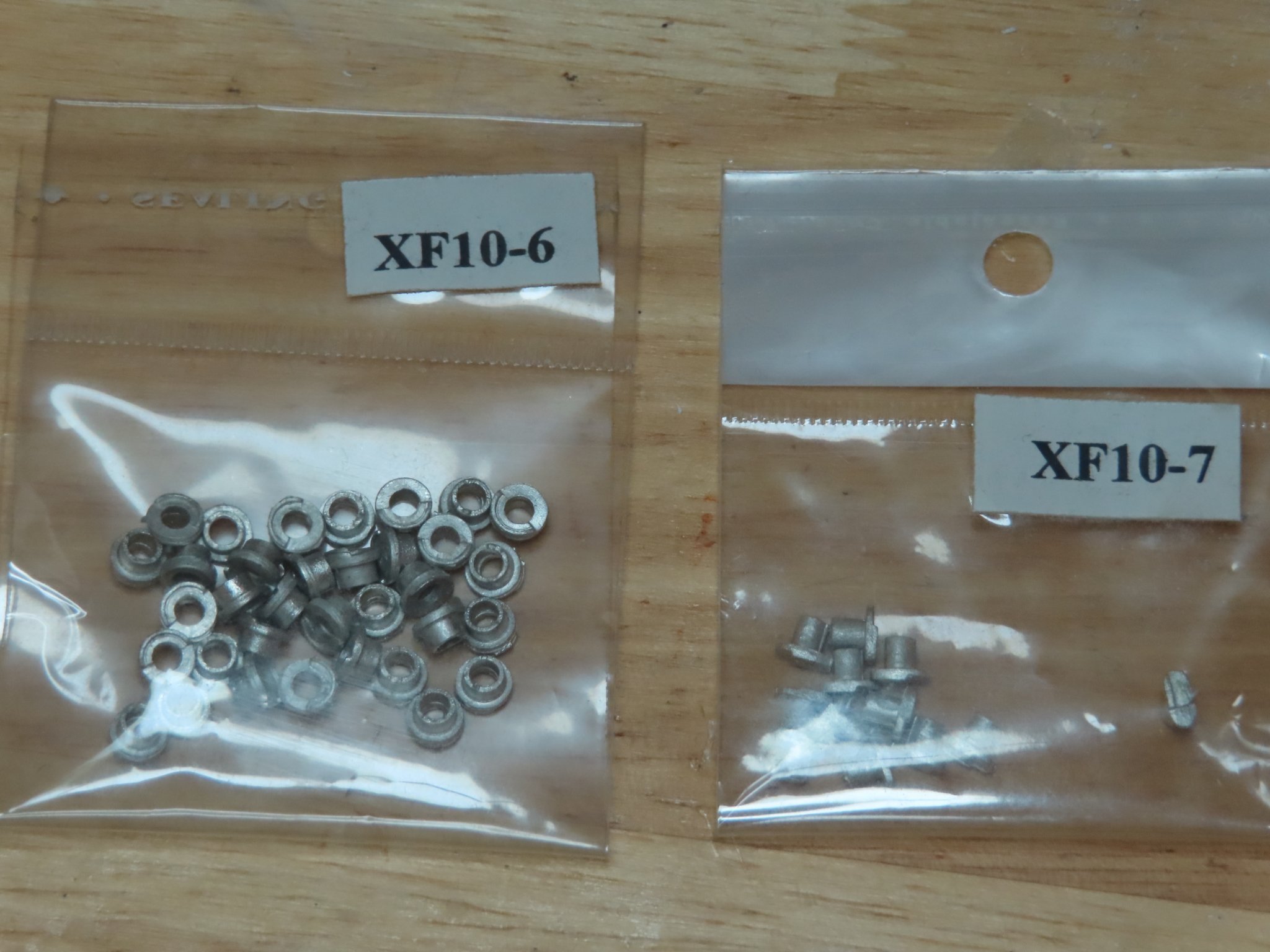
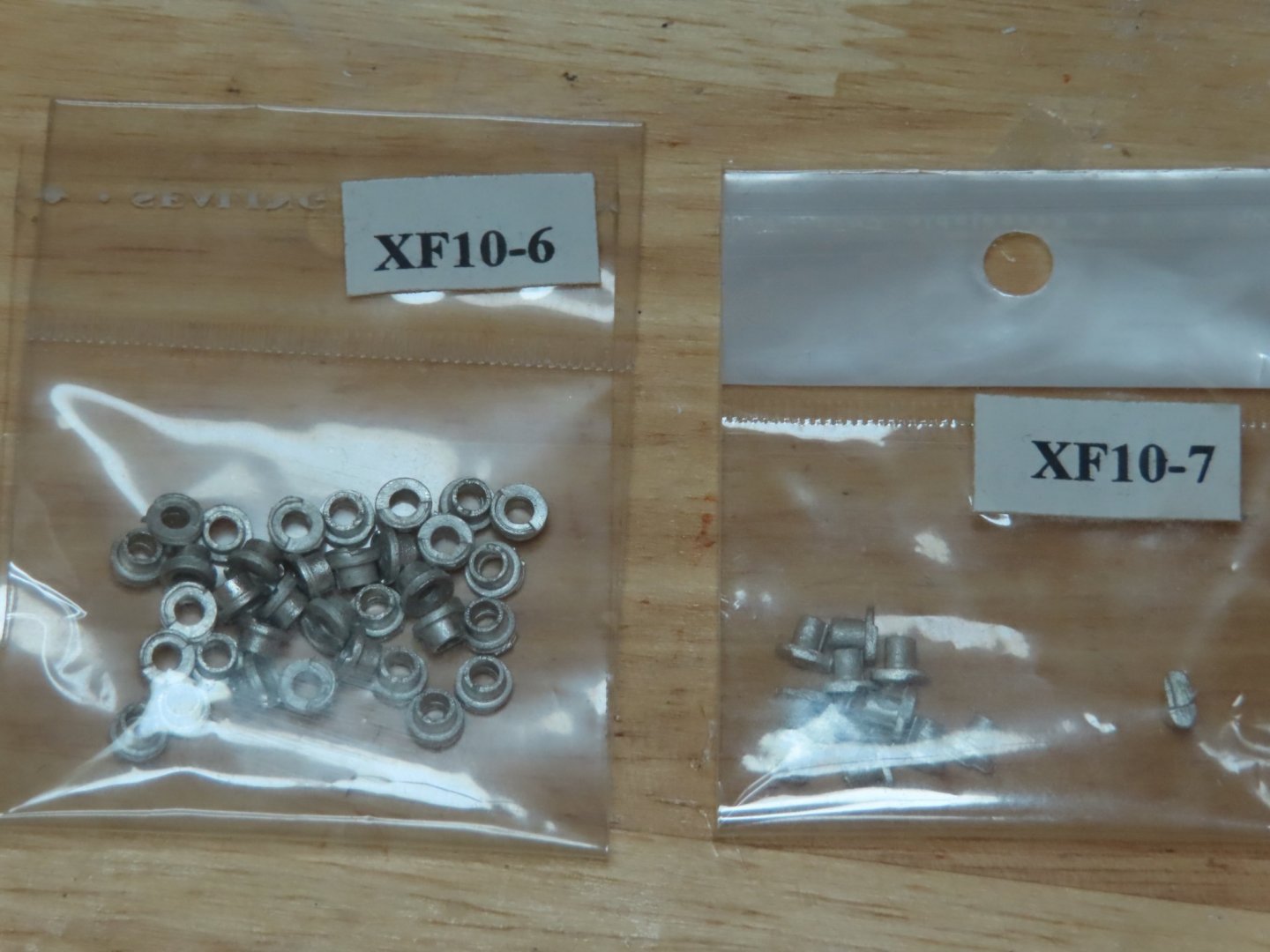
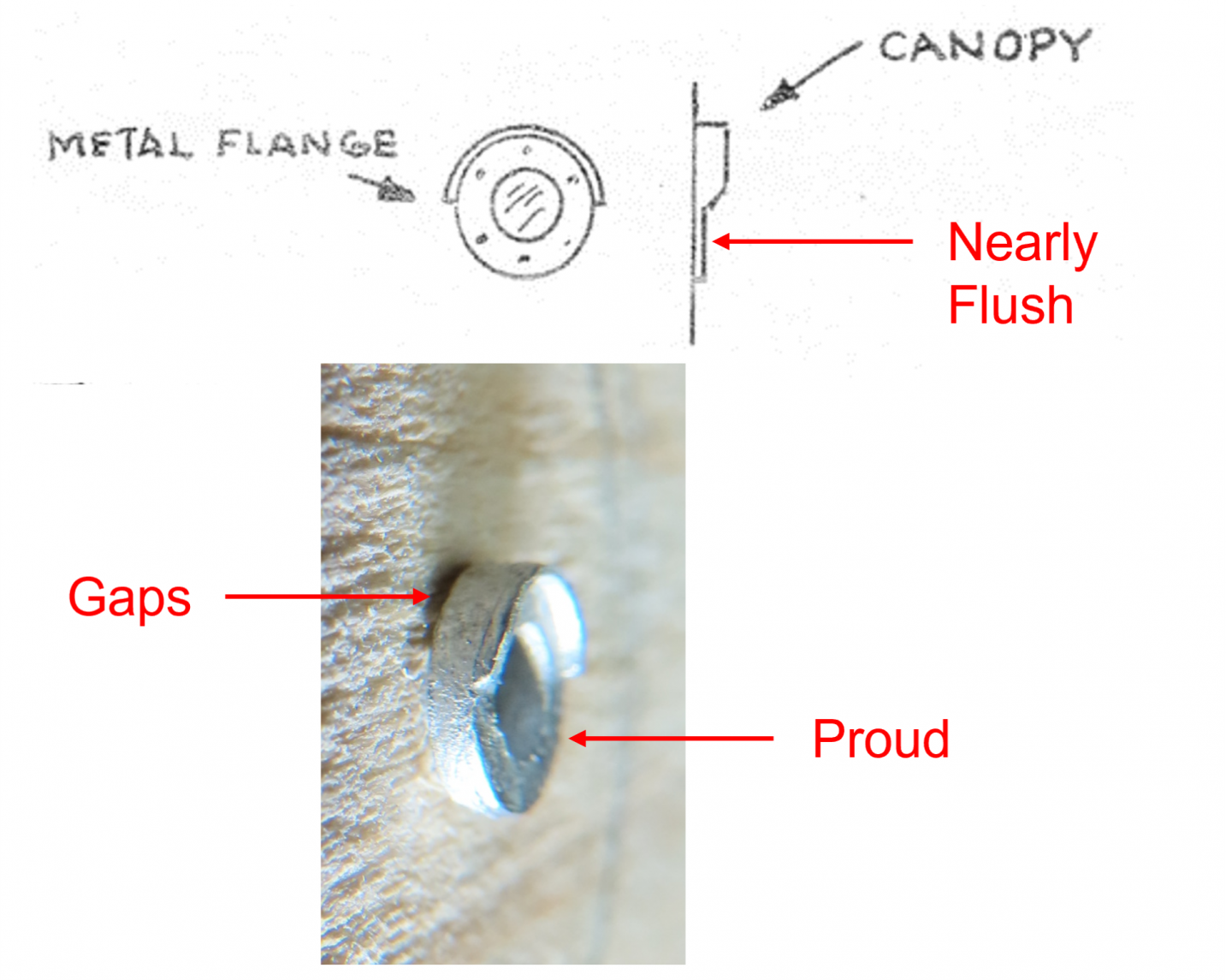
Looking at the portlight castings, they looked straight forward enough, although based on the photographs and the kit plans, they have to be set almost flush to the hull and not proud if inserted into the hull using the just casting tenon. Additionally, when I made a test installation in a block of scrap wood, the casting also tended to leave a gap between the casting and the hull. That meant drilling into the hull twice, once for the casting tenon and a much shallower larger diameter countersink for the outer diameter of the port light to set into. By my measurements, the tenon is about 0.1385” dia. it varies a bit on the casting, (a little larger than a 1/8” (0.1250”) drill bit and little less than a 9/64” (0.1406”) bit. The full diameter of the port light is 0.1825”, just shy of a 3/16” (0.1875”) bit. Ideally, I would use the 9/64” and 3/16” bits to drill the holes, but I could not locally buy a 9/64” bit and had to order online. The order is due in a week. In the meantime, I cleaned off the tiny imperfections from the casting process.
-
Berth Deck Portlights and Scuppers Next, I thought I would install the berth deck portlights and scuppers castings; something nice and simple…Ha!.
-
I was surprised to see you paint over all of the cleats and other hardware. Did you want them green?
-
Jeff, I haven’t reached the point where the I’m installing things like the trim and decorations yet. If you’ve been following my build log, you may have observed that I like the little details. So, I haven’t read or planned for those yet, but I noticed the very nice eagle on the stern of your model. How did you apply the colors to the eagle’s shield? Does the practicum provide the process? If I were to do it today without any outside instruction, my first attempt would be to make a decal using my inkjet printer. I can’t tell from the photographs, but did you make the stern stars or were they provided in the kit? I should know what’s in the kit, but I concentrate on one thing at a time and constantly have to refresh myself when I move on to a new task. The coppering concerns you raised is something I must contend with as well, obviously. I’ve been thinking about this for a long time. I looked at models built before the last restoration and noticed a majority of them did the copper nailing wrong, They made the coppering look like boiler plate rivets with oversized “rivet” bumps proud of the copper surface. Looking at the images of the restoration, it was obvious there should be fine dimples into the surface of the copper, which I may add is a long and tedious process. Some builders used a fine ponce wheel on the plate edges only, others a pressure stamp with multiple needle points for the whole plate. I plan on doing a few trial processes to figure out what I’ll do. One thing is clear to me though, there will be copper plates and not just copper paint on the hull. Jon
-
Robert (Bob) Hunt runs the lauckstreetshipyard.com website. He has has written many practicums which help the novice builder immensely. However, they are not cheap when they are not on sale. My first one was for the Rattlesnake which I used religiously. I could not have built that model without it. I am using my second one for my Conny more as a guide in specific areas. I gain a lot of knowledge from the build logs of dozens of members of this website, picking and choosing methods suitable to my skills. Still, as an overall step by step guide, I rely on Bob's practicum. I hope this helps Jon I noticed Gregory's response which was posted just before mine. Yes, Bob can be cranky, but I don't know anything about sealing other people's intellectual property, so that will have to be a choice you make on your own.
-
There is still some final sanding and staining to be done. I might leave the ships wood its natural color, so it stands out. I also plan on not covering the original wood in the keel with copper plate for the same reason.
-
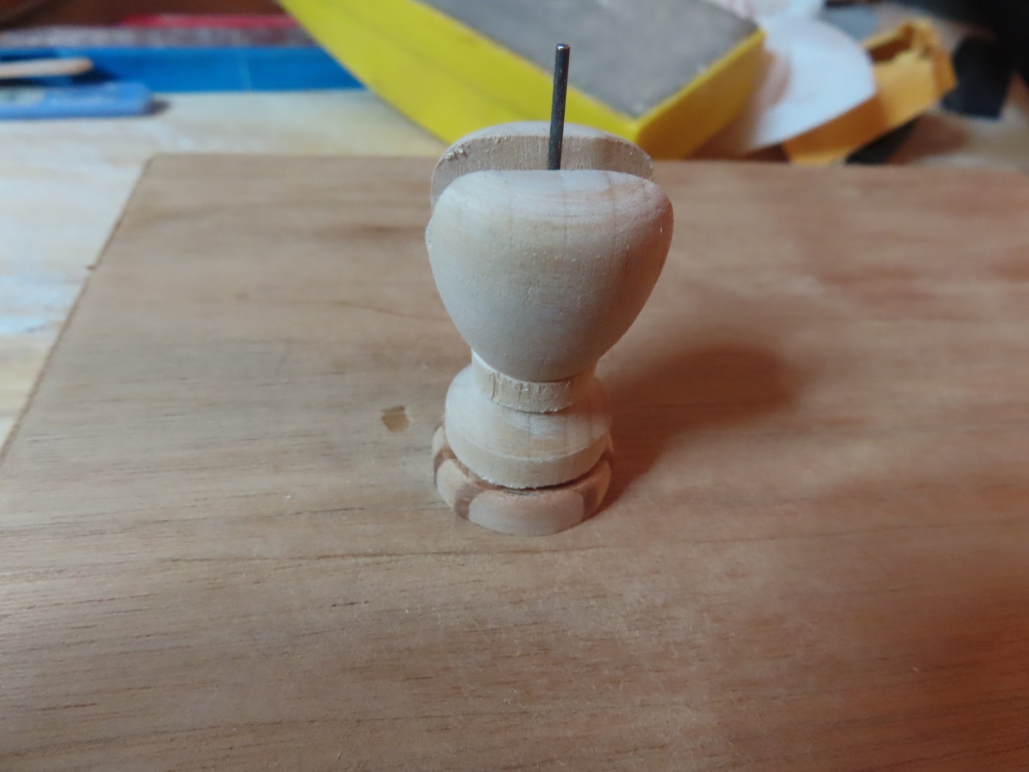
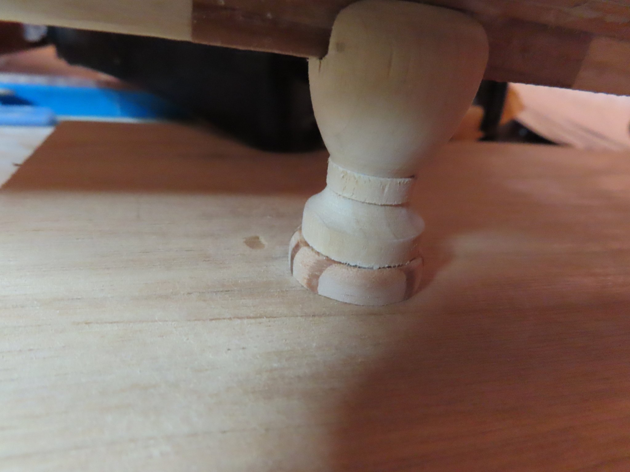
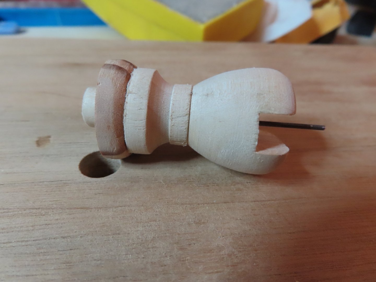
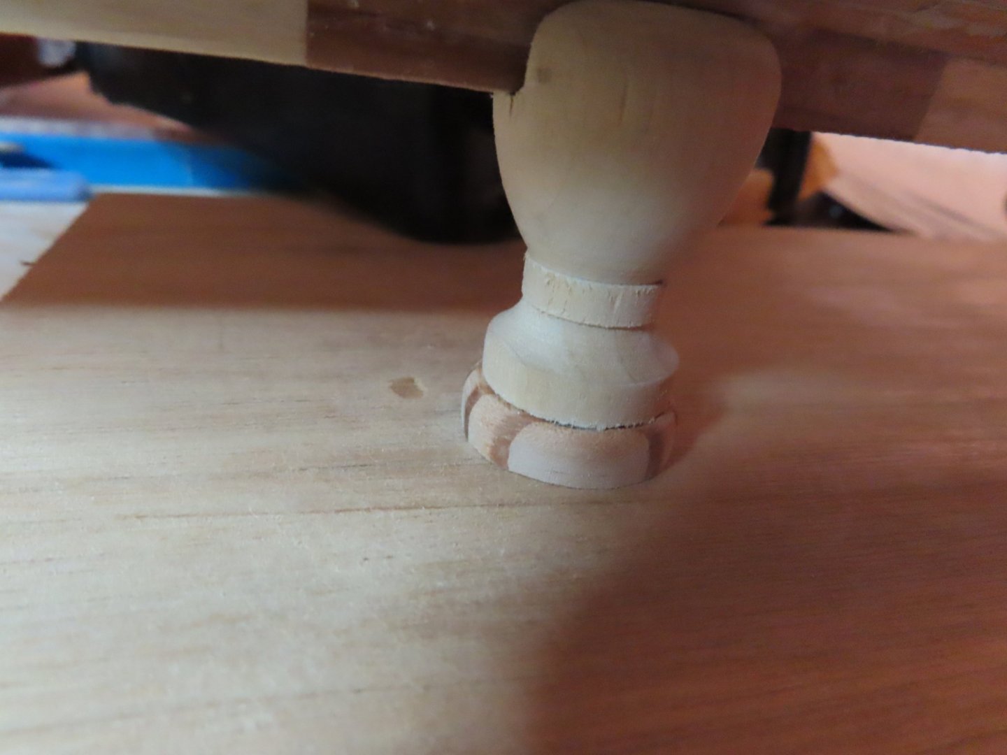
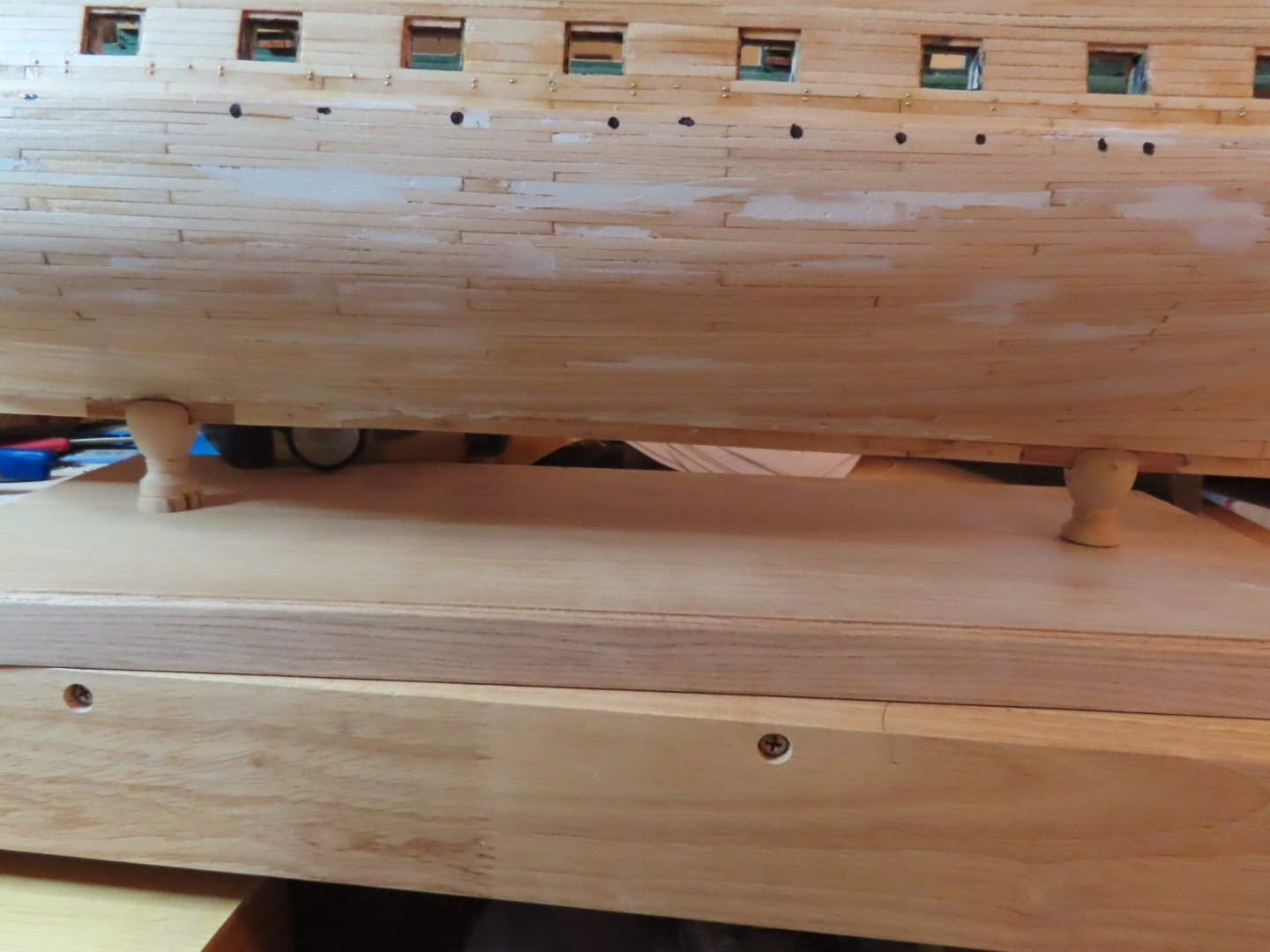
Using 3/64” dia. music wire for its strength and stiffness, two 1¼”pieces were cut using a scissor type wire cutter and inserted into pedestal. As indicated in the dry fit images below, to my surprise, it worked.


-
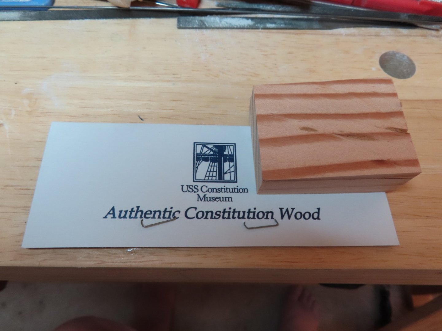
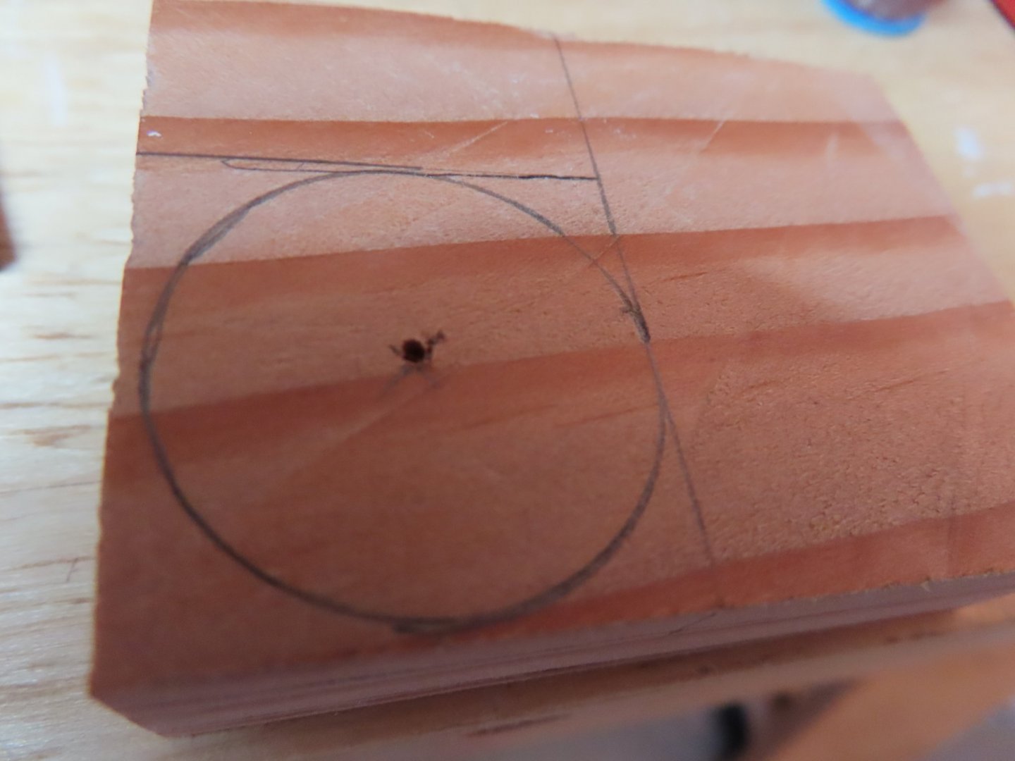
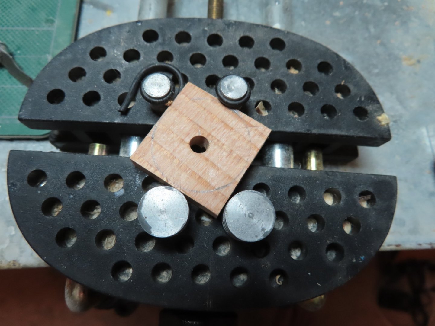
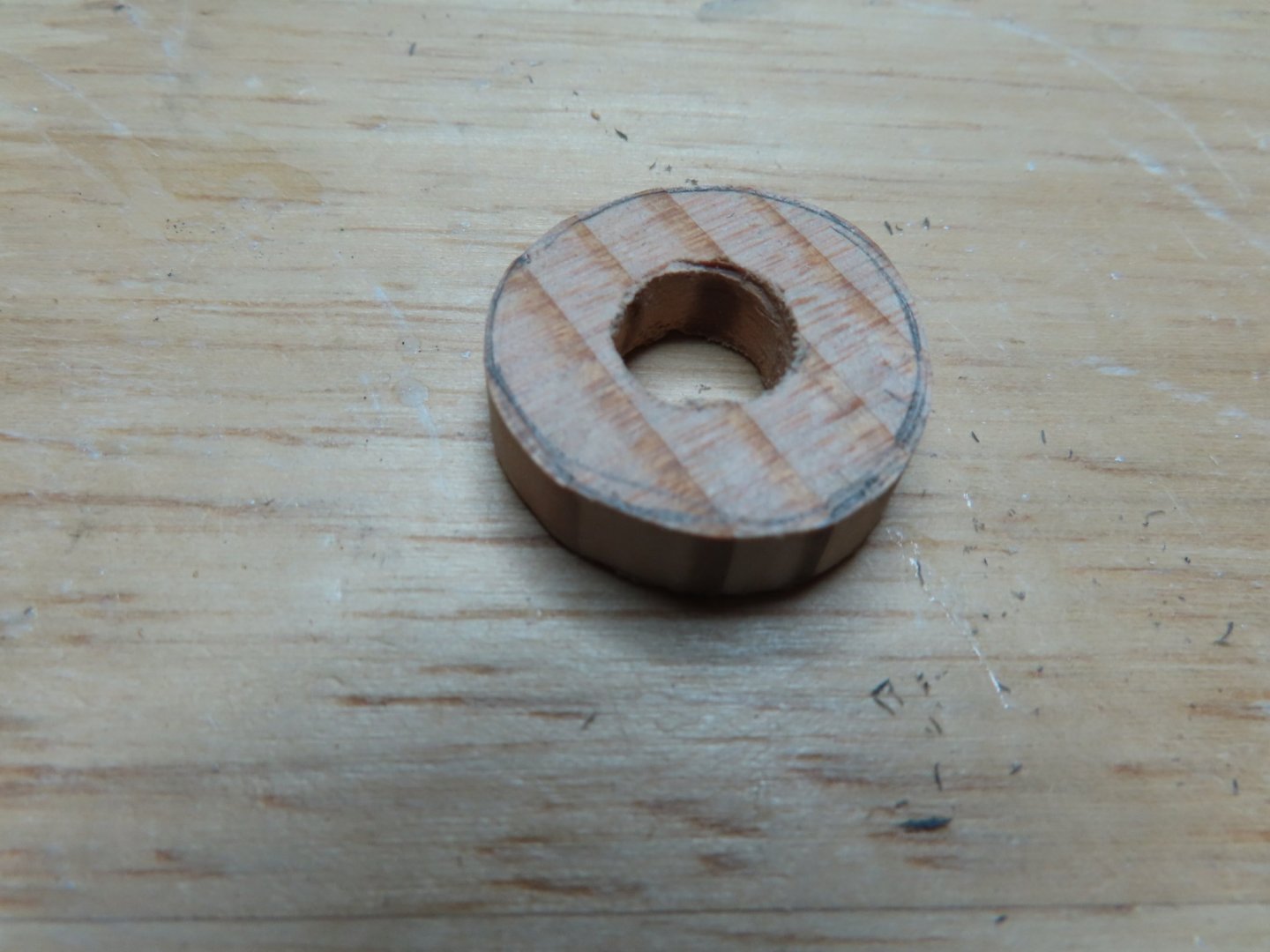
Looking at the plans, the builder will notice that the keel angles up towards the bow. The difference in height between the forward pedestal and the aft is 7/32” at the pedestal positions. This means the forward pedestal slot must be raised up. I chose to use another piece of my very limited supply of USS Constitution wood. I bought my wood around 2015-16 when it was still available to the public. I thought there would be a new supply after the ship’s last renovation in 2017, but I have not seen any for sale to the general public since. I cut a piece of the precious wood about 1” dia. and ¼” thick. I drilled a pilot hole first, then used the 3/8” bit. I hand sanded the resulting wooden “washer” so that it had a round over top edge and the proper thickness.
-
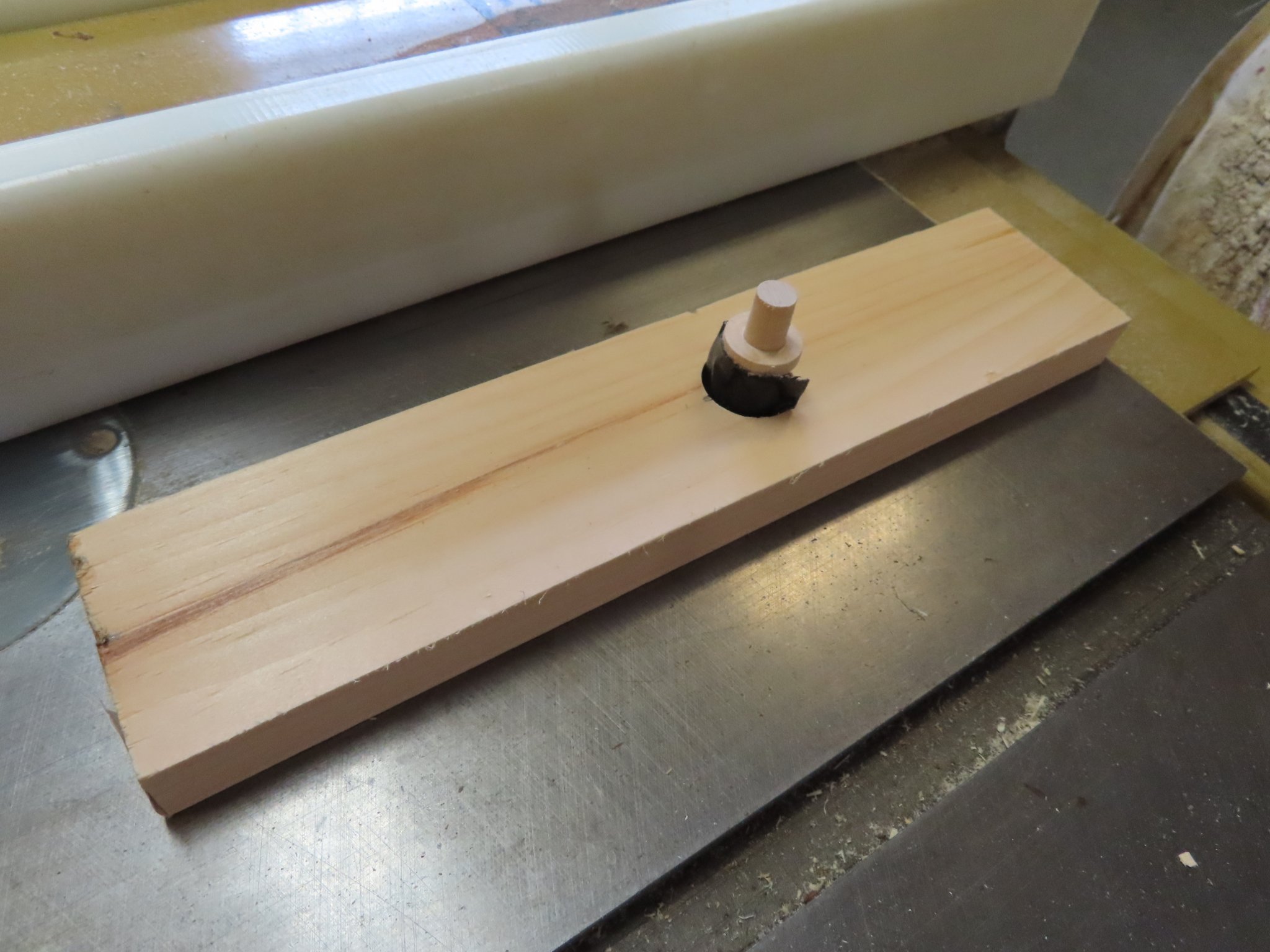
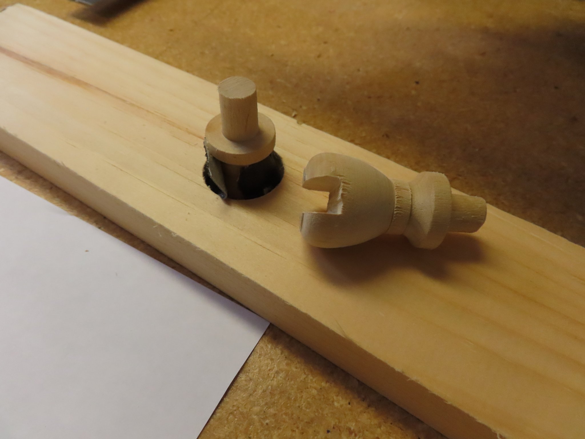
A jig was made from a scrap piece of wood by drilling a hole so that the pedestal would fit into it, top side down. A piece of tape was wrap around the pedestal to make is snug in the hole as it had no vertical surfaces. Then it was run through the table saw a couple of times to cut a slot. The results were a little rough, but nothing that couldn’t be refined. The only thing left to do was to drill a 3/64” hole down through each of the pedestal slots for the pin.


-
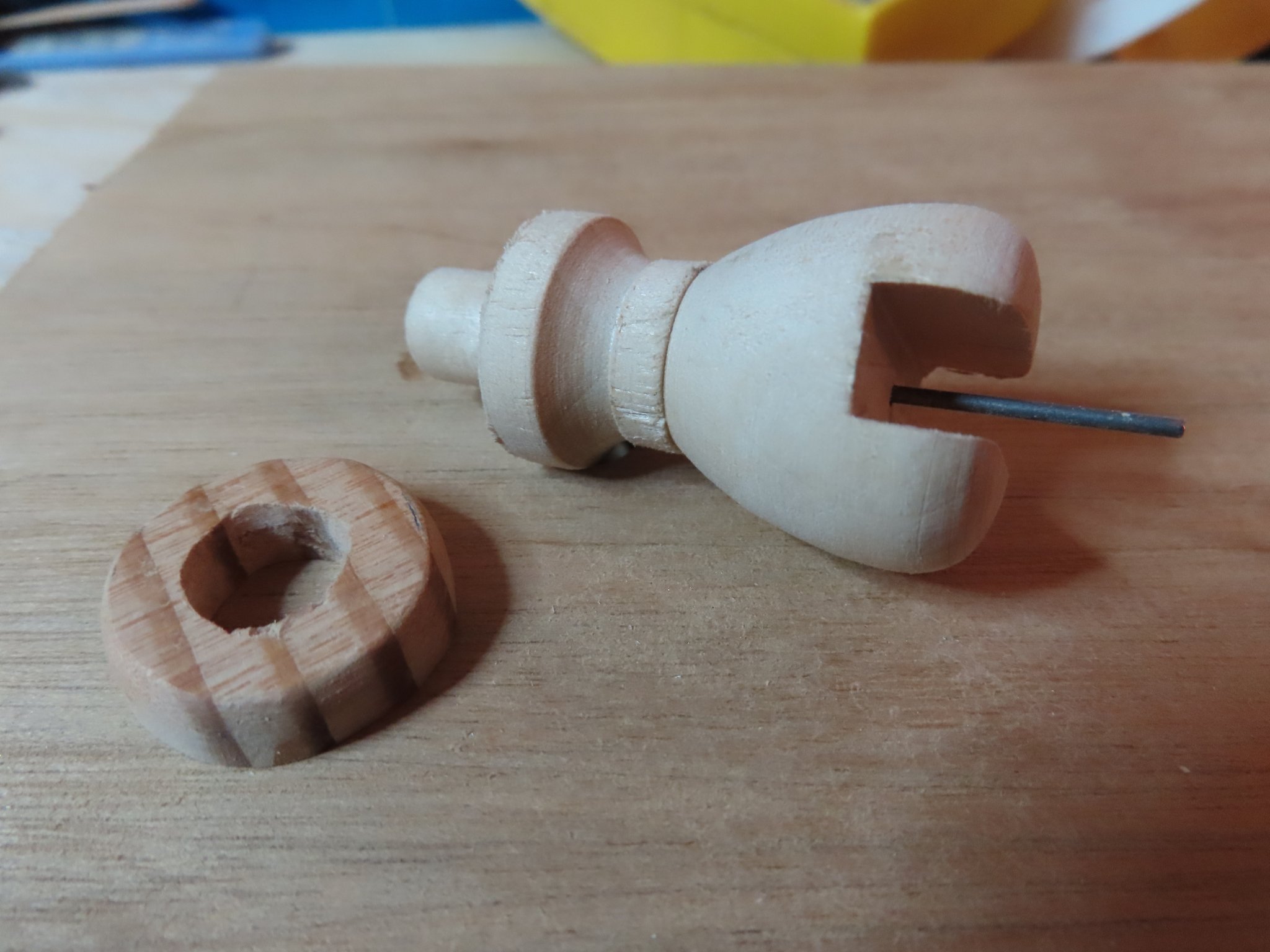
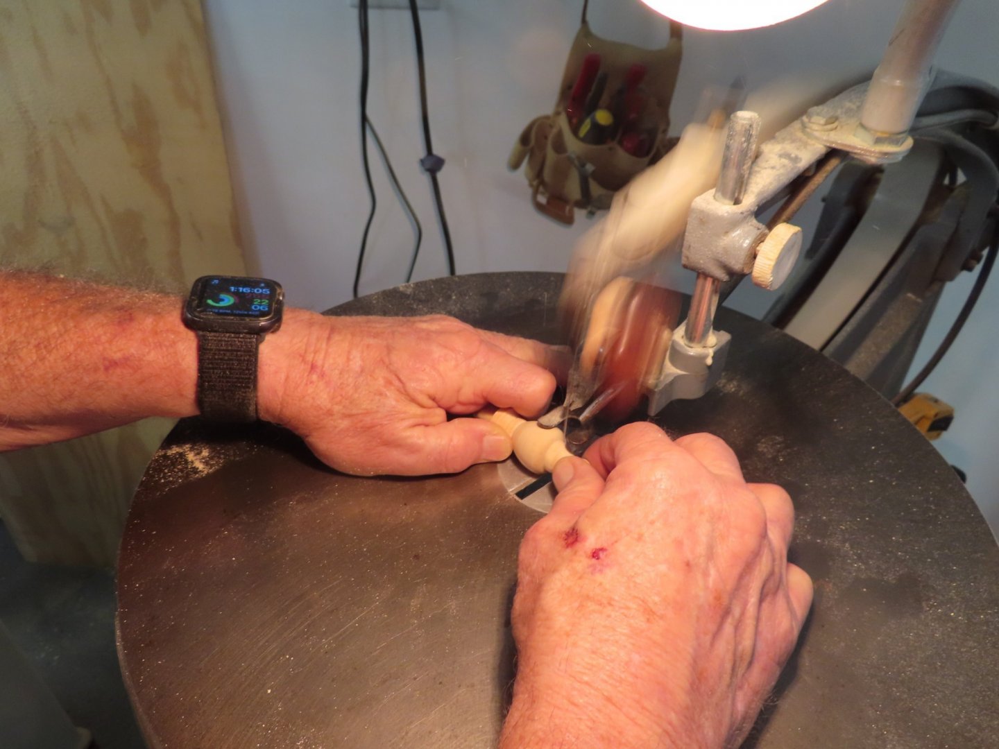
The pedestals required a bit more work. The top of the finials had to be cut off to allow for the keel slot to be cut.
-
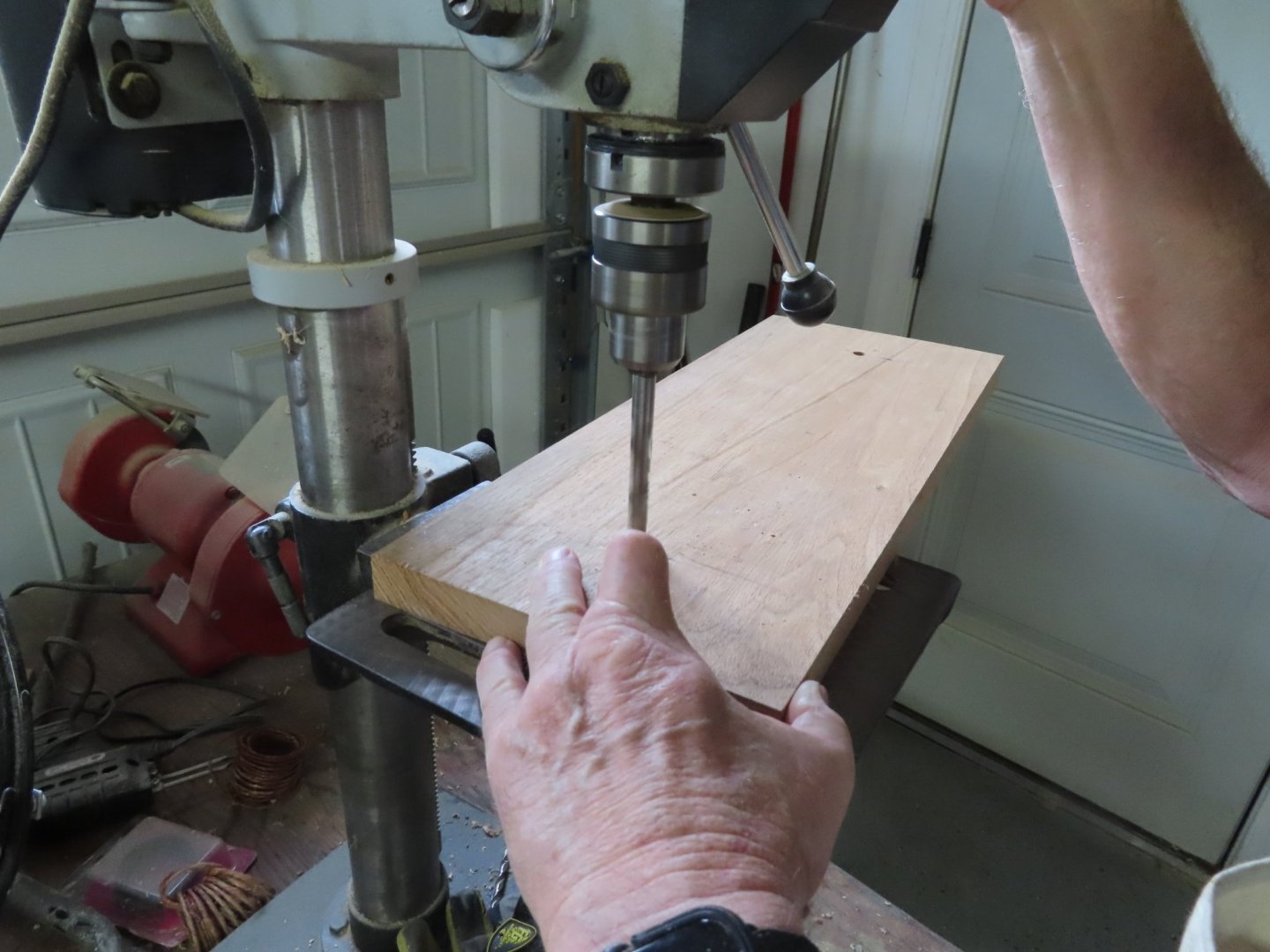
OK, now I need a board so I ask a friend of mine who use to do a lot of wood working, if he knew where I could buy some hard wood. No such luck, Home Depot and Lowes just don’t sell the fancy woods, at least where I live, but he said he would check his scrap pile. What found was a 30 year old, 11 foot long piece of White Walnut almost an inch thick and a foot wide. Yes, that would work! Because he was a wood worker, he had all the big toys. In no time flat we cut a piece of the board to 19” x 7.5” and drilled two 3/8” holes 13.75” apart to match the boat openings. The edges were routed, and sides sanded.
-
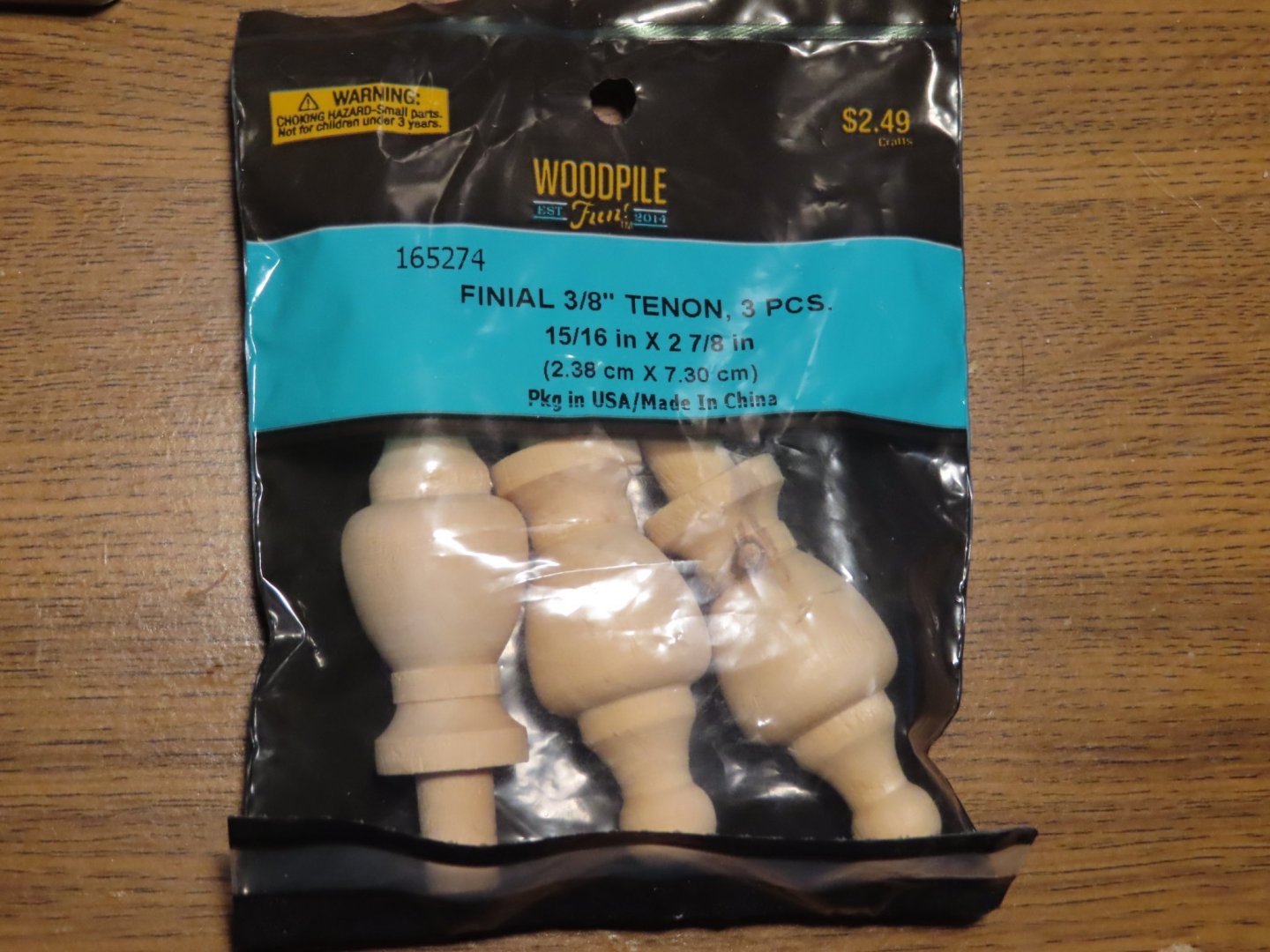
Display Mount And now for something completely different: The display mount. If any of you can remember when I was building the keel, I made mounting provisions in the keel. Specifically, I incorporated two pieces of original wood from the actual ship into the keel. Within those pieces I inserted a brass tube to accept a pin from the pedestals that were to be mounted on the base board. Originally, I thought the pedestals were going to be screwed into place. I tried buying brass pedestals from Model Expo or any other model supplier, but none had a brass pedestal with ¼” slot for the keel. I don’t have a metal lathe nor the skills to use one, so that left wood as my most practical choice. As it would happen, I ran across wooden finials at Hobby Lobby which more of a crafts store than a hobby store. But it’s all I have within 35 miles of me. The advantage of these finials is they have a tenon which means I don’t need any screws, just glue.
-
I haven’t started the quarter galleries yet, but you have given me some trepidations. Not only is it good to watch a professional model builder do their stuff, but I learn where the pit falls are by watching the less skilled builders (no slight intended) because they fall into the traps the experience builder doesn’t. In this case as you indicated, the quarter galleries have no straight lines or consistent angles. Even the laser cut pieces don’t seem to be perfect. My go-to expert for the USS Constitution build is Ken Forman (xKen), a professional model builder of wood and brass. I watched his build with awe and yet he too struggled with the quarter galleries. He built a beautiful pair of quarter galleries (post #69) only to realize later, he built them too high on the hull (post #199) which had to be ripped out and rebuilt. My congrats that you stuck it out and didn’t quit.
-
See if these links to the USS Constitution Museum helps: https://ussconstitutionmuseum.org/2015/08/25/modern-armament/ https://ussconstitutionmuseum.org/2015/11/12/constitutions-guns-a-snapshot/ https://ussconstitutionmuseum.org/2016/03/17/1906-guns/
-
I just discovered your build today and am glad to have you back and your build log to read. I think the last time I communicated with you, was over some errors in Mr. Hunt's practicum for the Rattlesnake. I think I drove you a bit crazy. You were so gracious, I felt guilty asking for the missing wood. I still have a lot of the wood I purchased and it is a pleasure to work with. I still can't cut a long piece of wood with your precision, and I use the Byrne's saw! Jon
-
KirbysLunchBox, I can't wait for the paint job too, but that's still in the future...how far, I'm not quite sure. I.ve got to install the castings along the hull, as well as build the quarter galleries among other stuff I haven't thought about yet. There is an old truism: No matter what you have to do, you have to do something else first.
-
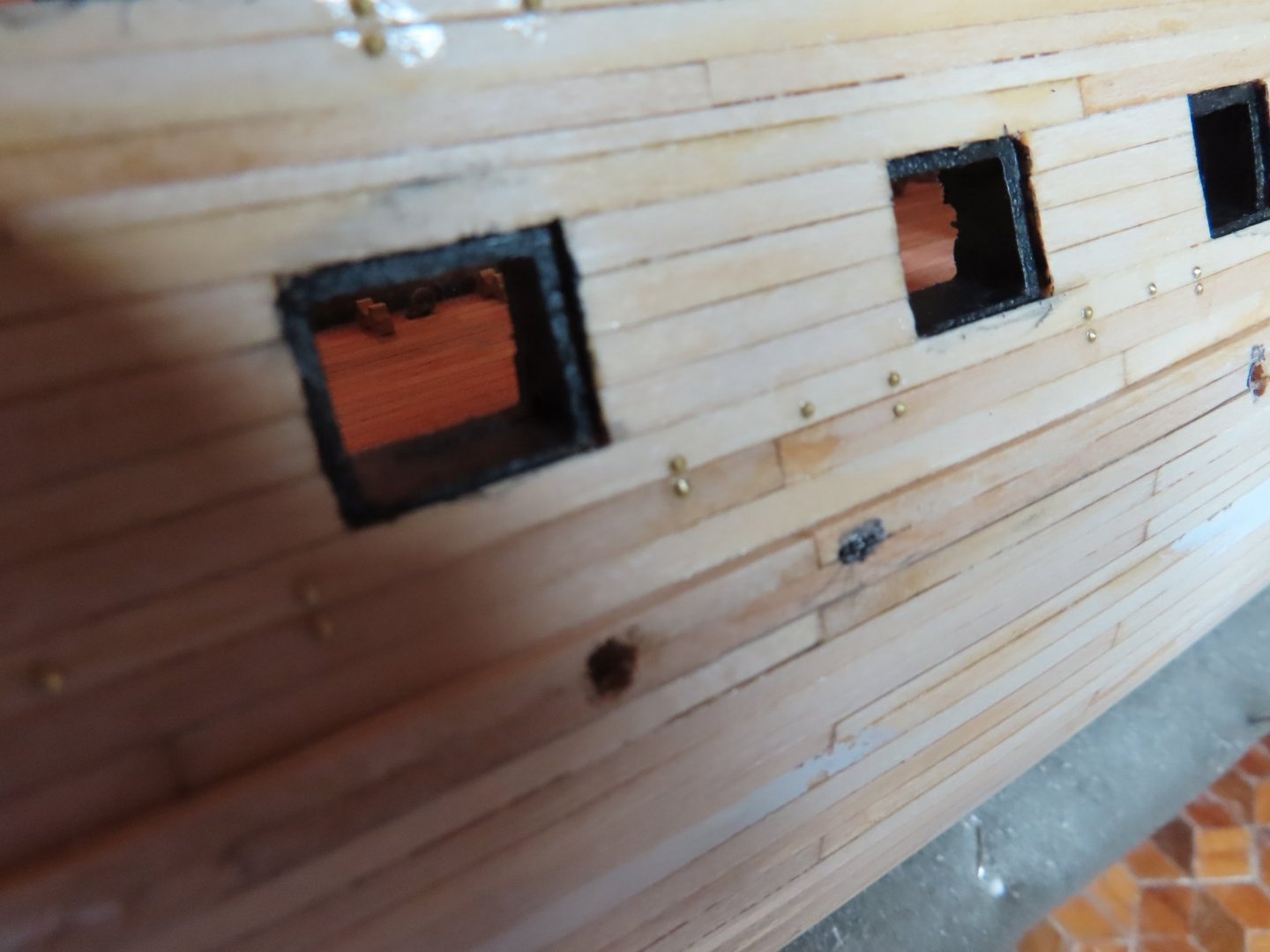
The hull gun port “bolt heads are all installed. I had to make 350 pseudo bolts heads including ones I lost or were mis-formed. I didn’t take an overall picture because they would be difficult to see. The previously post close up give you an idea of what they look like.
-
Thank you both Kirby and Tom, but you have to be juuuust a little bit nuts for this kind of detail.