HOLIDAY DONATION DRIVE - SUPPORT MSW - DO YOUR PART TO KEEP THIS GREAT FORUM GOING! (Only 13 donations so far - C'mon guys!)
×


JSGerson
-
Posts
2,611 -
Joined
-
Last visited
Content Type
Profiles
Forums
Gallery
Events
Everything posted by JSGerson
-
 One more to go!
-
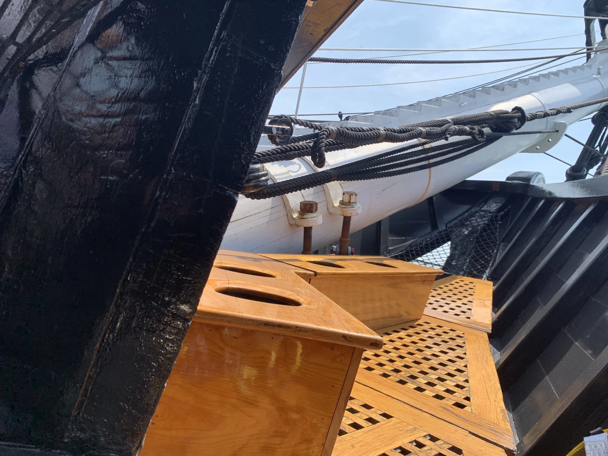
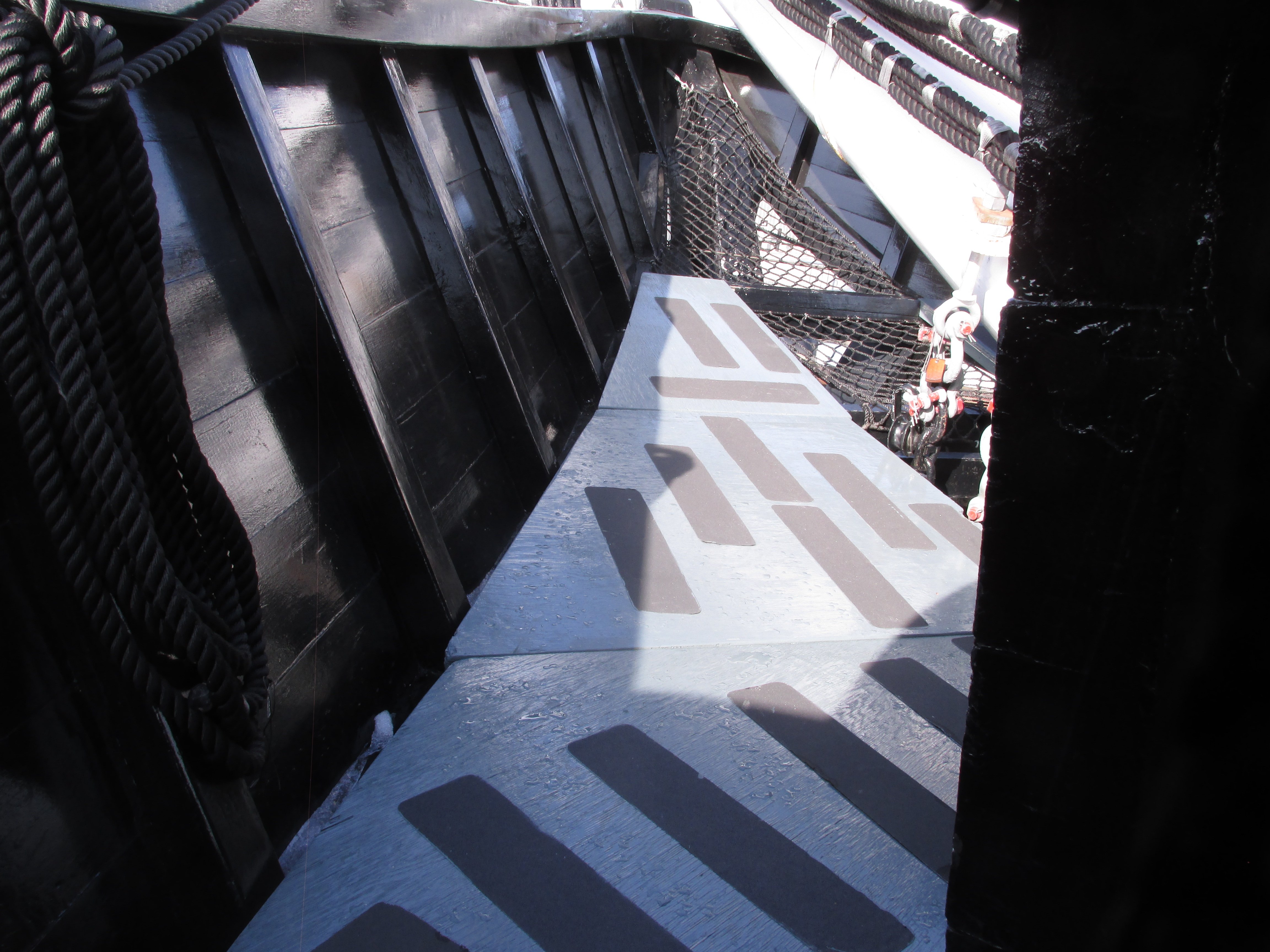
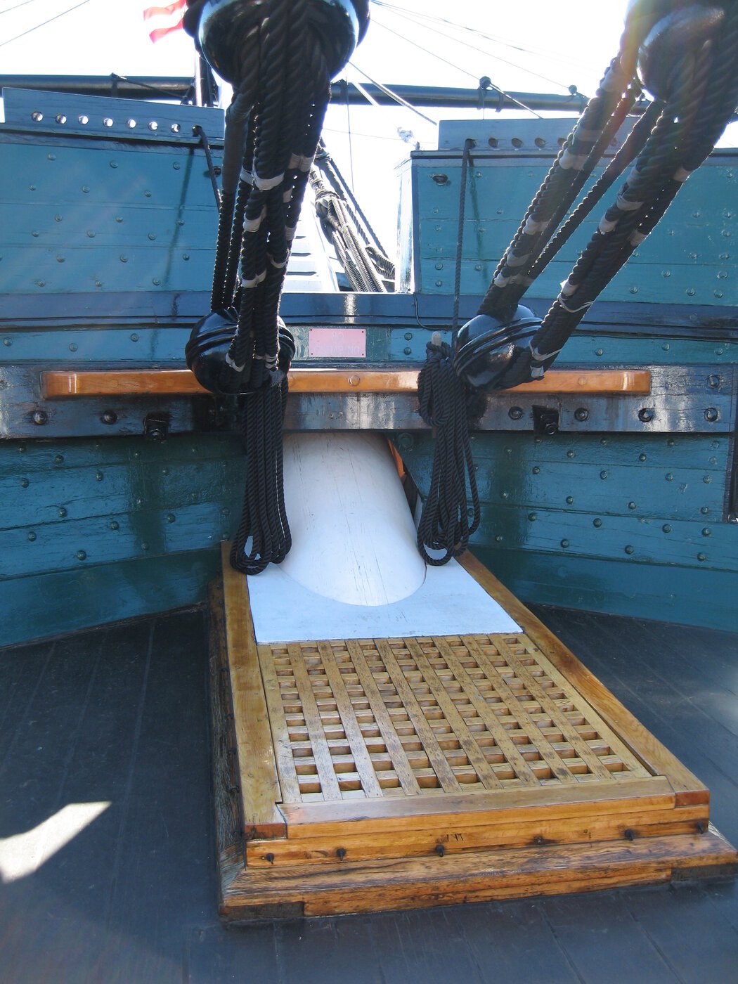
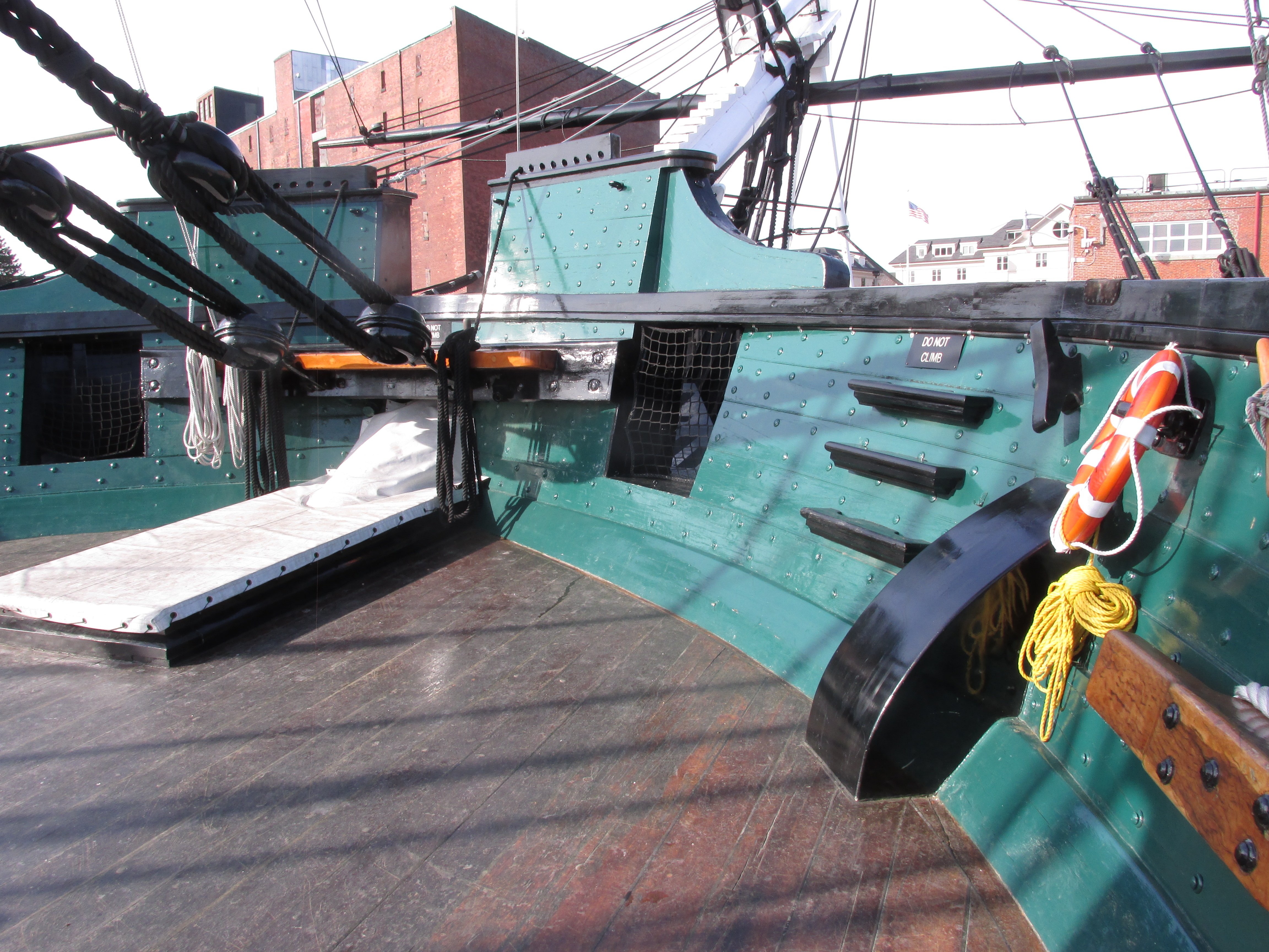
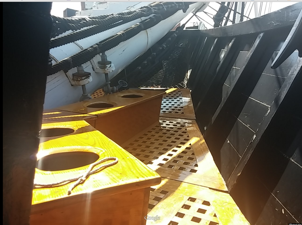
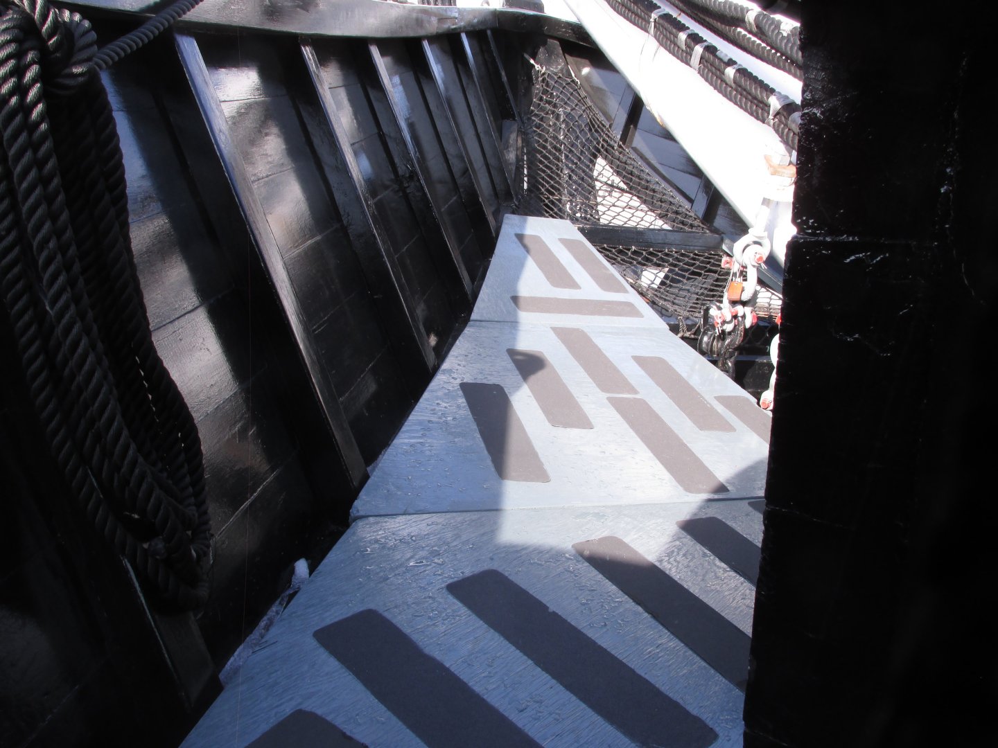
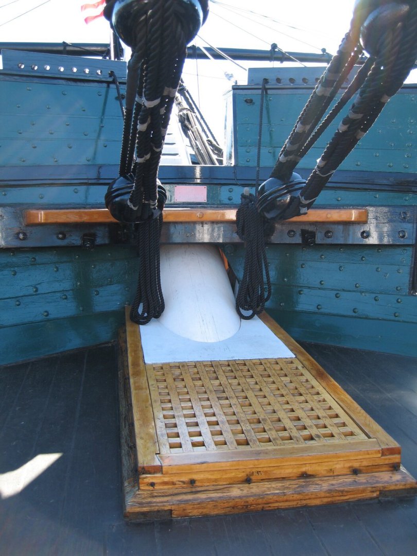
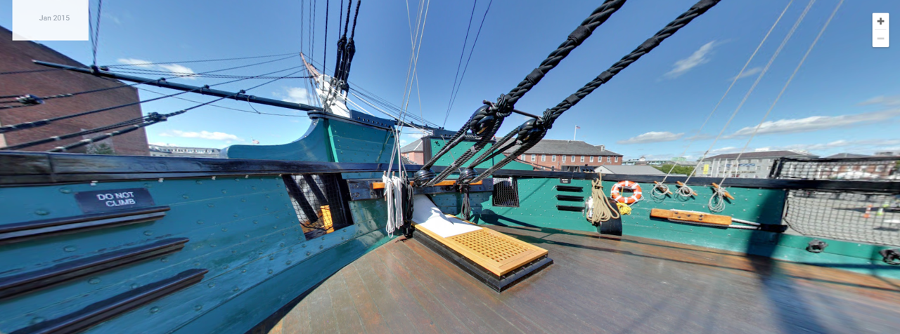
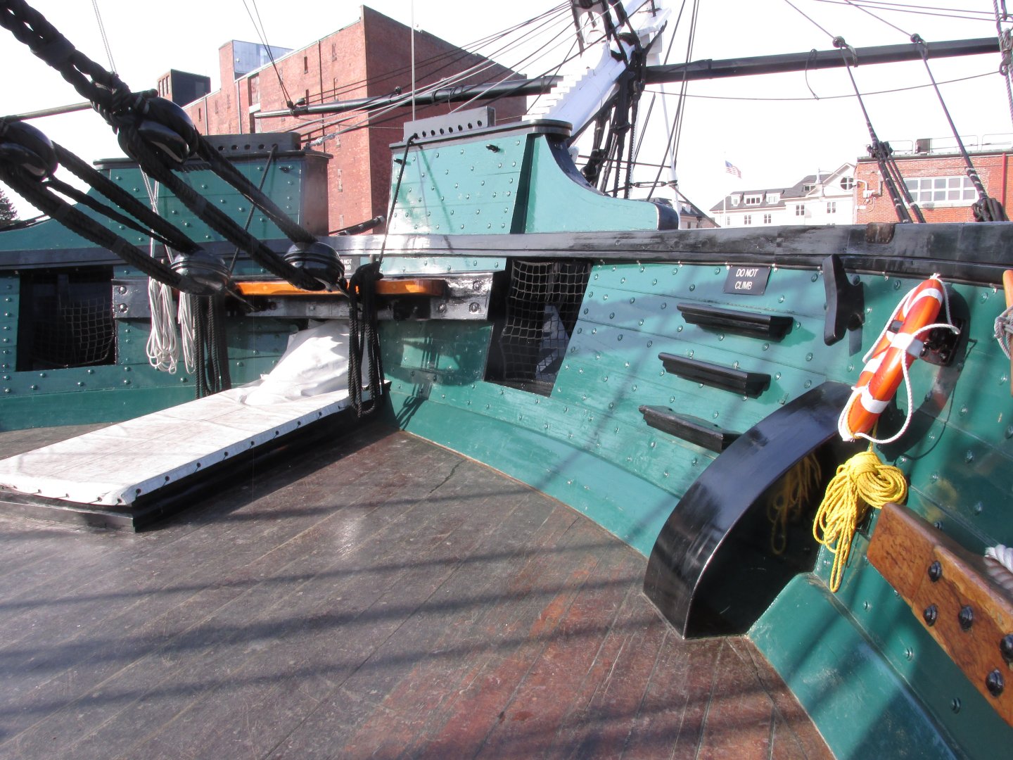
The Constitution's seats of ease are some of the hardest images to find. That's because that area is off limits to the general public and is block from direct view by the forward bulwarks. I know this, because I tried to take photos of it 2015. But over the years, I managed to accumulate a few passable but not great images. My photo below is of the port side where the grating is covered, The images of the grating on the starboard side were taken by others. Jon

-
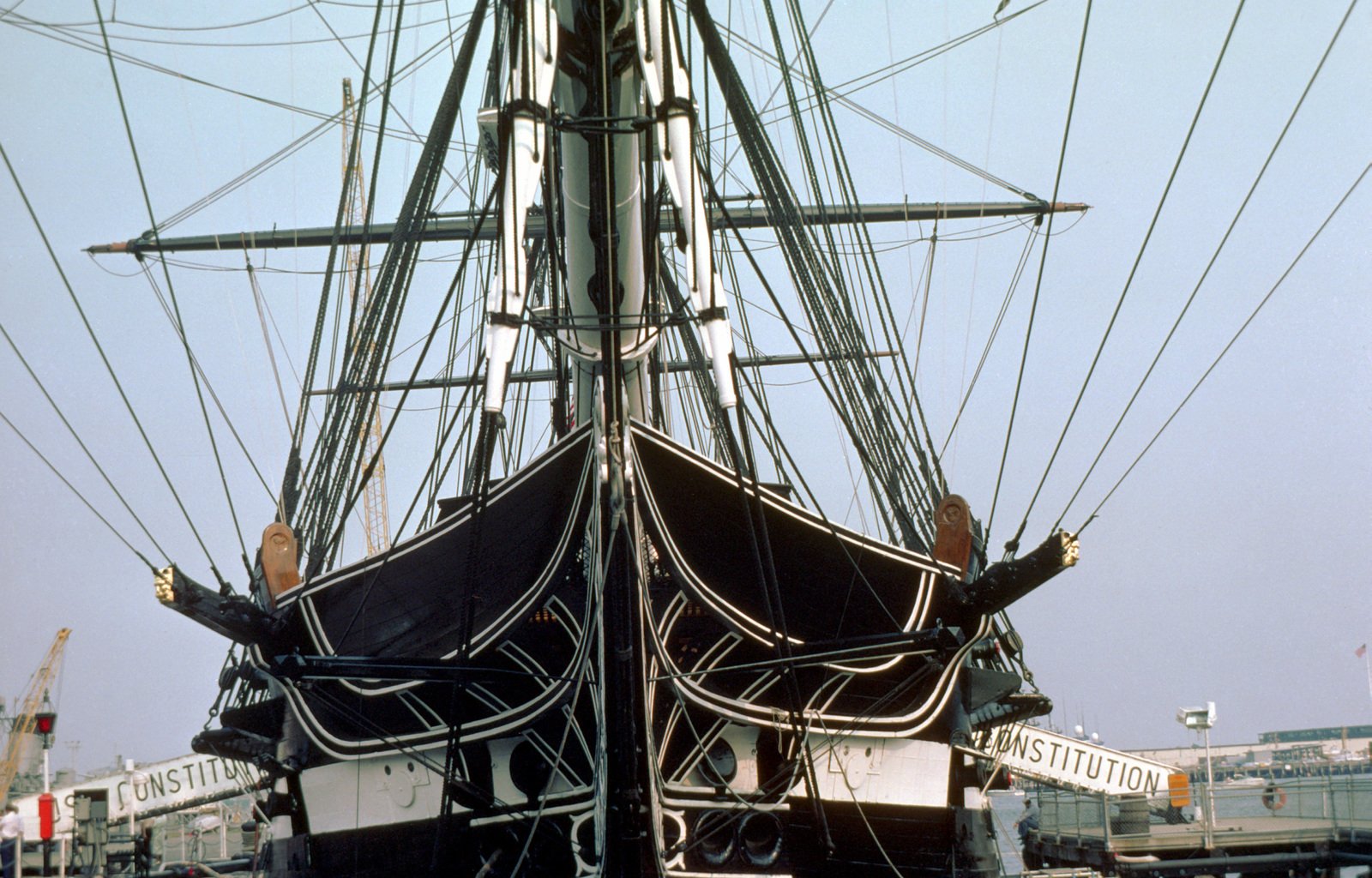
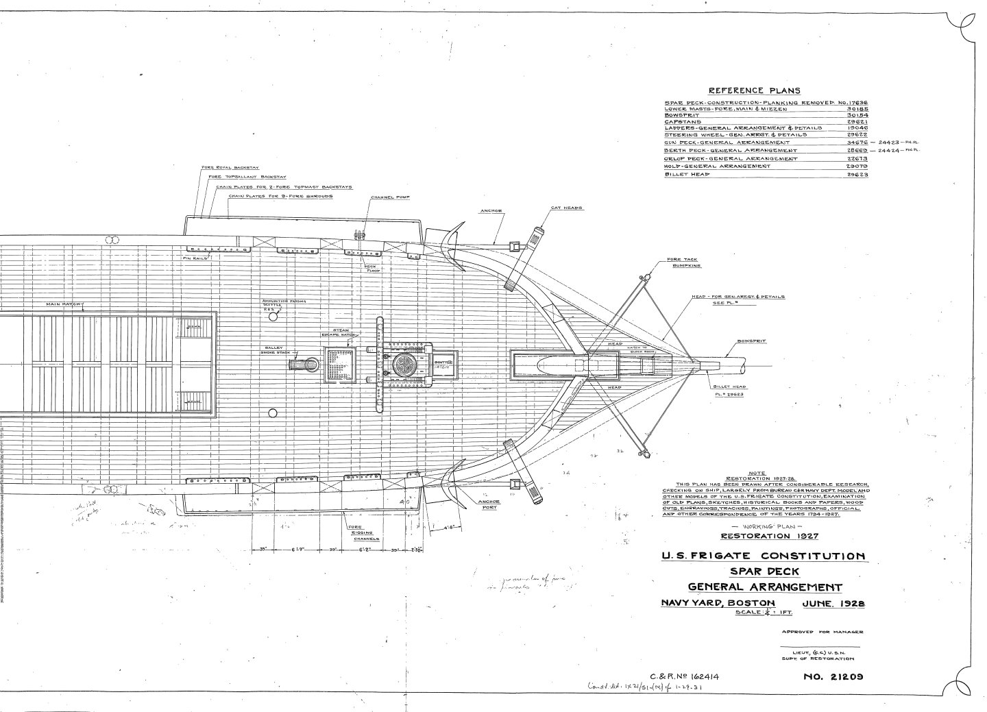
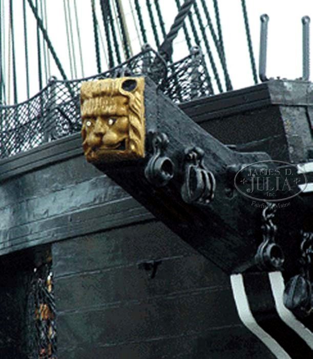
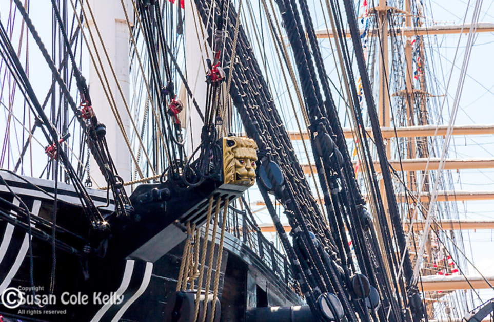
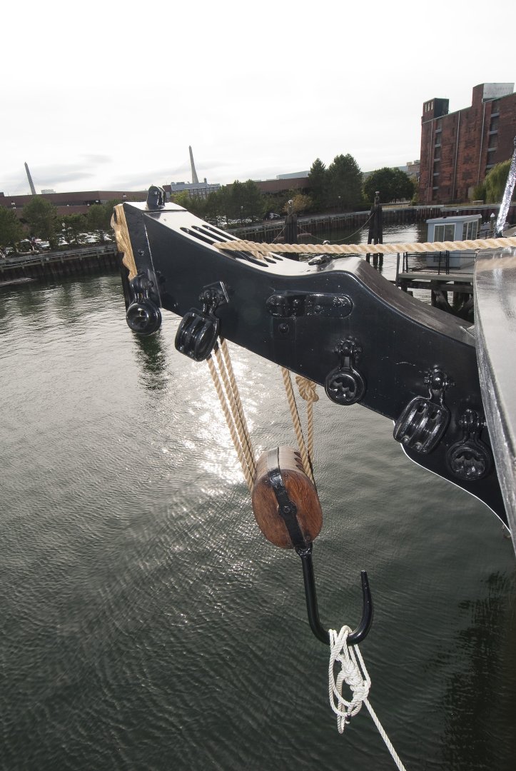
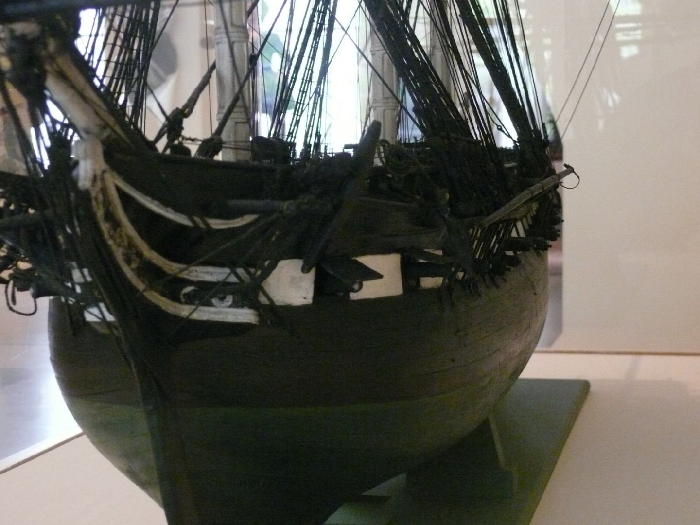
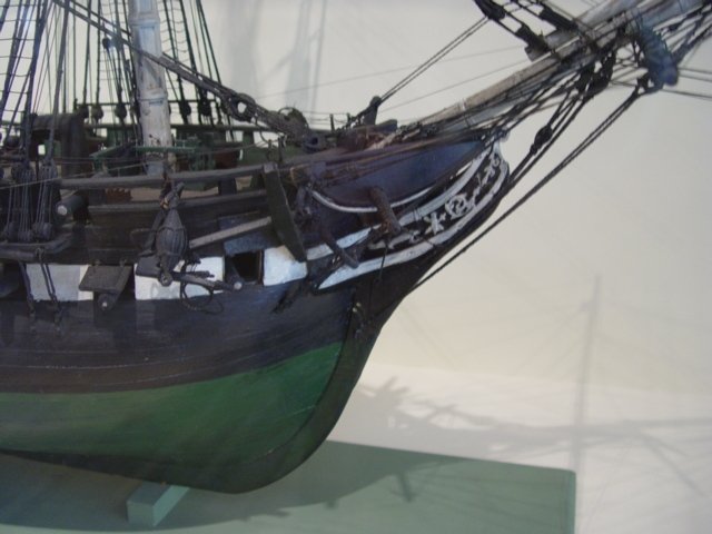
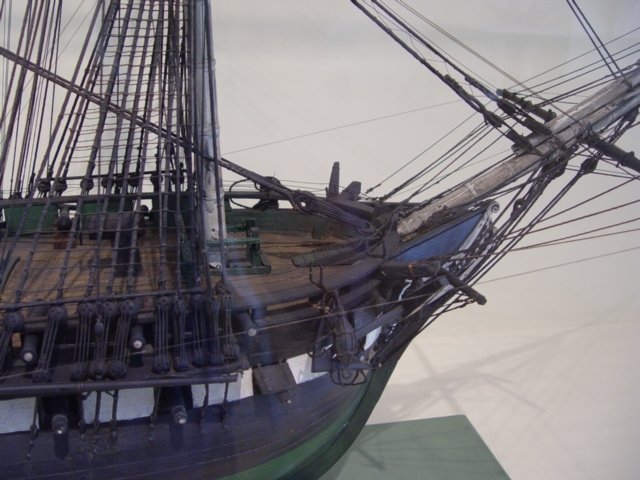
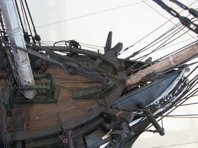
Here are a few images of the bumkins (boomkins?) and the 1927 plan of the bow clearly showing them, should elect to install them. I did on mine. Jon
-
Yeah, I edit the logs for easy readability, grammar, spellings, etc. like you do as well, Sgt. Joe Friday!😁 Jon
-
I write my log in Word first because the way I compose, I have to do a lot of re-writes for it to make sense, check spelling, missing words, grammar, logic, etc. Then I let it sit for a bit to ferment as I call it. I do this a few times. It is amazing how many errors pop up when I read my prose fresh. Then, when I feel somewhat satisfied, I post it. Jon
-
I'm with you Peter, how do you download build logs to PDF? I've been copying and pasting to create Word copies of other people build logs, a very laborious process. Of course the upside of the Word copies is that I can word search complete logs with the click of a mouse. Jon
-
There are a few questions I have about the storage of those hammocks: Are the bundles identified so each sailor gets his own hammock back or do they get what they get? Don't the hammocks get wet from salt spray and rain? Who wants to use a wet hammock? Do the hammocks get washed or rinsed in the sea? These ships are not what you would call sanitary. Jon
-
USS Constitution by mtbediz - 1:76
JSGerson replied to mtbediz's topic in - Build logs for subjects built 1751 - 1800
What method are you using to the flatten the brass wire to get a consistent result ...vise, hammer & anvil, ??? Jon -
Unegawahya, that is exactly why I was contemplating adding the hammocks to my model. If the crew was on board ship, the hammocks would be stored there during the day. How I would model them remains open at this point as I have not thought that far ahead, but I've seen a variety of methods to create them. I have plenty of time to work things out. Jon
-
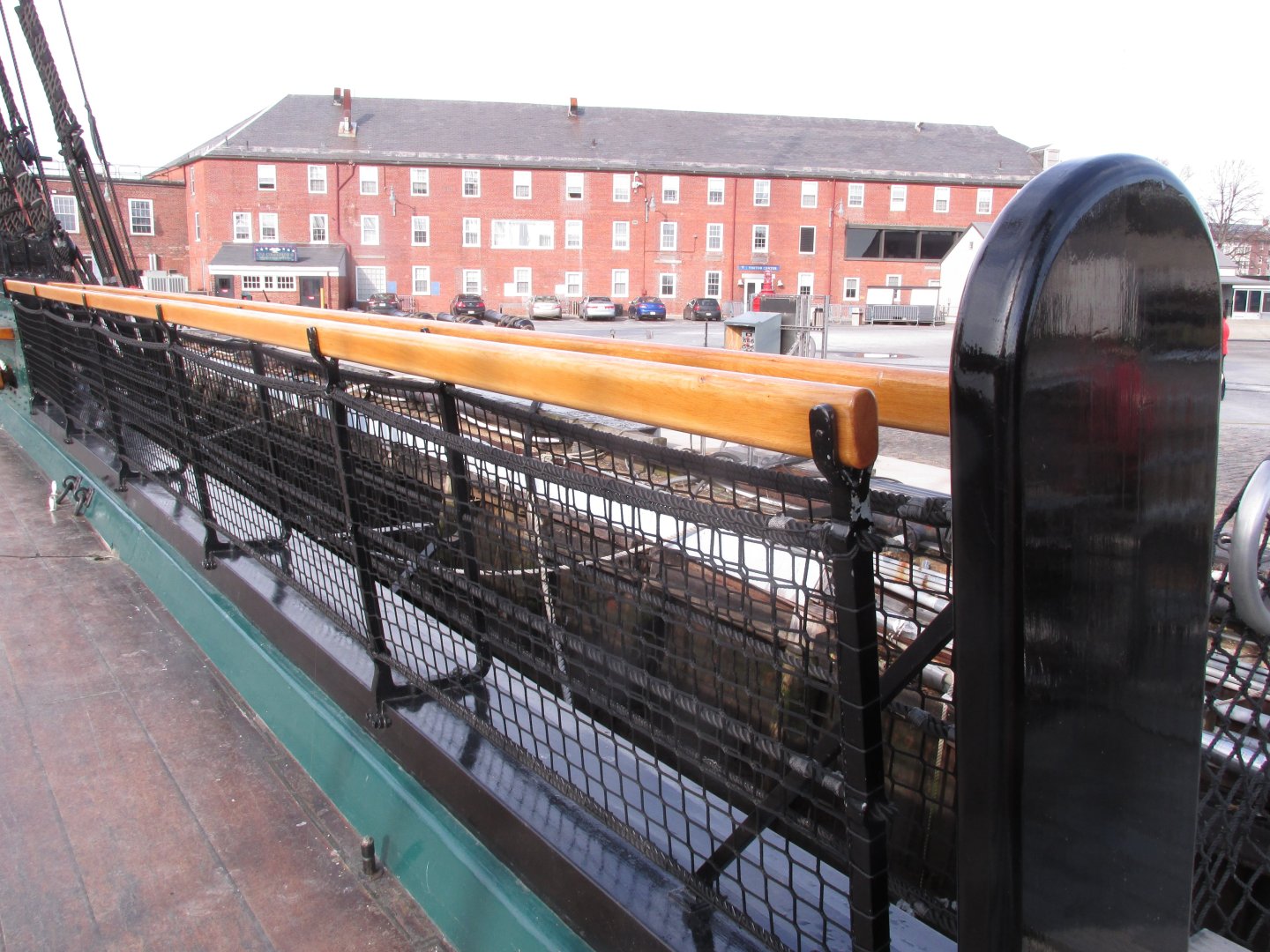
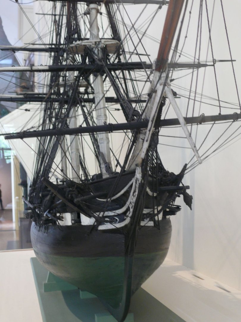
Hey, I'm not the holding anybody to a rule book😁! The builder is the captain of the way his ship looks. The present day ship does have the hammock stanchions and netting. What it doesn't have are the the actual hammocks bundles in the netting. I assume, they are not there for practical reasons like cost and upkeep. I am thinking about adding the bundled hammocks to my model when the time comes. My philosophy is I add nothing to my model (that I am aware of) that are for tourists (safety equipment, electric lighting, loud speakers, gun port netting, etc.) and add stuff that would be there if the tourist weren't (e.g., hammocks, gun rigging, etc.). Both you and Peter have beautiful models, just different styles. Jon
-
You might want to add all of the eyebolts, blocks, and carvings now, off ship while it's easier to do before, installing the catheads to the hull. Jon
-
That's why it's called "fiddly work." 😁 If you want real fiddly work, try working on the canopy frames!😅 Jon
-
The 1/32" eyebolts I have from Model Expo are made from 1/32" brass wire with the eye interior opening of approximate 1/32" diameter. This translates to 2.4" interior eye diameter made from 2.4" diameter rod at full scale. So yes as Mustafa said, the smaller the belter... depending on its application. Jon
-
Here are a few more Jon 1910 - NH 54010.tiff
-
Thanks for trying Jon
-
Seems Mr. Hunt missed it too. Always glad to help Jon
-
Kurt, where may I see more pictures of Herb Ebson's and Jerod Matwiy's models?
-
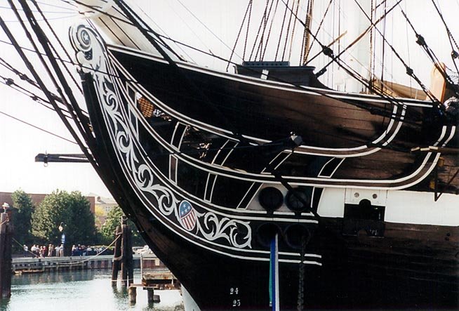
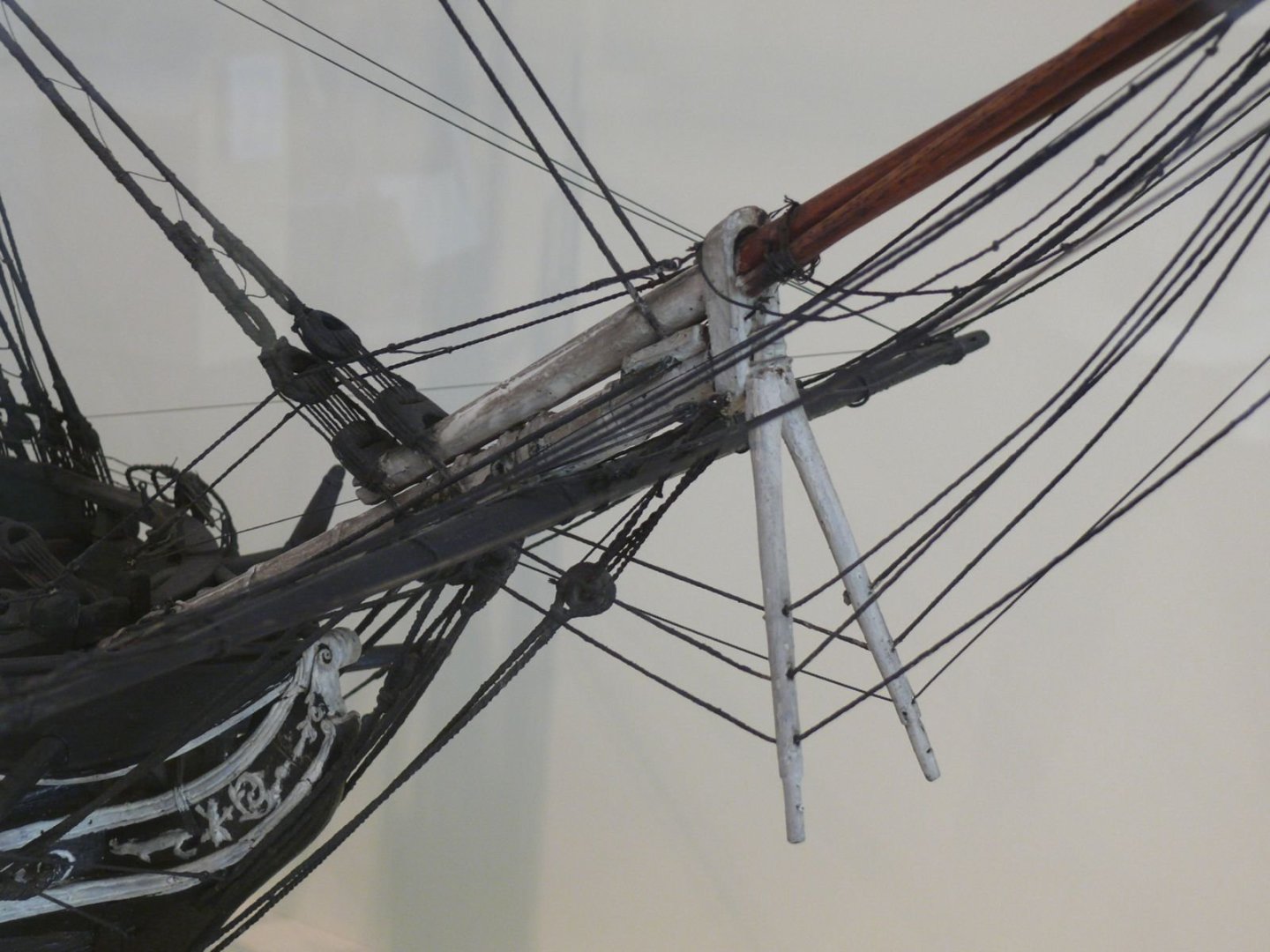
Take a look at plan #3. In the center of the plan there are the end views (combined forward and aft) with the title "Hull Planning Layout." It shows clearly the gap in the top gallant bow rail. Clearly, Mr. Hunt made a boo boo here. But I forgive him; he is human after all. I think he was rushing to finish his practicum. Jon
-
Only 5 years? I'm into mine 8 years and am now just starting the spar deck. I figure another 3 years for me.😏 Jon
-
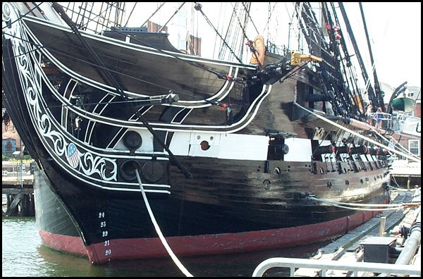
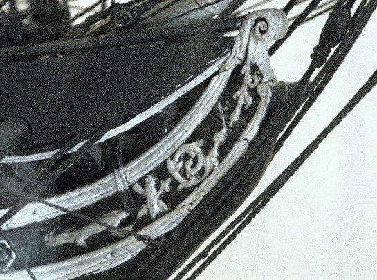
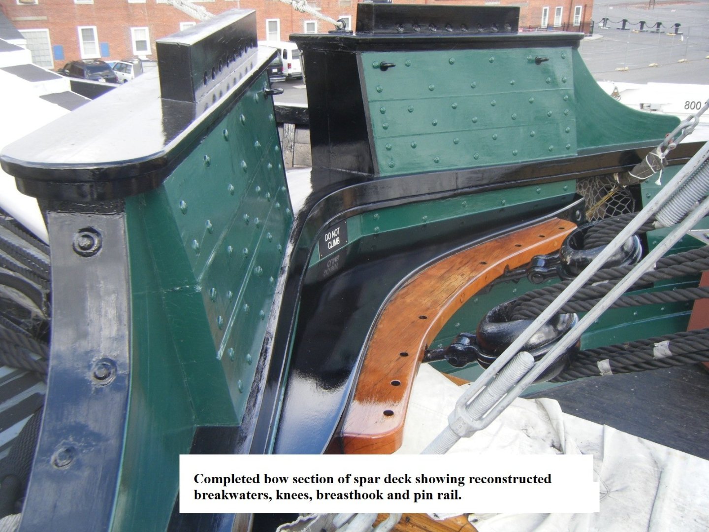
Peter, I have said many times on other build logs, that Mr. Hunt never fully built his Constitution model, but just enough to show how it should done. He also skipped some details and not others. In the case of the bow top gallant bow, he messed up. As you pointed out on his model, the flair on either side of the top bow gallant rail is missing. And what isn't missing should be, specifically the space above the bowsprit as it passes through the rail. Mind you, I'm not putting down his practicum, it's got a lot of good stuff but it's not the end all reference. Always, always check the actual photos when you can. And if you can't find photos, ask me, I might have what you are looking for. Jon
-
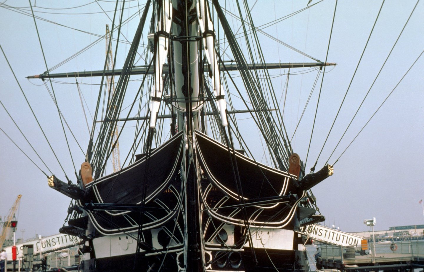
OK, now we know that Mustafa is building the 2015 version (no top gallant rail except for the bow), you are building the 1927 version (top gallant rail all around), and I'm building the present day version (no top gallant rail at all) of the USS Constitution. The other two most common versions are 1797 launch and the War of 1812. This is why I have always said you must decide what era you are modeling right at the beginning of your build and stick to it. Note, the MS kit is based on the 1927 restoration and BlueJacket and Revell are based on 1812. I don't know what the others (that I know about) are officially based on (Mamoli, Mantua, Constructo, Billing Boats, and Scientific). Jon
-
I've have never molded anything, but I'm sorry, nothing is "fairly easy." There must be a bunch of details that must checked everything must be set just right to obtain the optimum results. You did good. You proved casting the part is an art and the painting of the part's fine details was wonderfully done. You sir, are an artist! How did you do get those painting results? Your brush must of had just one hair😁 Jon
-
My fears are allayed, it looks great. Jon
-
USS Constitution by mtbediz - 1:76
JSGerson replied to mtbediz's topic in - Build logs for subjects built 1751 - 1800
Now why didn't I think of that. Great solution! Jon -
Beautiful and the rigging securing the boat to the the hatch is nice and clean. Well done! Jon