HOLIDAY DONATION DRIVE - SUPPORT MSW - DO YOUR PART TO KEEP THIS GREAT FORUM GOING! (Only 44 donations so far out of 49,000 members - C'mon guys!)
×


JSGerson
-
Posts
2,618 -
Joined
-
Last visited
Content Type
Profiles
Forums
Gallery
Events
Everything posted by JSGerson
-
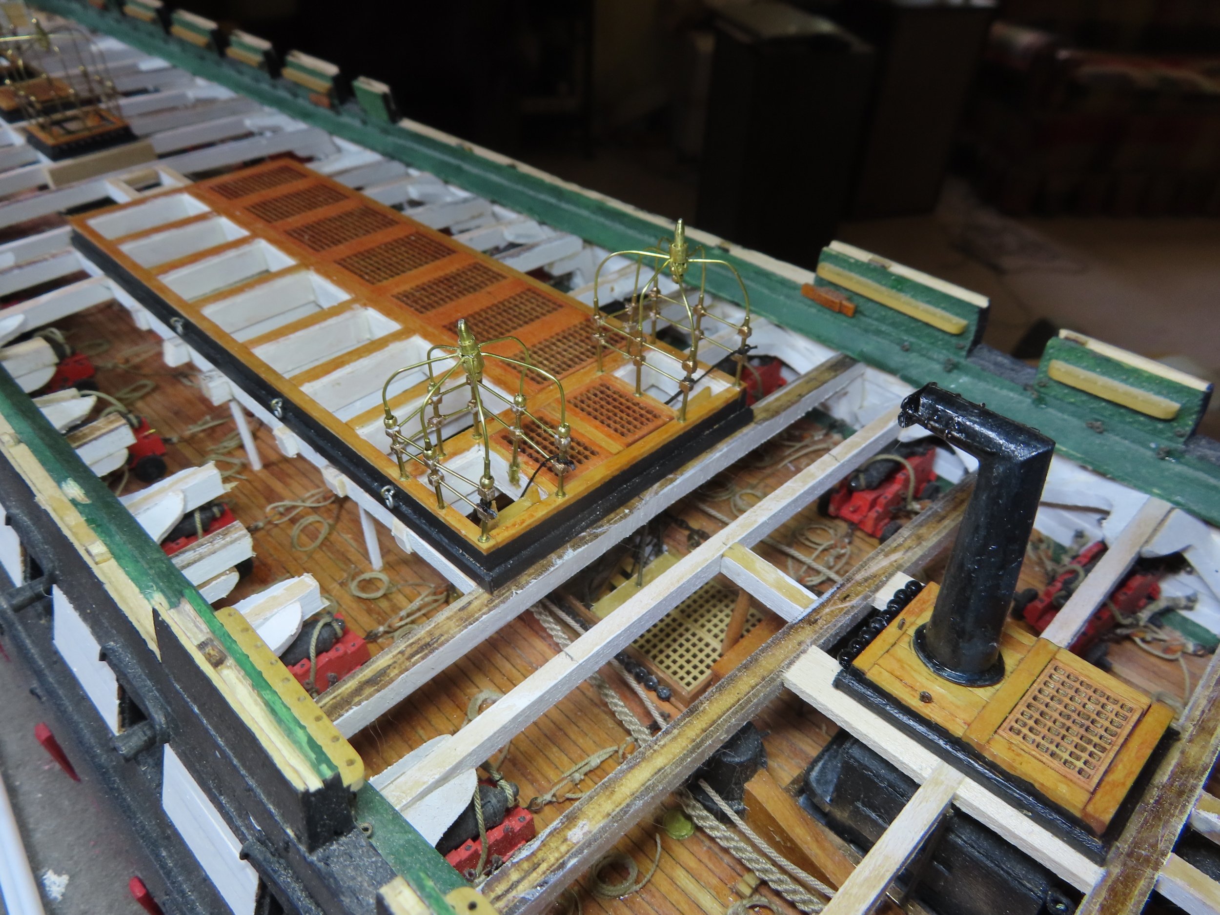
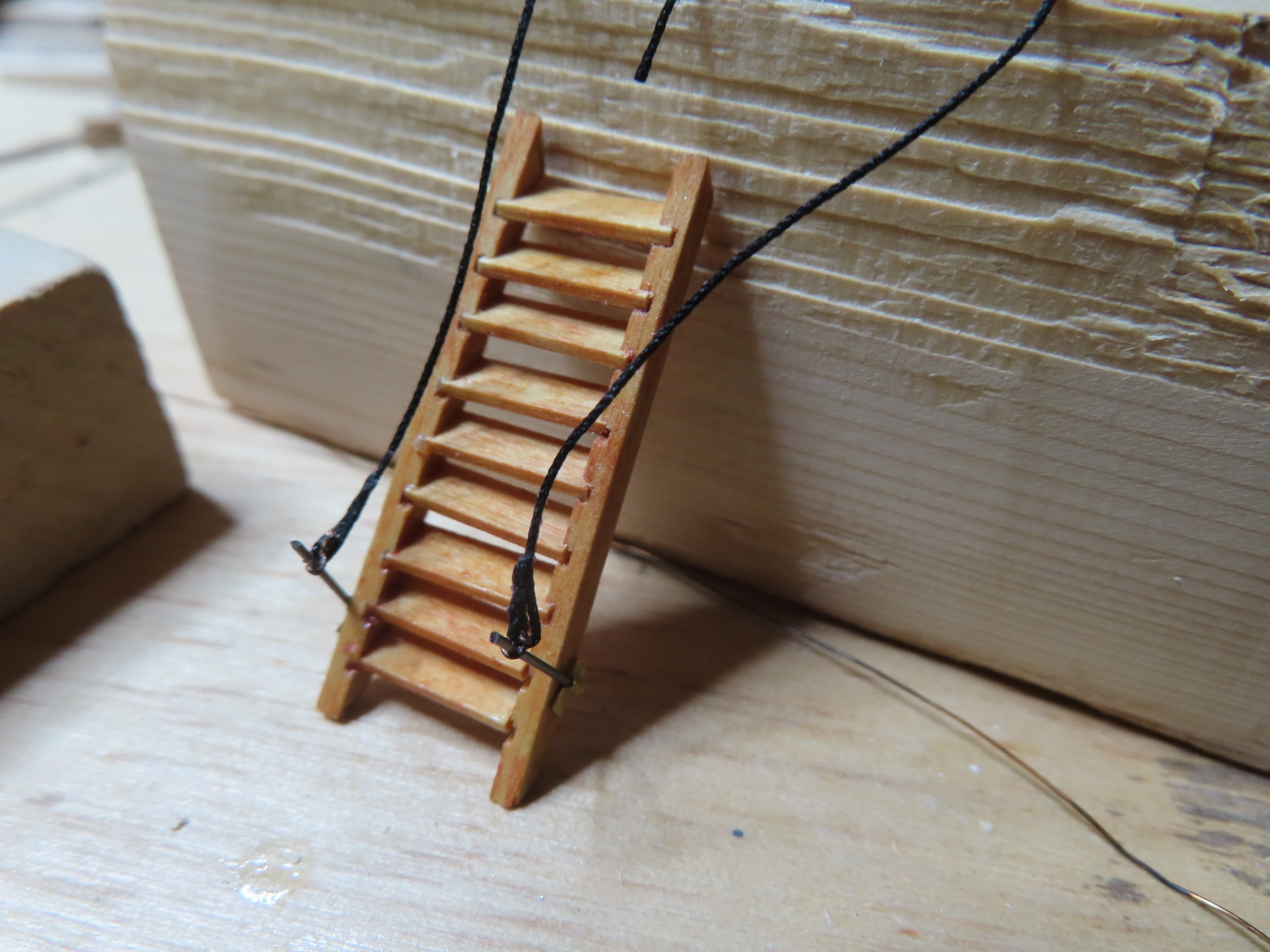
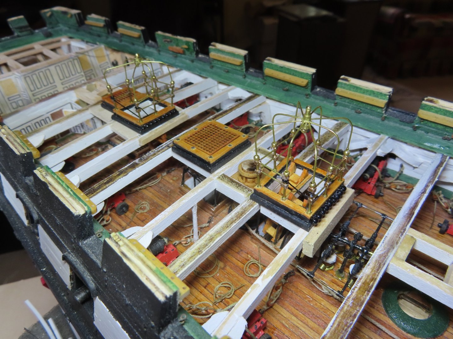
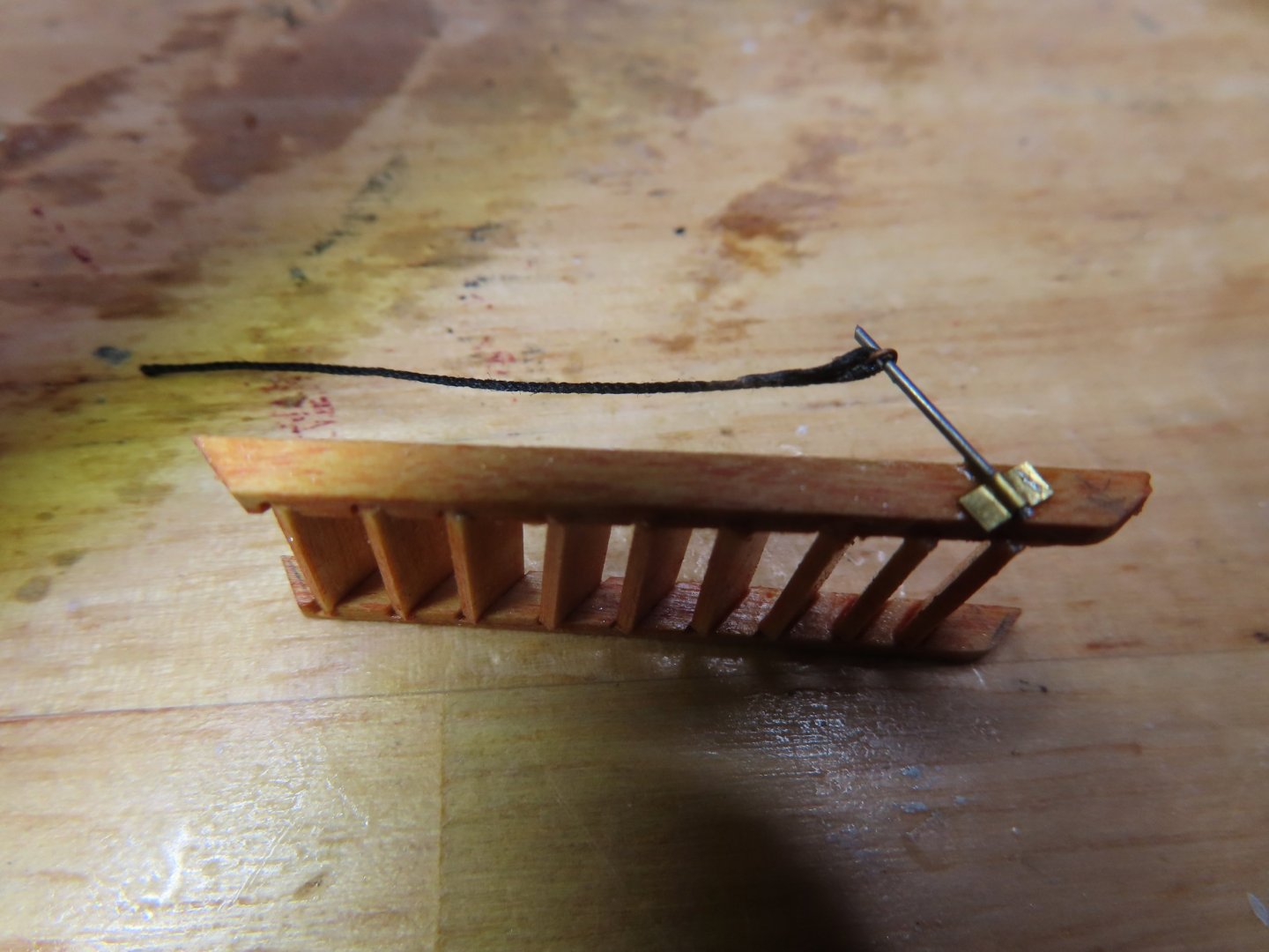
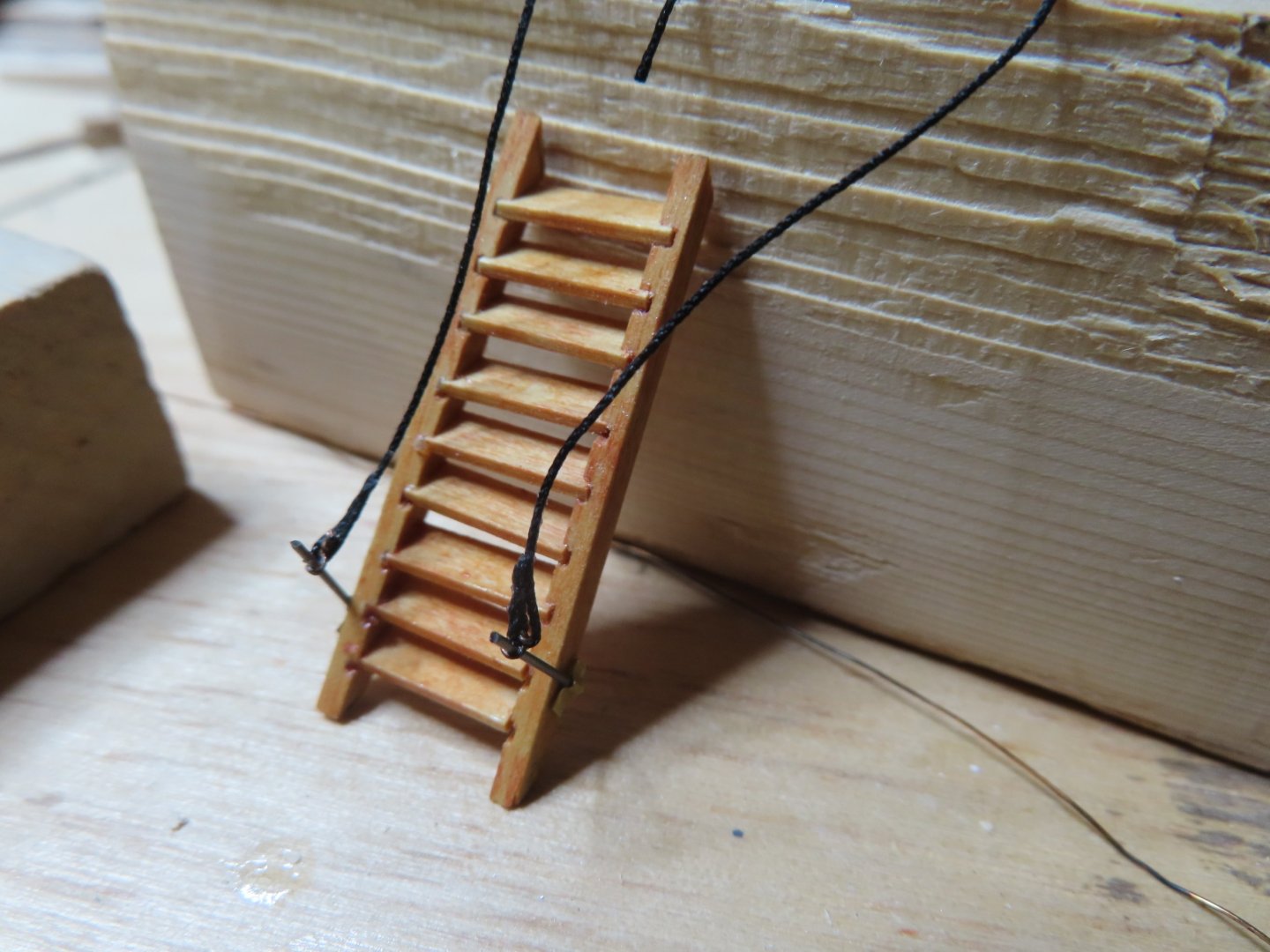
 I ran into a problem with the ladders for the capstan hatchway. I made them snug to the hatchway walls such that I could not slide the ladder down the hatchway because the stanchions made the ladders too wide. Therefore, I modified the stanchion attachment method. I filed a grove in the ladders’ sides for the stanchions to recess into. In theory this should have been simple, but the execution was not. Just the slightest nudge, on the stanchion and it would pop off the ladder. It took numerous attempts, gnashing teeth, time, and vocabulary that would have gotten me divorced if I had ever been married. But eventually, it got done. The upper ends of the hand ropes were tied off on the brass framework.
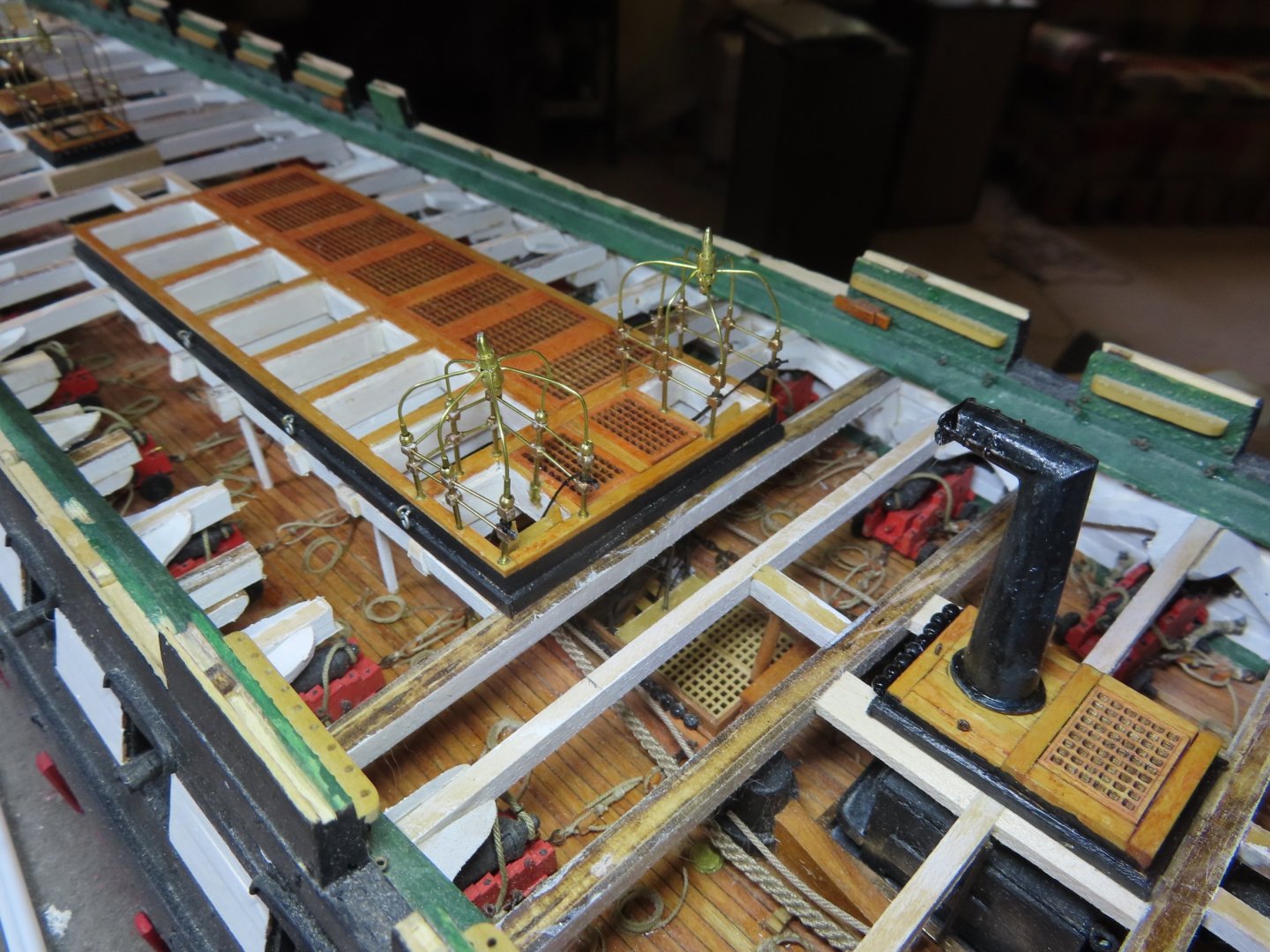
-
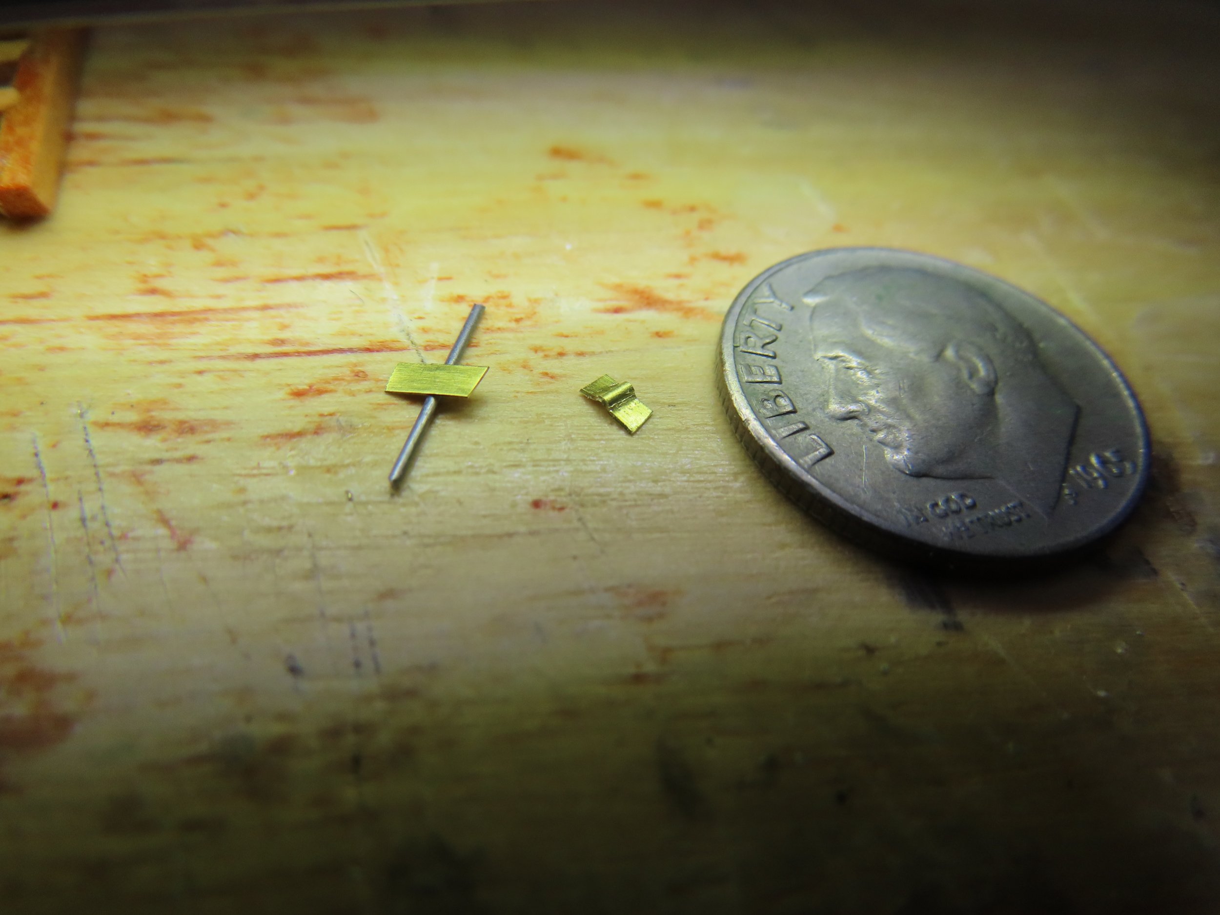
To secure the stanchion to the ladders’ sides, brass brackets were made out of .005” brass sheet cut into a strip and cut to length. These provided sufficient gluing surfaces to secure the stanchions.

-
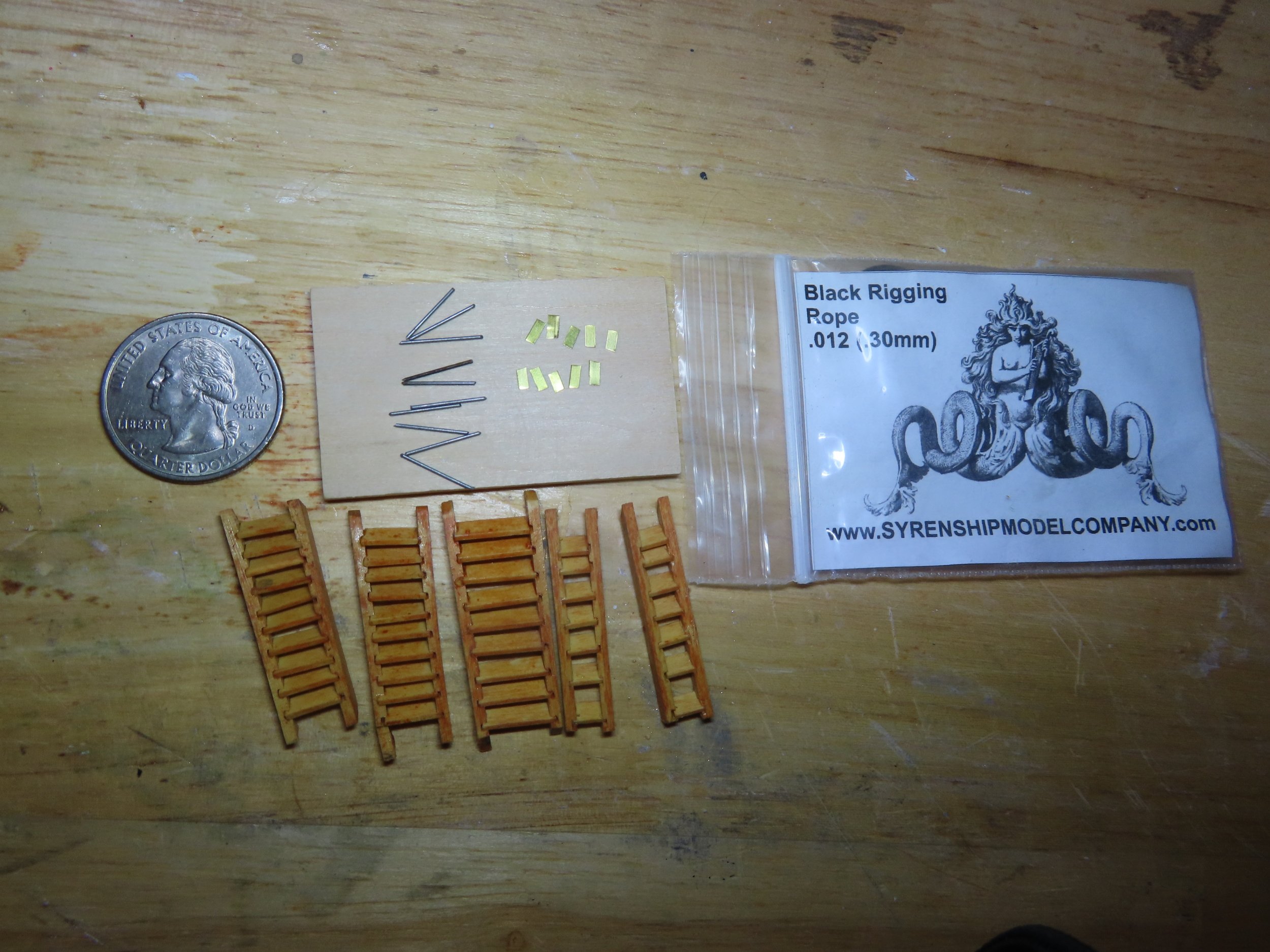
Companionway Ladder Hand Ropes As I mentioned in my last post, I am adding the hand ropes to the companionway ladders going from the spar deck to the gun deck, which were made last year. At the base of the ladders, the stanchions anchor the hand ropes. Trying to maintain close to scale as possible (within reason) with the US Navy plans, I used 0.013” (0.33 mm) music wire cut to 3/8” lengths for the scale stanchions. Additionally, I deduced from the plans that the rope was about 1” diameter or 0.016” scale. Therefore, I used Syren Ship Model Company 0.012” (.30mm) black rope which I had on hand, for the hand rope.

-
Mine should look as good. Well done! Jon
-
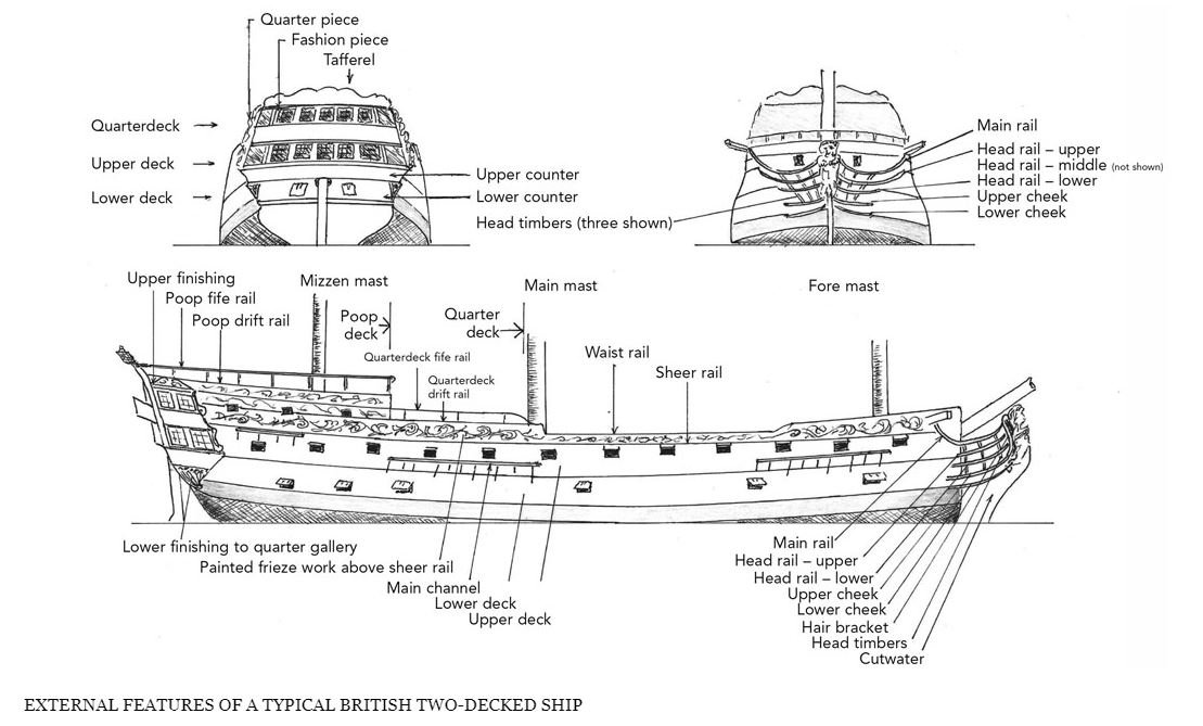
I checked my "library" and found this diagram. I hope this helps. Jon
-
Gregg, your US Navy plan shows the plan view of some of the rails. What I was looking for was elevation and detail views. According to the BlueJacket's instruction booklet (yes, I've got a copy of that, no less a signed copy by the author Laurence Arnot himself!) Page 46 which states, "When CONSTITUTION's bowheads were restored as described, there were no plans and each component had to be templated in place on the ship." I would assume those templates would have been recorded somewhere, but they have not been made public to the best of my knowledge. Jon
-
I struggled with the headrails like everyone else. And it's disappointing and shocking, just shocking that I do not have any US Navy plans showing their dimensions and believe me, I looked for them. I resorted to using the method shown in Hunt's practicum to fabricate them. Sorry to disappoint all of you. Jon
-
Doesn't matter the score. You are the Captain of your ship. What you say, goes! Aye Aye Sir! Jon
-
Short answer: I haven't a clue. To be honest, I don't care how long the blog or a book is, if the the reading/information is enjoyable, it's not too long. I agree with Mustafa. From the Marquardt book picture you posted, that looks to me like a 90 degree twist. I believe I twisted mine although there may be some I didn't. I try with in reason to be as faithful to the actual item as I can make it. I don't remember breaking any hooks getting it to twist. Brass is quite malleable. Of course if you work it too much, it will break from metal fatigue. I did however, break a few from poor drilling or lost a few in my hungry rug. Jon
-
Per your PM that you have officially started your Constitution saga, I am honored to join you and the rest of our group as a follower and look forward to your next postings. Jon
-
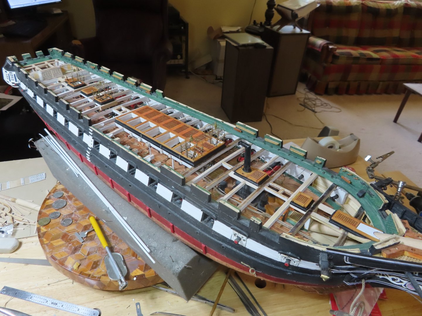
Right now I'm adding the ladders and their rope railings that go through the hatchways that are covered by the brass frameworks. It turned out to be a little tricker than I thought it would be due to the tight tolerances between the openings and the ladders. Once those are completed, I've got the ship's wheels and binnacles to fabricate and install as well as the brass railing around the skylight. I'm going to try to leave off as much planking as I can so that the gun deck can be visible (more or less). My personal philosophy is to have viewers see more the longer they look. For instance, there is a lot of stuff I fabricated for the gun deck that is not clearly visible at first glance. If the viewers move around and spend a little time studying the model, hopefully they will discover new items they weren't initial aware of. I don't want them to become bored. Although I am building my model in the style of the 2017 restoration, the carronades will all be 1812 style. Presently, the actual ship has only two (I believe) 1812 style guns. It has been discussed before that the carronades with the wedge (used for adjusting elevation) are incorrect for the 1812 period. These replica non-working guns were installed during the 1927 restoration. I decided to correct that error and to replace all of them with the 1812 versions (screw type adjusting elevation). I will discuss that process in more detail when I get to them. Jon
-
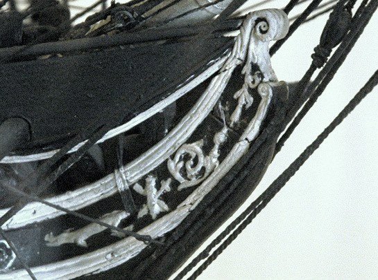
Here are some pictures of the Isaac Hull model with the same trailboard as you are working on. Does this help you any? Jon

-
Just found your build today. Wow, I did not know how challenging working with a solid hull was. I am building the Model Shipways version styled to the 2017 restoration with a scratch built gun deck. I'm one of the slower builders as I have been at it for 8 years and am still working on the hull. I'm just beginning the spar deck. You have a wonderful group of active Conny builders at your disposal should you require assistance. Like you, I live in South Carolina about 75 miles south of you. I'll be looking forward to your future posts. Jon
-
That looks like your standard ready for battle setup: the gun is pull through the gun port, the tackle is loose, and not coiled. Jon
-
First off, I'm not nautical expert, have no military experience (except army ROTC), let alone any naval experience. What I know is from model builders I've followed on various sites and books. So my two cents: As near as I understand it, if the guns are rigged for sea voyage but not battle, the tackle and guns are rigged fast so as to not move or be in the way of the sailor's activities, the gun is pulled up to the bulwark and the gun port is closed and the loose ends of tackle are made snug against the guns. When the guns ae on display for the public or inspection, the guns are pulled through the open gun ports and the loose rope may be coiled "pretty" or remain snug to the gun. If the guns are posed "ready for battle," everything is loose so the gun can recoil freely and the tackle can be manned for loading and pulling back through the gun port. In other words, it all depends on how you want your model to look. Jon
-
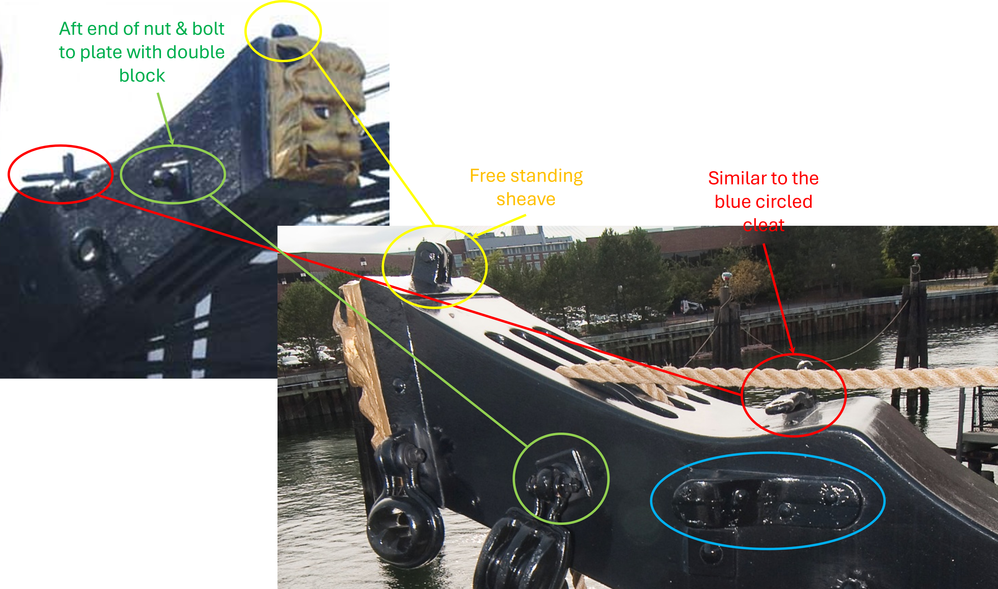
I would never have thought of using fishhooks to create eyebolts; it's a great idea. You did a great job especially at your smaller scale. I'm curious, did the BJ kit provide a cathead face sculpture for the end of the cathead? I didn't see you address this item. If BJ didn't and you can't fabricate one, check online to see if you can buy something. As a last resort, you could just paint the flat end with gold paint. At a foot away, I don't think many would even notice it's a flat surface. Jon
-
Your canopy netting is a beautiful piece of craftsmanship. Did you mention anywhere what material you used for the the actual netting? In the past when I needed netting, I used Tulle, but that does not look like what you used. Your netting has more realistic square openings. Any chance you remember what you used and where you got it? Jon
-
I used an 1/32" eyebolt for than and skipped half cleat thing on the top as well as too small to fabricate. Jon
-
This may help

-
Don't forget the other two photos I sent of the aft side of the cathead which shows additional hardware. Jon
-
USS Constitution by mtbediz - 1:76
JSGerson replied to mtbediz's topic in - Build logs for subjects built 1751 - 1800
This what I wrote when I installed them on my model. Here are some pictures that might help Jon


-
USS Constitution by mtbediz - 1:76
JSGerson replied to mtbediz's topic in - Build logs for subjects built 1751 - 1800
Nice pictures! Jon -
I loved the detail you put into your description and images of how and why you did what you did. This was not easy by any means, and I admire your skills to pull this off. My hat is off to you!!! Jon
- 233 replies
-
- 2
-

-

-
- Model Shipways
- constitution
- (and 5 more)
-
USS Constitution by mtbediz - 1:76
JSGerson replied to mtbediz's topic in - Build logs for subjects built 1751 - 1800
Not the easiest component to construct, but you did it well. BTW, don't forget to complete the hawsers on the port side. Just something I noticed in the last photo. Jon -
USS Constitution by mtbediz - 1:76
JSGerson replied to mtbediz's topic in - Build logs for subjects built 1751 - 1800
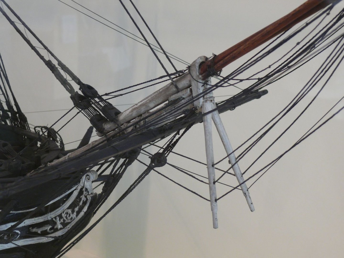
I had a simple choice for the bow bumpkin, the actual ship has it, therefore I have on my model. Whether the model is being rigged for sails or not is immaterial for me, it's there now on the real ship, so it's on my model. And, it was not difficult to install. I still haven't added the stern ones yet. Jon