


JSGerson
-
Posts
2,170 -
Joined
-
Last visited
Content Type
Profiles
Forums
Gallery
Events
Posts posted by JSGerson
-
-
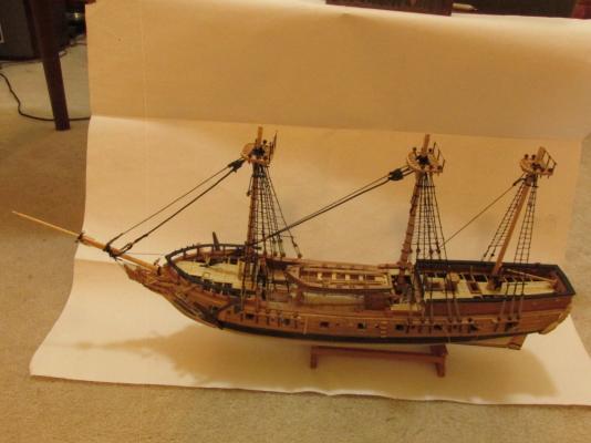
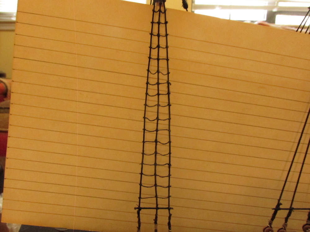
Finally, the initial parts of the lower level ratlines are complete.


- DocBlake, Salty Sea Dog, KenW and 5 others
-
 8
8
-
You lucky stiff! I met Chuck at the last NRG Conference in St. Louis when he demonstrated how he makes his wonderful miniature rope. What surprised most of us who witnessed the demonstration, was that he used the simple Model Expo wooden rope walk (as opposed to the Byrnes precision machined rope walk). He did modify it so that it accepts an electric drill to power it instead of a hand crank. He was willing to answer any and all questions and talk with you. Awfully nice guy.
Unfortunately for me, there is no modelling club near me to help me along.
Jon
-
How did you even know to order the capstan kit if Chuck hasn't yet built one himself let alone advertise it?
Jon
-
Ahh, that makes more sense. Didn't think to check if Harold Hahn had USS Constitution Plans. I have his Rattlesnake plans.
-
Blue Pilot - I too plan on building the Connie and also have the Hunt Practicum, the US Naval History Heritage CD, and a ton of images of the ship, but what are the Hawnn Plan?
-
-
Martin - I did actual use paper clip gauges although you wouldn't know it from my results. I did everything you described...almost. The problem was that I liked seizing the deadeyes on my sizing machine. I could make them nice and tight. I would seize the first deadeye on the machine. Then holding it in place with the gauge on the model, loop the shroud over the mast to the other deadeye also attached to a gauge. A clip was placed on the looped 2nd deadeye to hold the shroud in position. Here is were it got squirrely. I removed the shroud from the model and seized the second end on the machine. I imagine due to the variances in tension, how it looped over the mast the second time in comparison to the first time, placing it on the seizing machine, etc. when finally installing the shroud, things didn't line up as intended. The deadeyes were all seized and glued at this point so I ended up with what I had. I did the best I could with the lashings.
My original concern was I could not seize the shrouds insitu on the model and make it clean and tight. Well I got got clean and tight, but uneven deadeyes. I'll try your method on the next mast step.
Jon
-
If I had thought about printing the name like you did, I don't know if I would have done the lettering the way I did (on a plaque). Either way works. Nice job on the capstan.
Jon
-
Your transom is coming along just fine.
I had a lot of plans for the transom, and had to compromise on just about all of them.
Welcome to the club. I had all kinds of problems with the back end of the model and had to get creative in order to get the ship's name on her. Yours came very nice. Can I assume you used dry transfer lettering?
Your window frames look great also. Can you provide any detail as to how you accomplished it?
-
I just discovered your "new" build log today. New for me but you've started it back in March. I was wondering if you were aware of the work of Gene Bodnar at Model Ship Builder who built not one, but three cross sections of the Connie (1:32 scale) which could be put together to form the complete hull? If not take a look at his build log.
BTW nice work on this build too.
-
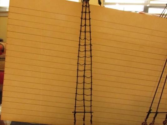
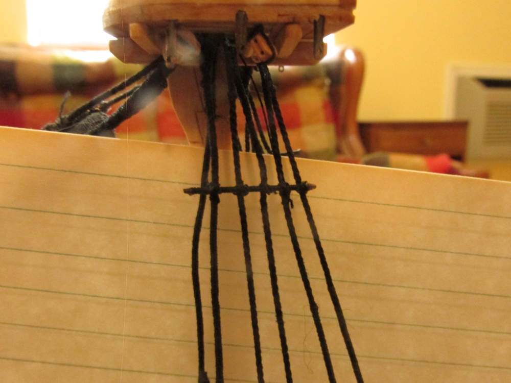
Once I was satisfied all was right with the world, a drop of CA glue was applied to each knot and the excess lines cut off, not with a scissors, but with a sharp X-acto knife to get as close to the knot as possible. It may not be the best ratline ever done, but hopefully it’s not too bad for my first.
-
-
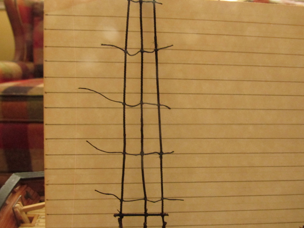
Ratlines
All the staves were installed under the tops and above the deadeyes. The ones above the deadeyes gave me pause. Due to lack of my skill and/or experience the deadeyes did not line up was well as I had hoped. I was consoled somewhat because I had read somewhere that they did not always lined up due to the need to be adjusted due to wind conditions, moisture, etc. which affect their tautness. Therefore I attempted to minimize the obviousness of their irregularity by installing the lower staves a little higher above the deadeyes. After taking two weeks off from model building to visit Mom in Florida (she turns 97 next week) I returned home and realized that after looking at the model afresh, I could have lowered them a bit more but they were glued into place. Be that as it may, I plodded on. Per Mr. Antscherl’s instructions I started to install the ratlines using my thinnest cotton thread. Using an index card with the proper spacing of the ratlines laid out, I installed a line every third row without any glue so as to maintain the shrouds vertical straightness. A simple knot was used on the outside shrouds and Clove Hitch knots were used on the interior shrouds. Because they were not glued at this point, final line adjustments could be made.

- Martin W and CaptainSteve
-
2
-
Very nicely done. You are a better man than me. I'll be very happy just to get the standing rigging in place. Just out of curiosity since I won't be adding sails to my model, what kind of sail cloth are you using and why?
-
I was so new to model ship building at this point, I didn't quite understand what I was doing so was following the instructions blind. If you haven't already, I would suggest not cutting the top of the frames off. Hahn's plans are designed for the model to be built upside down with the top of the frames fitting into a jig. Therefore there is extra frame that needs to be cut off. If you know exactly what you are doing and are precise in cutting to exact length, it should work. If not, leaving excess frame to be cut latter while on the model give you a bit more leeway. The extra frame wood will also allow you to align the pseudo frames easier.
In my case I had difficulty because I didn't understand what I was doing. I had never seen a wooden boat put together before at this detail level. Some of my resulting frames were too short, tilted at the wrong angle, etc. even though I thought I was cutting as precise as I could be. It is only latter that I understood the process and then it was too late in some areas.
As for mistakes in the practicum, there are a number of them, most of which I have documented when I caught them. In the later chapters they get more numerous. If you have looked at the later chapters, you will notice there is not one photo of a completed model. That is because Mr. Hunt never completed it but just showed how things needed to be done...for the most part. He stated somewhere that he was building 4 kits at once and was on a deadline. It appears that he had to cut corners.
-
Well then, it still looks like you have everything under control, probably more control than I did at that stage. You're doing good.
-
Based on what I can see in your photo, your gun port looks right. When I made these, my skills weren't the best so some of my port lips aren't exact. But at this scale, unless you look real close with a magnifying glass the variations vanish (at least with my eyes).
You may want to prepare the gun ports for the port lids at this point. The upper frame of the ports needs to be notched to accept the lid hinges The hinges are the only gluing surface you have to attach the lids to the ports and they don't provide much surface area for glue. I have already knocked half of them off since. I used CA glue, but if I were to do it again, I think epoxy might be a better choice. You may even want to postpone their attachment to a later time when they are less prone to be hit..
Nice job so far
Jon
-
From my experience, whatever pitfalls the model kit doesn't have, I make myself
 !!
!!BTY, the transom looks real good. Nice job.
-
-
The transom gave me problems. Bob ended up with 5 planks because it appears I may have chopped too much off the stern so I ended up with 4 planks. I thought I followed Hunt's instructions to the letter (as well as I understood it). How I messed up I don't know, but my stern was too short. Therefore there were repercussions down the road. I had to squeeze the rudder post into position, make adjustments to the deck were it protruded as well as adjust the "horse" behind the tiller.
To be honest, I don't remember exactly what I did to ensure the plywood and framing that made up the transom, adhered solidly to the deck (it was 6 years ago - Have I been working on this for that long?), But looking at my photos, it looks like I was lavish with the glue knowing that this part of the construction would be covered up and that the side planking would eventually provide full strength. I don't think I pinned in place or I would have mentioned that in the log.
You can see my initial progress on the transom and the problems I had.
Part 1 Post #10
Part 2 Post #24
Part 3 Post #38
All I can say is be very careful here.
Jon
-
I'll be curious as to how you'll handle the ebony. I've never worked with it before and I understand it is tough wood to work with especially bending. In my case I stained some walnut to get the effect.
-
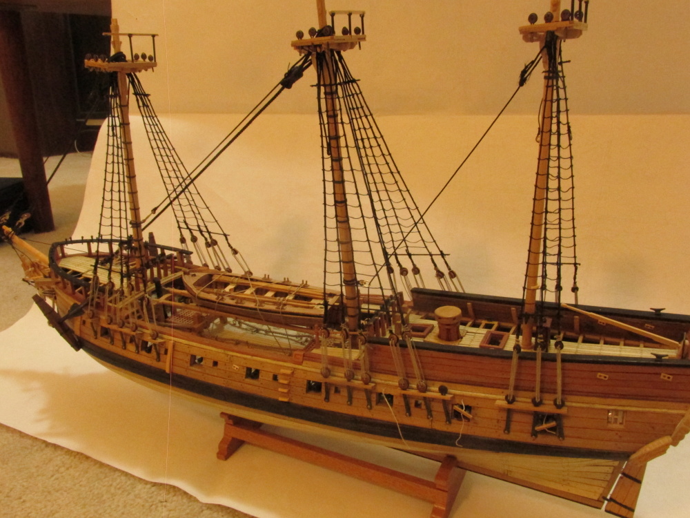
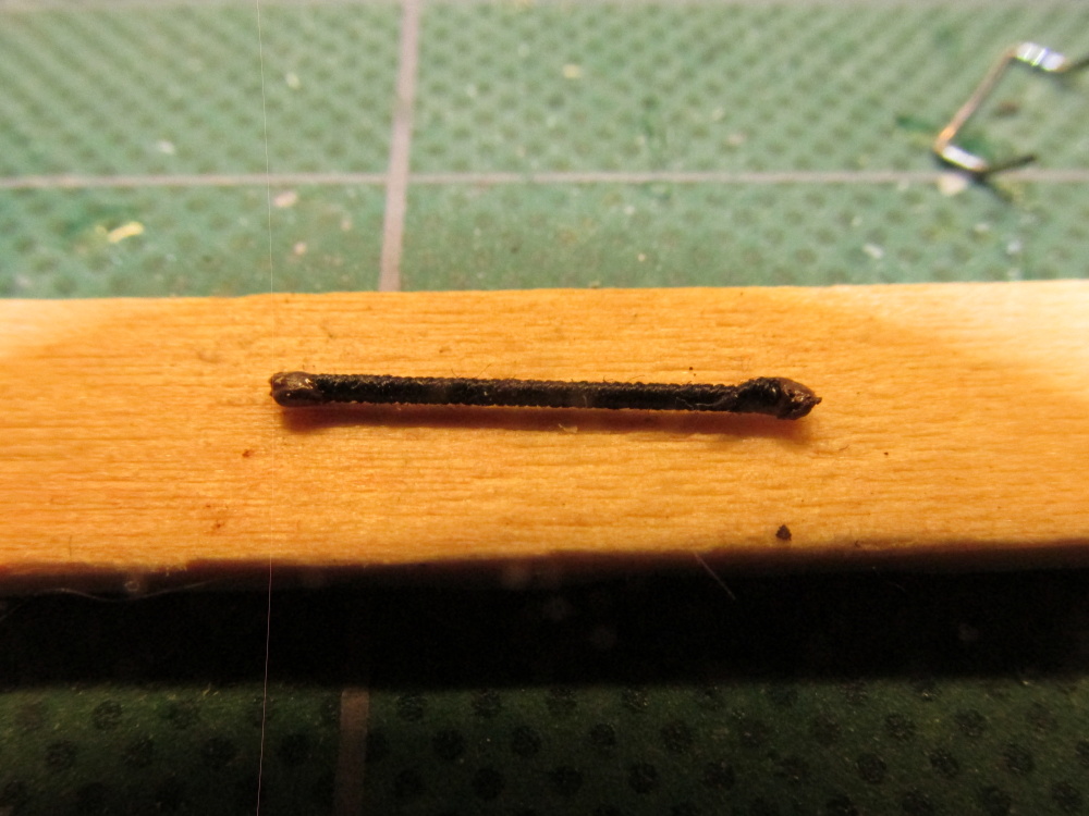
Once the proper length was served, it was cut off from the rest of the wire and the two ends were dipped into some brown paint to represent the leather caps (not that you could actually see them) and lashed to the shrouds. There are still some fuzzys that still have to be snipped off.


-
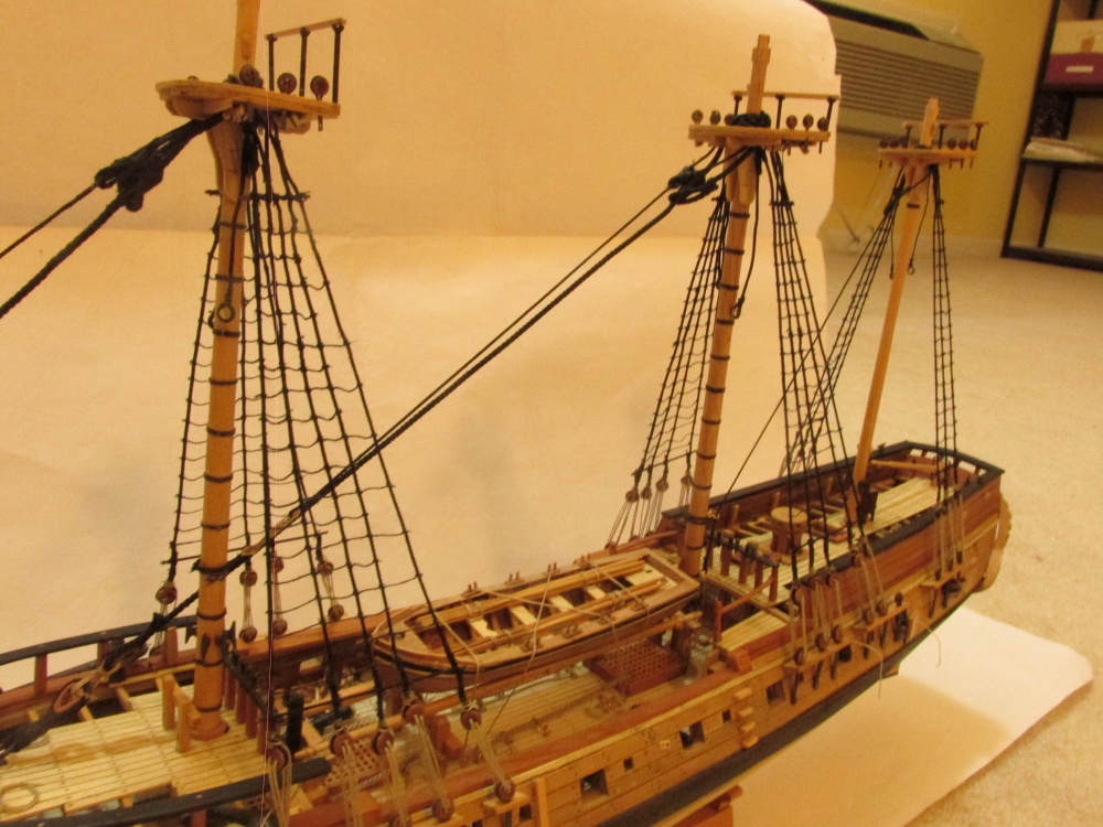
Ratlines – Futtock Staves
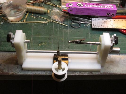
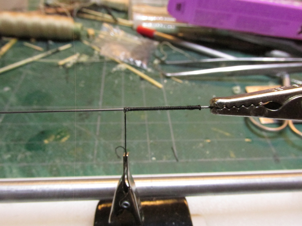
Following David Antscherl, the next activity is the ratlines. In order to do them the Futtock Staves need to be installed first. According to Antscherl the stave was served rope. According to James Lees’ The Masting and Rigging of English Ships of War 1625-1860 an iron bar was used on some ships. David opted to use served bamboo (made with a draw plate the same as tree nails) in lieu of served rope for stiffness because you cannot see the difference. I went a step further, since you cannot see what material was served, why take the trouble to make bamboo staves? I used music wire which is very stiff and it satisfies Lees and follows Antscherl. The model calls for 0.8mm rope so I used 0.02” (0.51mm) music wire which when served should approximate 0.8mm.
My serving machine was able to accommodate the wire and served it easily. The alligator clip in the image is applying tension to the line while some CA glue dries.

- Martin W, CaptainSteve and KenW
-
3
-
I really wasn't suggesting that you make the buckets, but just to look at his technique. You both used the dowel to support the construction. Then again his other stuff looks real neat too.


Rattlesnake by DocBlake - Mamoli - 1/64 scale - Bob Hunt kit-bash log
in - Kit build logs for subjects built from 1751 - 1800
Posted
In Bob Hunt practicum he points you to a company that makes very fine cutting wheels. I bought some and they cut through razor blades like butter, but they are very delicate. Breathe on them wrong and they will shatter. From other sources, people like to use old hack saw blades in lieu of razors for its rigidity. The real trick is figuring a way to manipulate the scraper so that you can cut the profile. Do you hold the blade against a fixed position spinning cutter or move the cutter while the blade is held fixed? The choice is yours.
It is very important that you wear eye protection. You don't want metal shards or broken cutting discs pieces in your eye. Because I am very farsighted and wear tri-focals, I need a clip-on 3X eye loupe as well and have to get within inches of the cutting blade to see what I am doing. Then I had to make numerous trial cuts till I got something halfway decent.
Once you've created the scraper, clamp it in a vise...tight. Use a piece of wood that is longer than you need and fits exactly to the width of the scraper's profile cut you made. Draw the wood strip repeatedly through the scraper.
Jon