


JSGerson
-
Posts
2,482 -
Joined
-
Last visited
Content Type
Profiles
Forums
Gallery
Events
Posts posted by JSGerson
-
-
From the book Rigging Period Ship Models by Lennarth Petersson, I found these diagrams for studding sails. I hope these are what you are looking for.
-
When I wrote the above comment, I did check your log for the construction of the boat but didn't go back far enough. I had forgotten that you indicated that you followed my log in making the boat.
Installing the boat requires that you first install the spare masts to support the boat which need to be lashed down first, and then the boat mounted and tied down on top of those. It's the tying of those lines which will become difficult as you add more rigging that may interfere with that process.
I tried to work from the inside out, bottom to top. The boat is inside bottom.
Jon
-
You make it look so easy!!!
Jon
- Canute, xken and CaptainSteve
-
 3
3
-
The tiller was made from boxwood to resemble the US Navy plans and inserted into the rudder stem where a hole had been previously drilled. An additional hole was added on the rudder where it jets out midway down. A final coat of Minwax Polycrylic was added to the whole model to protect the bare wood and add a little gloss to the painted sections as well. One down, three to go.
- CaptainSteve, xken, DocBlake and 6 others
-
9
-
The rudder was then painted white with two coats, re-enforcing plates added where the tiller is inserted into the rudder stem, added “metal” straps made out of painted card stock, and pins to secure the rudder to the hull.

- CaptainSteve, MEDDO, Duanelaker and 1 other
-
4
-
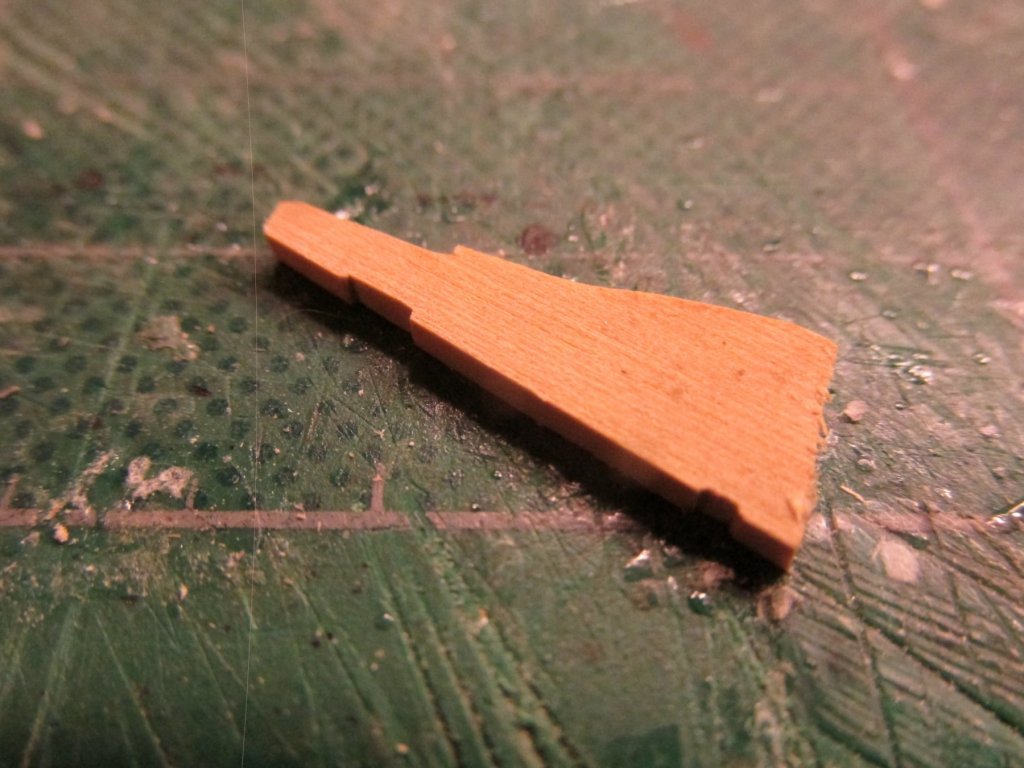
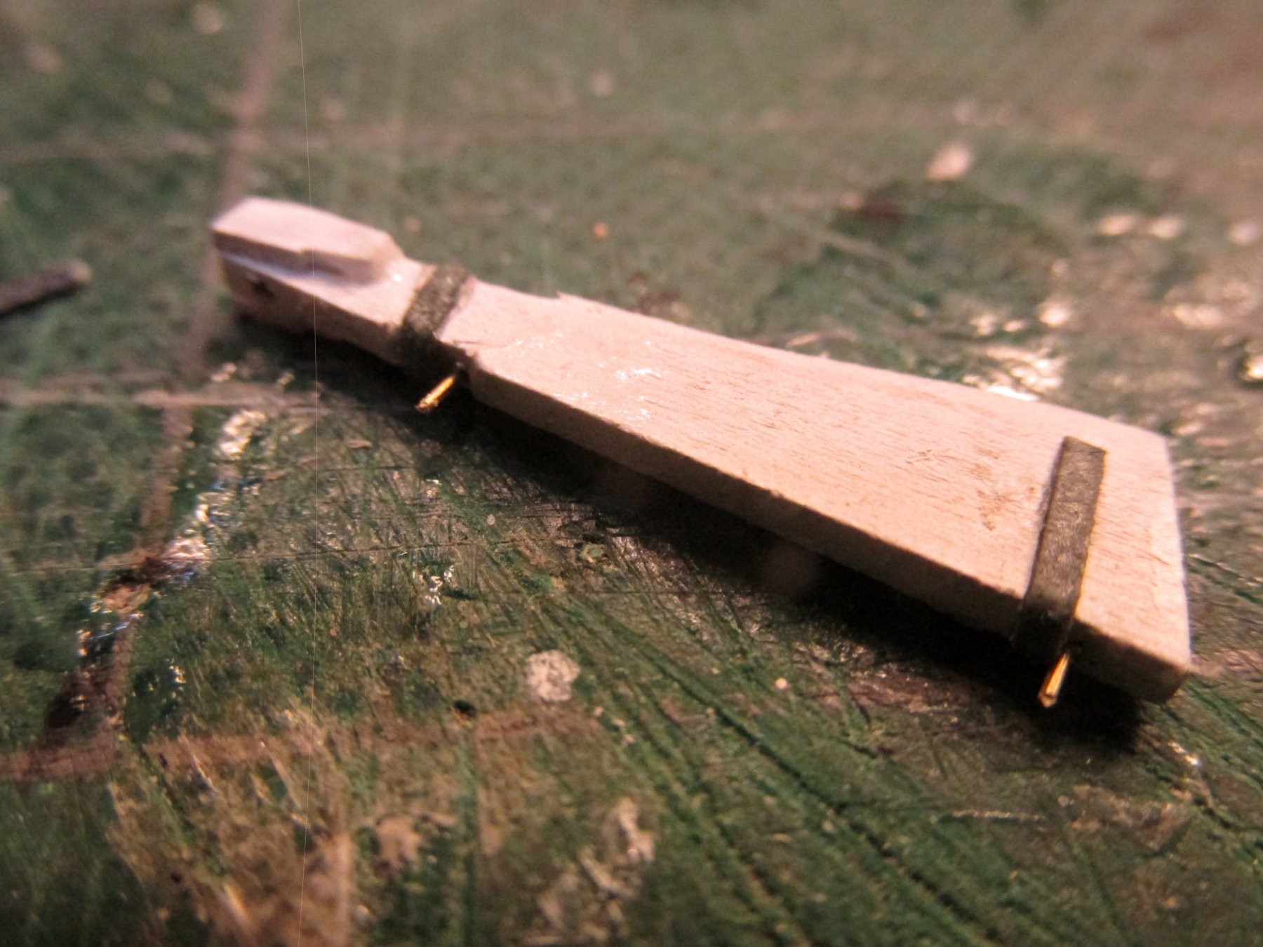
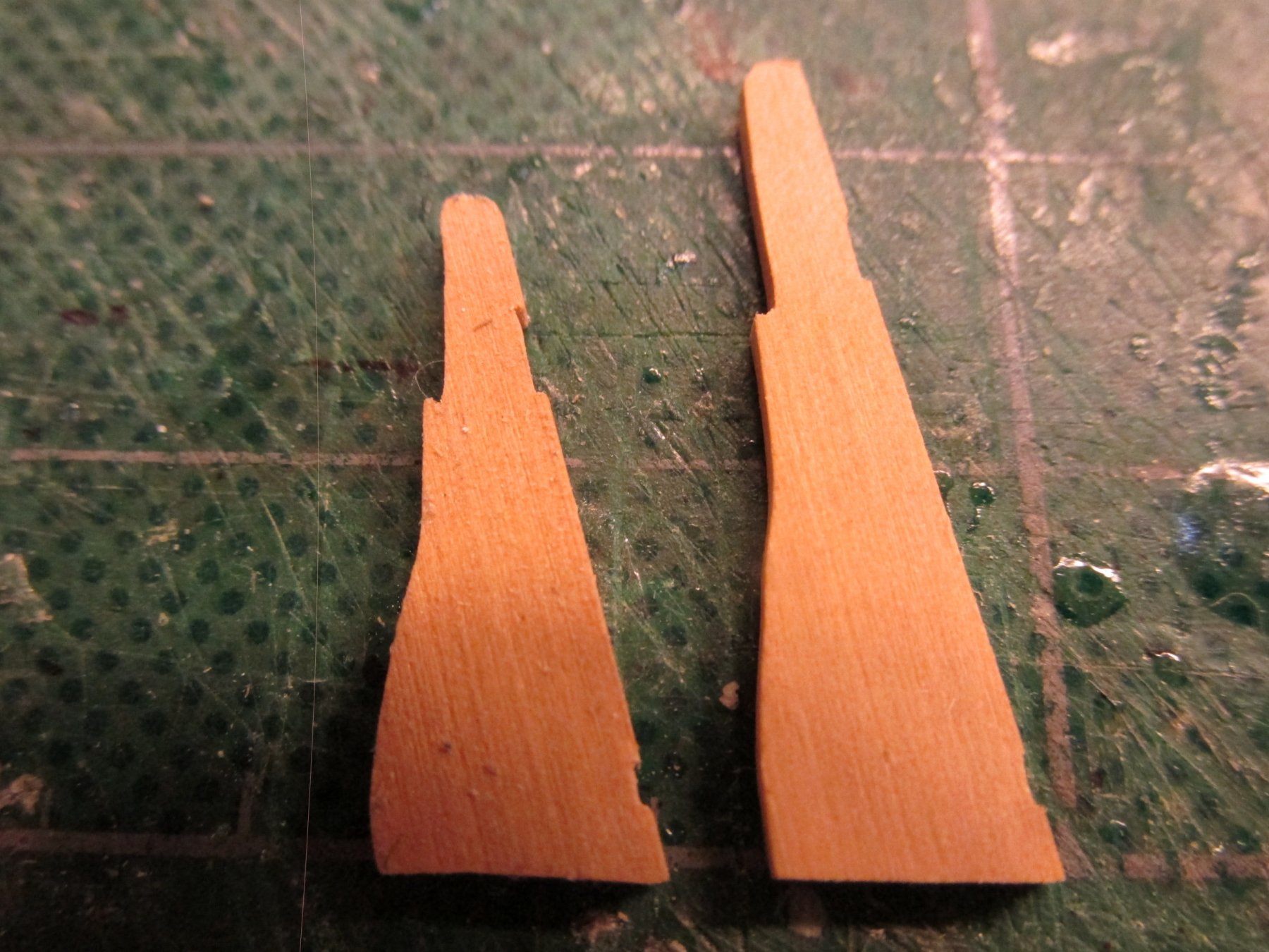
Pinnace Rudder
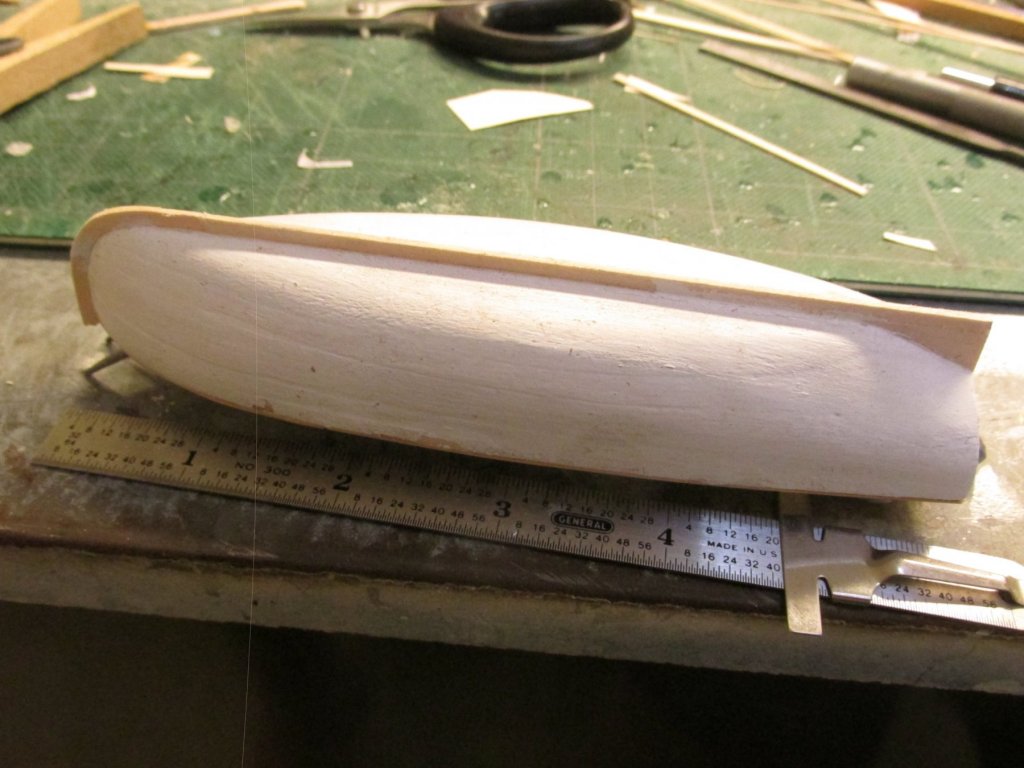
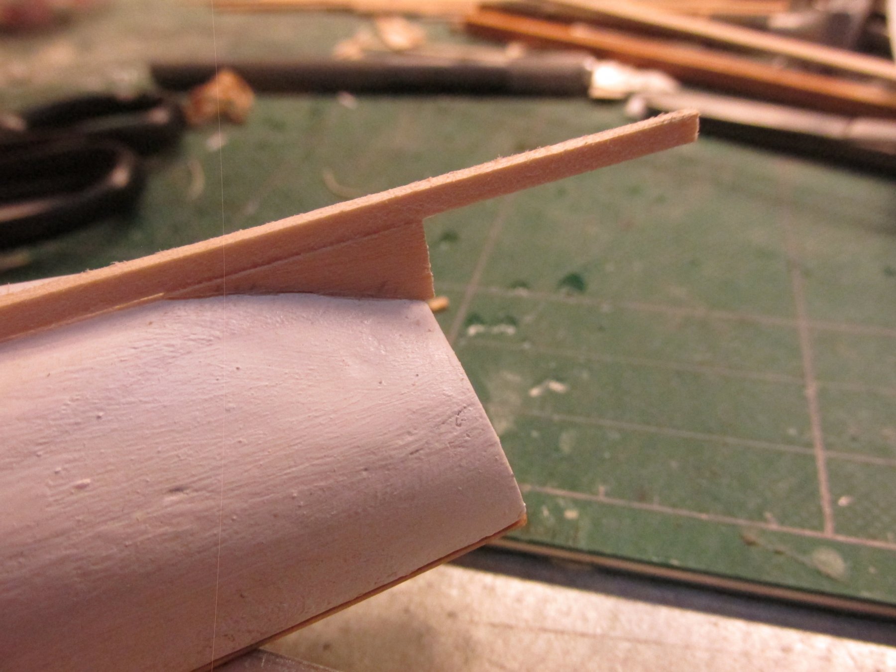
The last major piece of the pinnace is the rudder. As in my previous part fabrications, I made a template from the US Navy plans and cut out the part from some boxwood stock. So far everything was going smooth…too smooth as it turned out. To my surprise, when I placed the newly cutout rudder part next to the stern of the pinnace, something was wrong…very wrong. The part matched exactly the shape and size in the plans as all my other parts had done except in this case IT WAS TOO SMALL for the boat. What was going on?
The length of the boat was correct, so was the width, but not the height. I never measured the height of the hull once it was carved. I never thought to check that dimension since the hull was formed using the pre-cut pieces that made up the bread and butter sandwich method construction. Subconsciously I just assumed the carved hull was correct for outside dimensions. For some reason(s), either accumulative measuring errors, I didn’t remove enough material during the carving process, or whatever, the hull was too tall. I was not about to shelve this little model and start over.
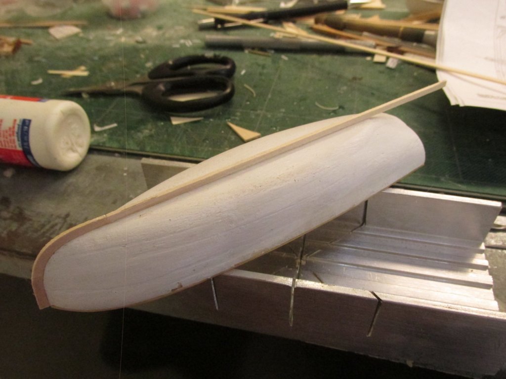
To salvage the model, I decided to just go with it and only I, God, and the readers of this log would know. I got on the computer, brought up the image of the US Nay plan of pinnace (reduced to scale) and stretched the image vertically to reflect the actual build height. That image was printed, a new template was made, and a new part made. In the photo below you can see the difference.

- Tigersteve, Geoff Matson and MEDDO
-
3
-
Beautiful looking model. I noticed that you haven't documented the building of the ship's boat. Have you made it yet?
You might want to think about installing it soon before you have too many lines interfering with a clean installation.
Jon
- Tigersteve, Martin W, EJ_L and 1 other
-
4
-
CA glue was used to adhere the strip to the hull working my way from the bow to the transom for each side. Then the transom fender piece was added.

- Geoff Matson, Tigersteve, coxswain and 3 others
-
6
-
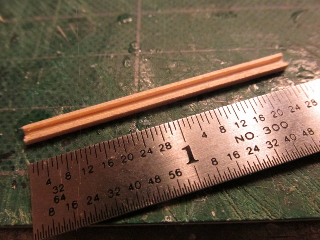
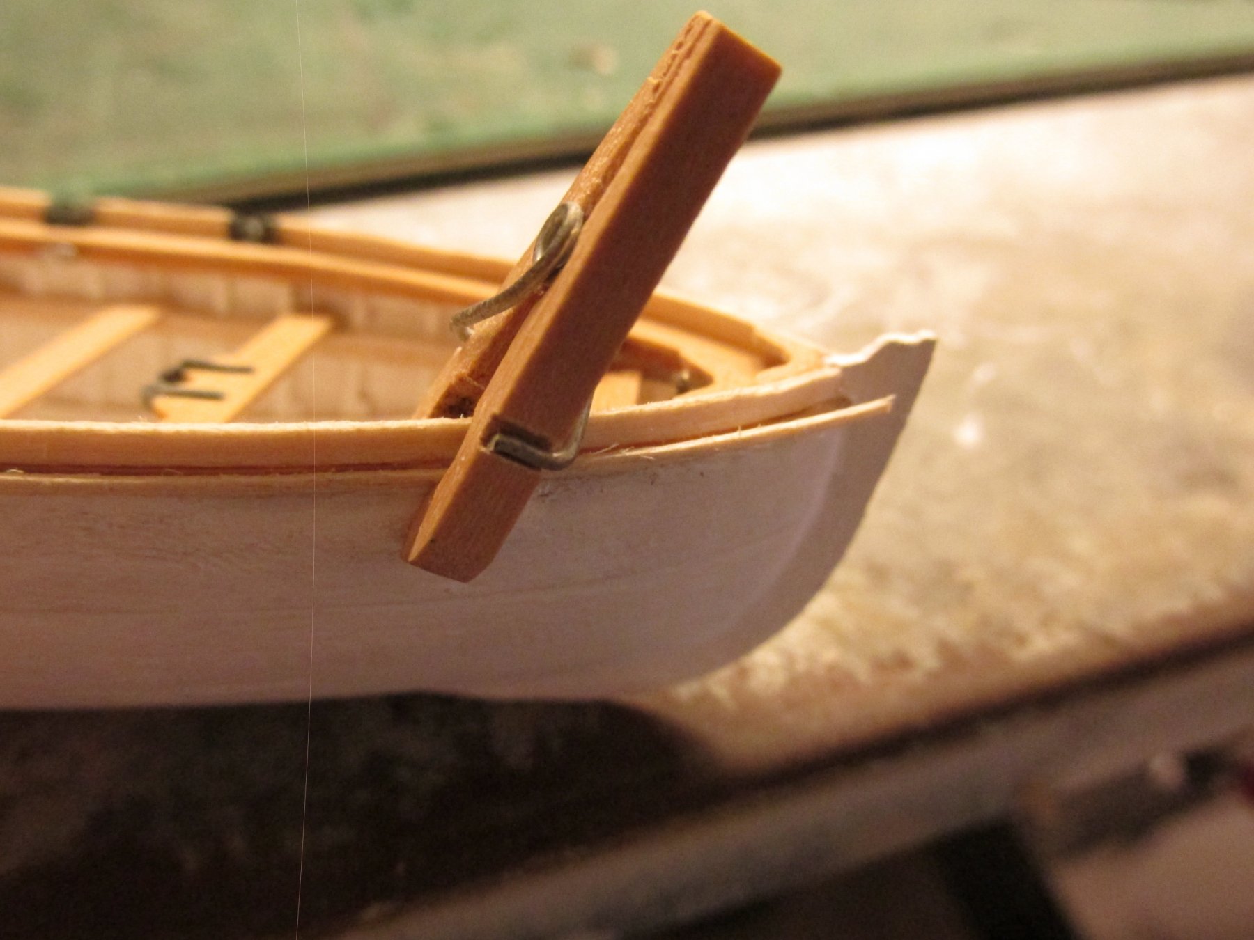
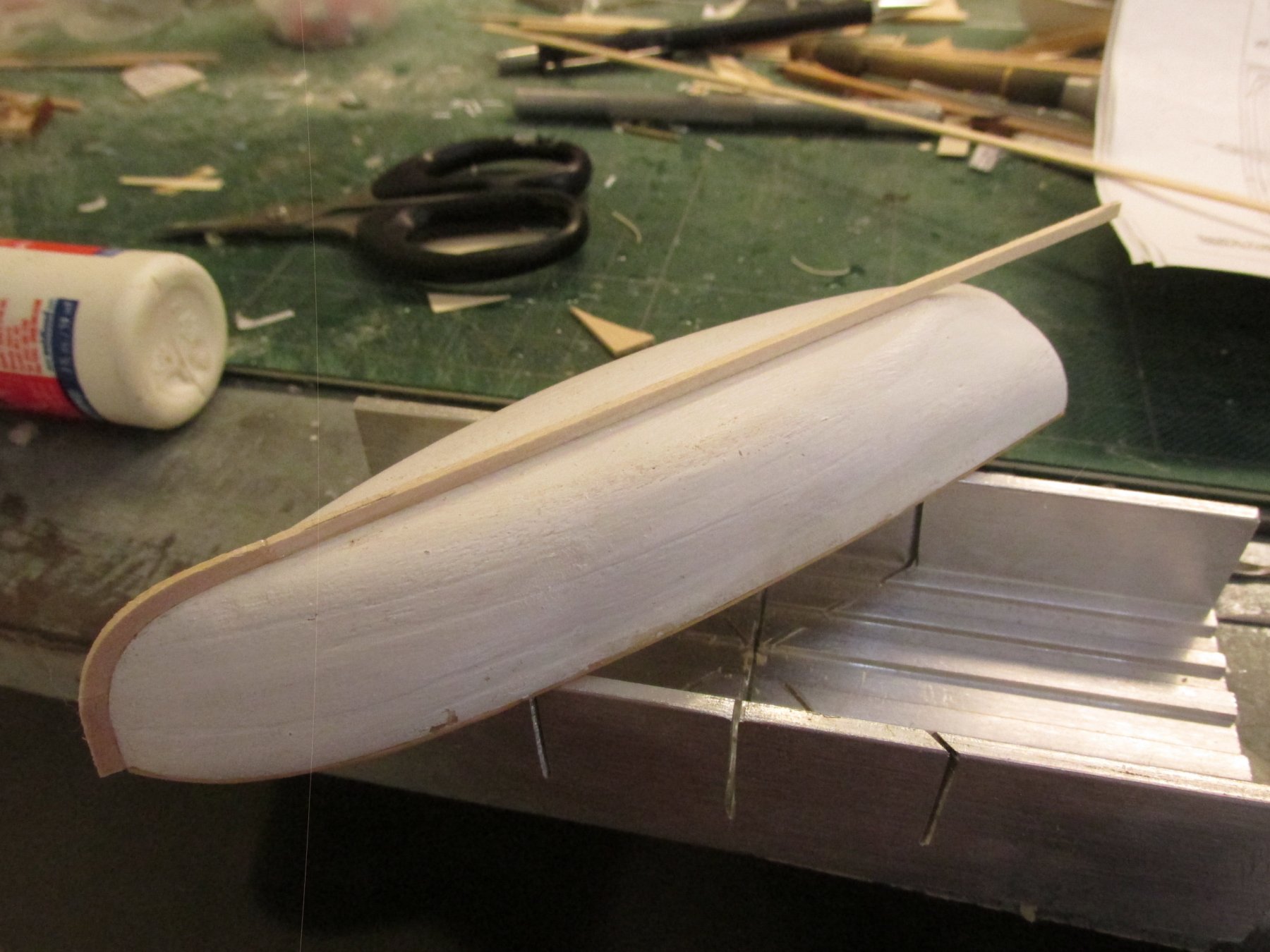
Pinnace Fender
The last thing to install on the hull (excluding the rudder) was the half round fender. Per the US Navy plans, the fender 2½” x 1¼”. This translated to 1/32” x 1/64” at scale which matched the kit’s instructions. Now that is one fragile strip of wood. I chose to use 1/32” x 1/32” because wanted the extra strength as I pulled it through a scraper to create the half-round profile. When I was done, I needed my magnifying headset to actual see the roundness and to be sure I was gluing the proper side to the hull. In other words, nobody but me would know I had even bothered to shape the fender
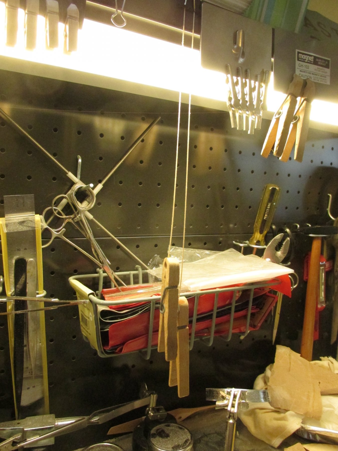
Initially when I was pulling the strips through the scraper, the fine strip would curl 90-degrees towards the scraped side, opposite of what I would have liked. Dipping my fingers in water and pulling the strips through my fingers removed the curl as the water seeped into the wood. To ensure the strips didn’t re-curl as they dried, I hung them with a clothes pin as a weight to keep them straight.

-
-
Thanks for the tip Glen. Unfortunately I thought of the same thing after I had made them all. Hindsight is 20-20 as they say.
I got the razor saw and mitre box at one of the NRG conventions from a company called UMM According to the box, their website is umm-usa.com. I believe Micro-Mark sells the saw; l don't know about the mitre box.
-
I'm in awe!! I have never seen anyone make yards in multiple parts before. That is a nice bit of craftsmanship. Is there a reason you chose to take this route as opposed to making the yards in one piece? Having never made jackstay before, does the rod running the length of the yard pass through a very fine eyebolt?
Jonathan
-
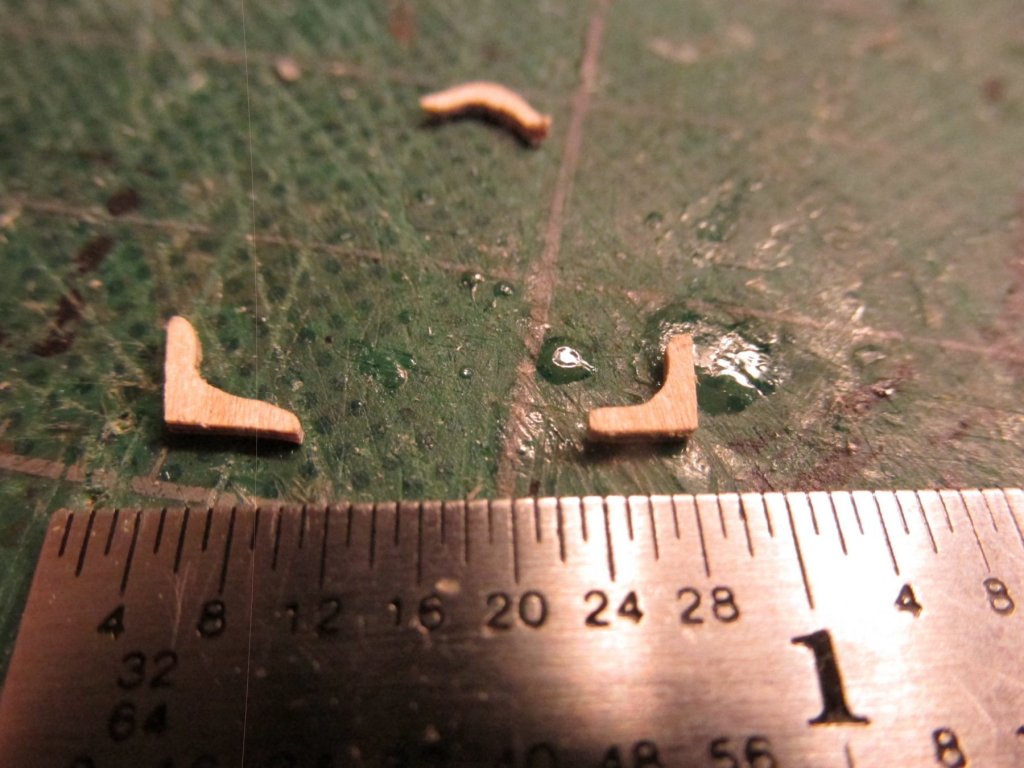
Pinnace Upper Horizontal Knees
The upper horizontal knees were fabricated like the lower ones. After I took the photo of the three knees below, I remade the bow knee because I didn’t like the way it fit.

-
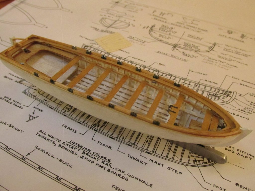
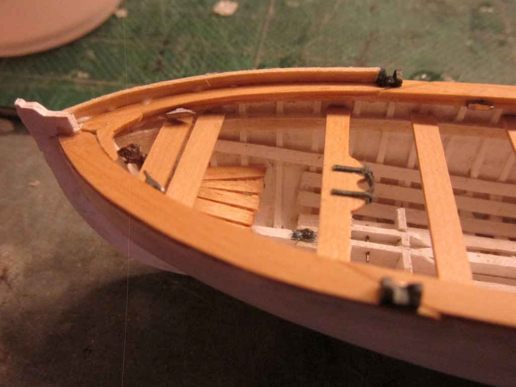
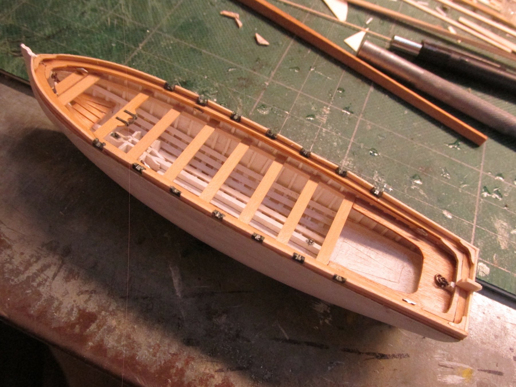
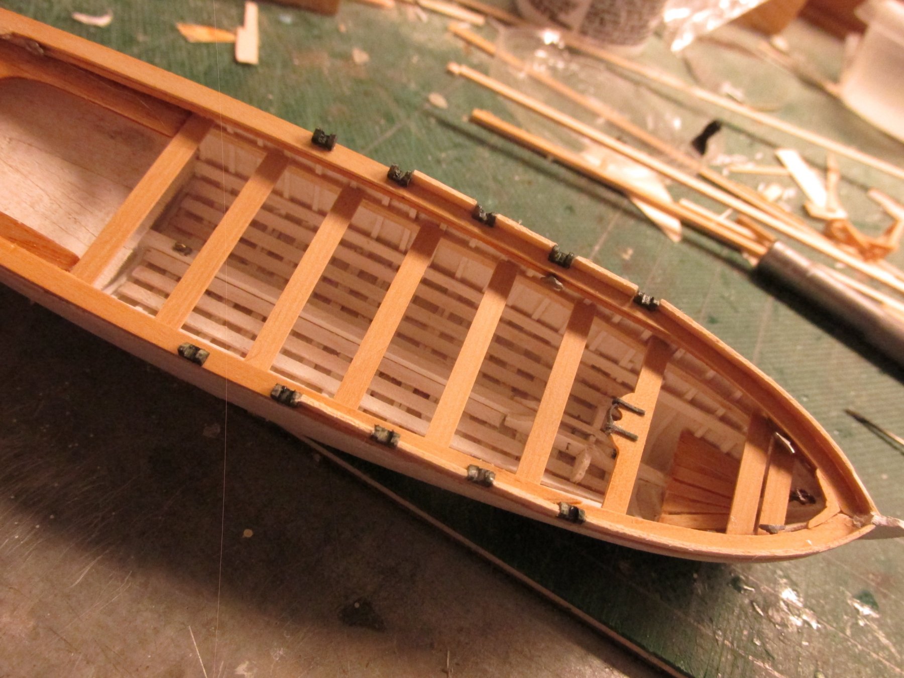
The practicum would have you glue in place the rails with the required spacing to create openings for the rowlocks. Then it would have you custom fit cut styrene flat pieces to create the locks. I did it differently.
Because the rowlock had to be in specific positions, I installed the first set beginning at the bow end. The rails at the bow were pre-bent to the required curve and custom fitted between the stem and the first rowlock. The next set was done the same way; install the lock first, then the rail till the final rail was installed reaching the transom.

- Jack12477, Geoff Matson, Tim Curtis and 6 others
-
9
-
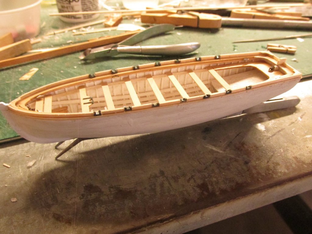
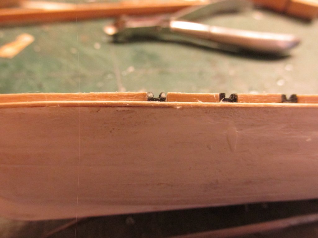
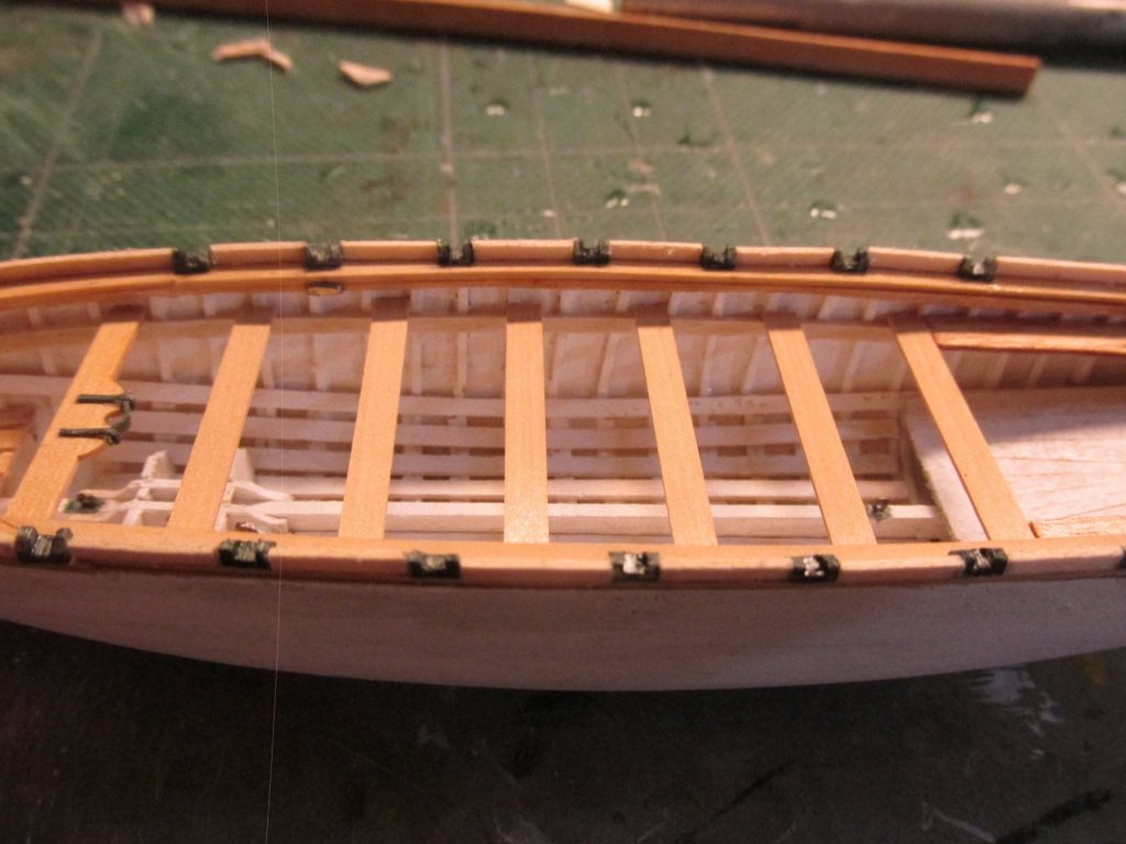
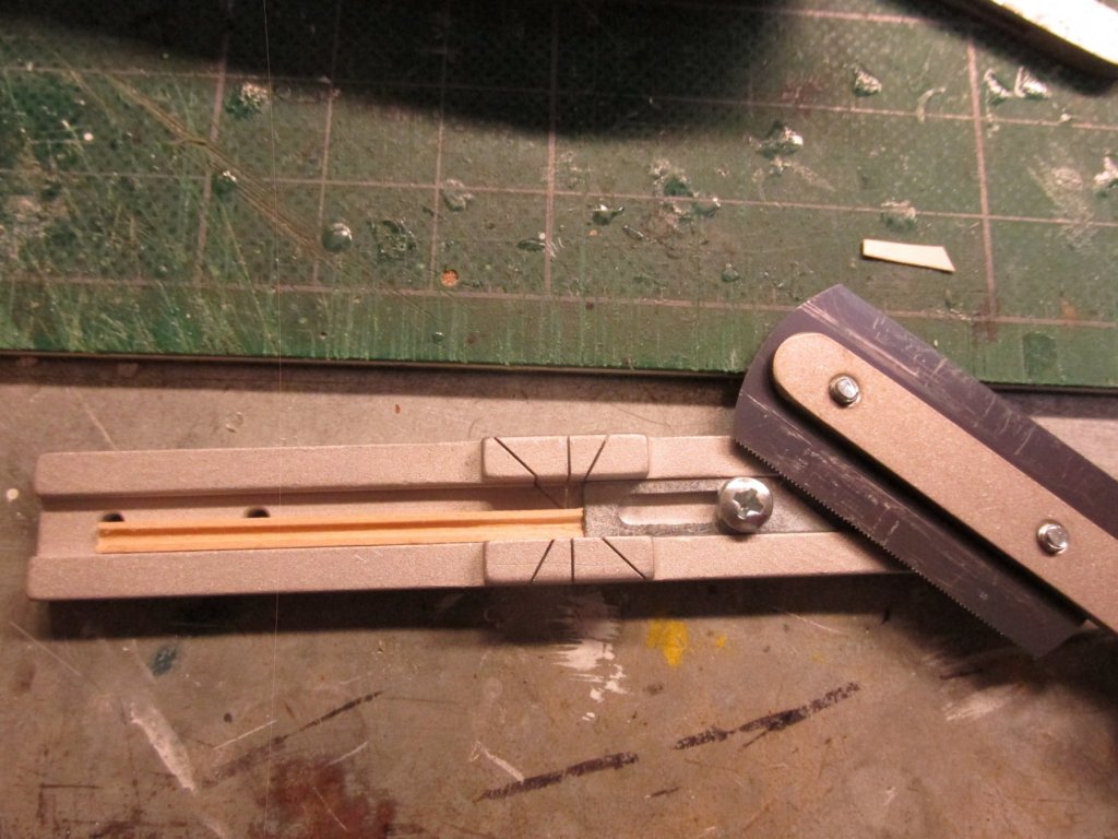
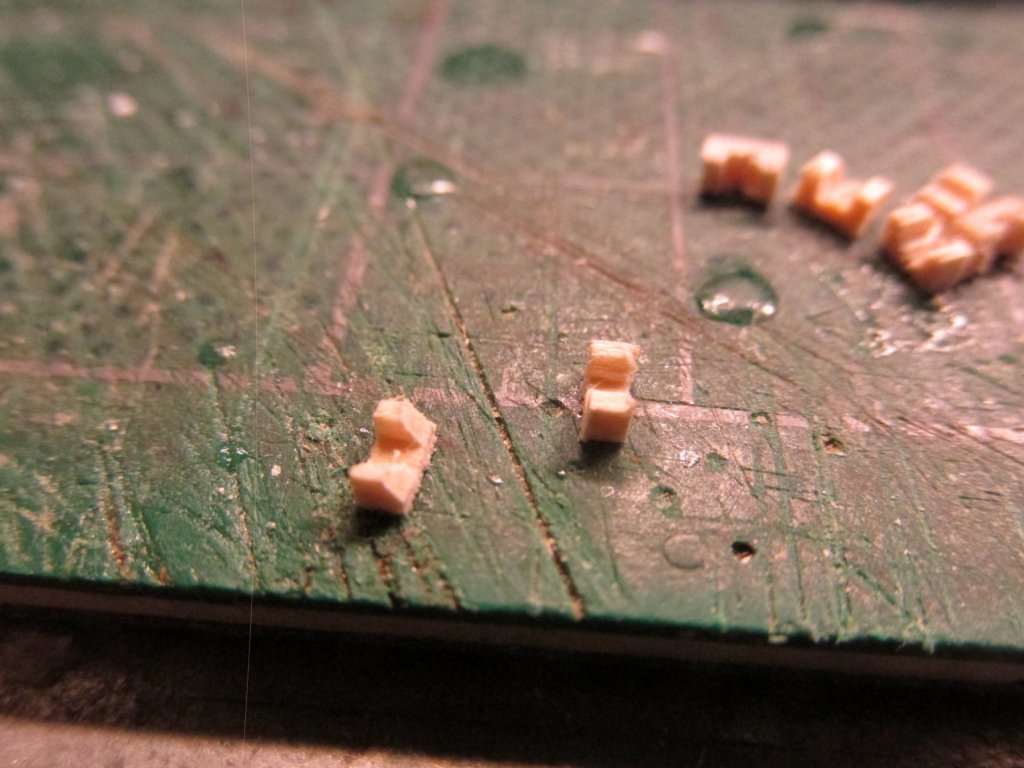
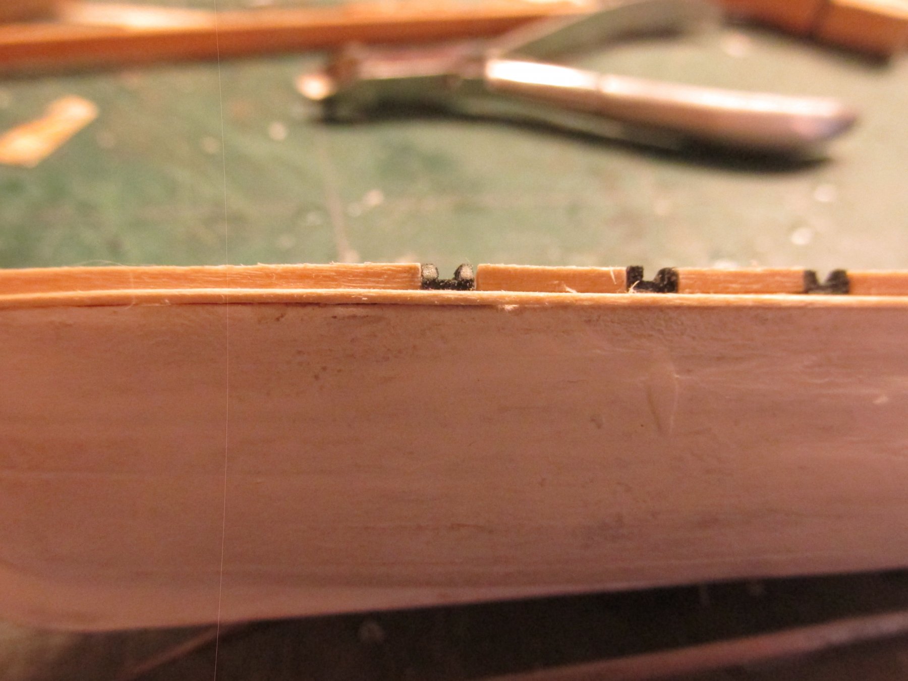
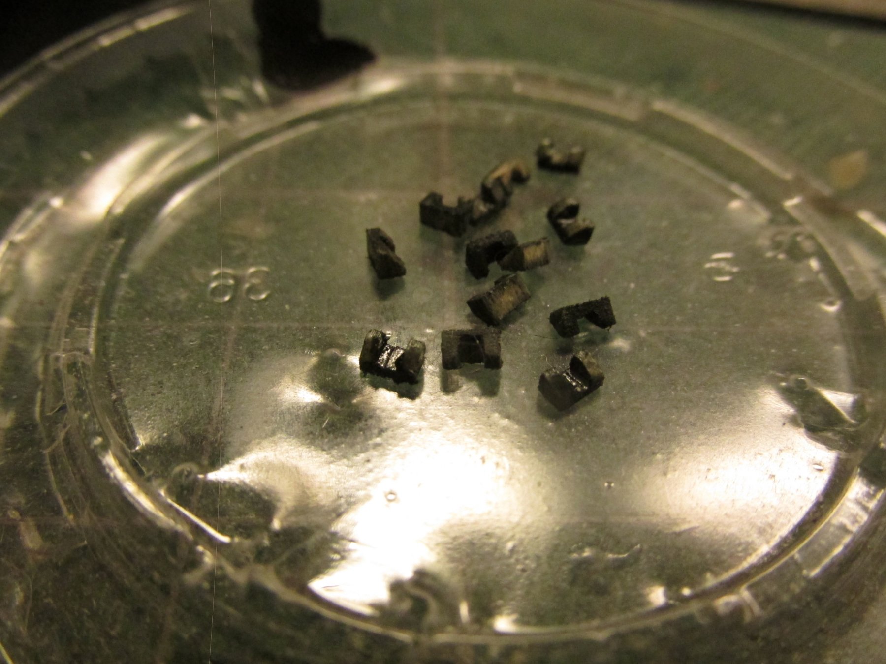
Pinnace Rail and Rowlocks
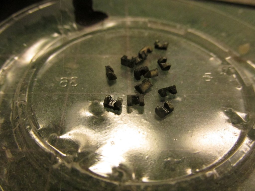
The 14 rowlocks were fabricated from a 1/8” x 1/16” piece of basswood stock to match the rail height of 1/16”. A channel was cut along the length of the stock by making multiple passes with my Byrnes Saw. The piece of channeled wood was then sliced to 3/64” lengths like a loaf of bread with a razor saw and its miter accessory. Then one side was filed to a 45-degree angle to mimic the actual rowlock. This was the hardest part because trying to hold these tiny pieces secure enough so I could perform the actions required as well as seeing what I was doing was a real pain in the… fingers. Finally, they were all painted black as directed by the kit’s instructions.
- MEDDO, Geoff Matson, coxswain and 1 other
-
4
-
The Mamoli Rattlesnake, my first build; and I jumped in with both feet doing the complete Hunt kit-bash. Now I'm doing the USS Constitution. What I have learned from the Hunt's practicums, is first, I could not have done the Rattlesnake without his guidance. The second thing I learned was that I relied too heavily on his instructions rather than read the kit instructions on the plans and make my own judgement calls.
I would also make a suggestion as to the kit's plans - transcribe them to notebook paper. I found they were very difficult to read (for me at least) due to the small print and inconsistent contrast. In a notebook, it's much easier to make notations. I did the same thing with the rigging charts, and parts list. The parts list to have to translate yourself.
I look forward to following you on this endeavor.
Jonathan
-
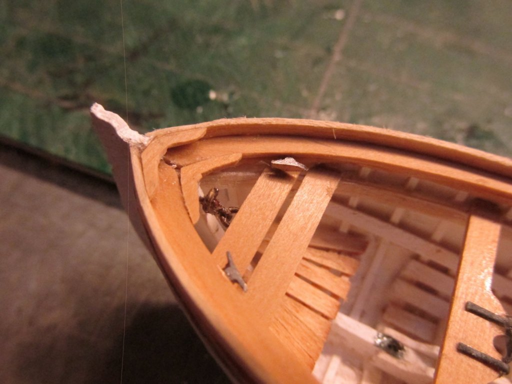
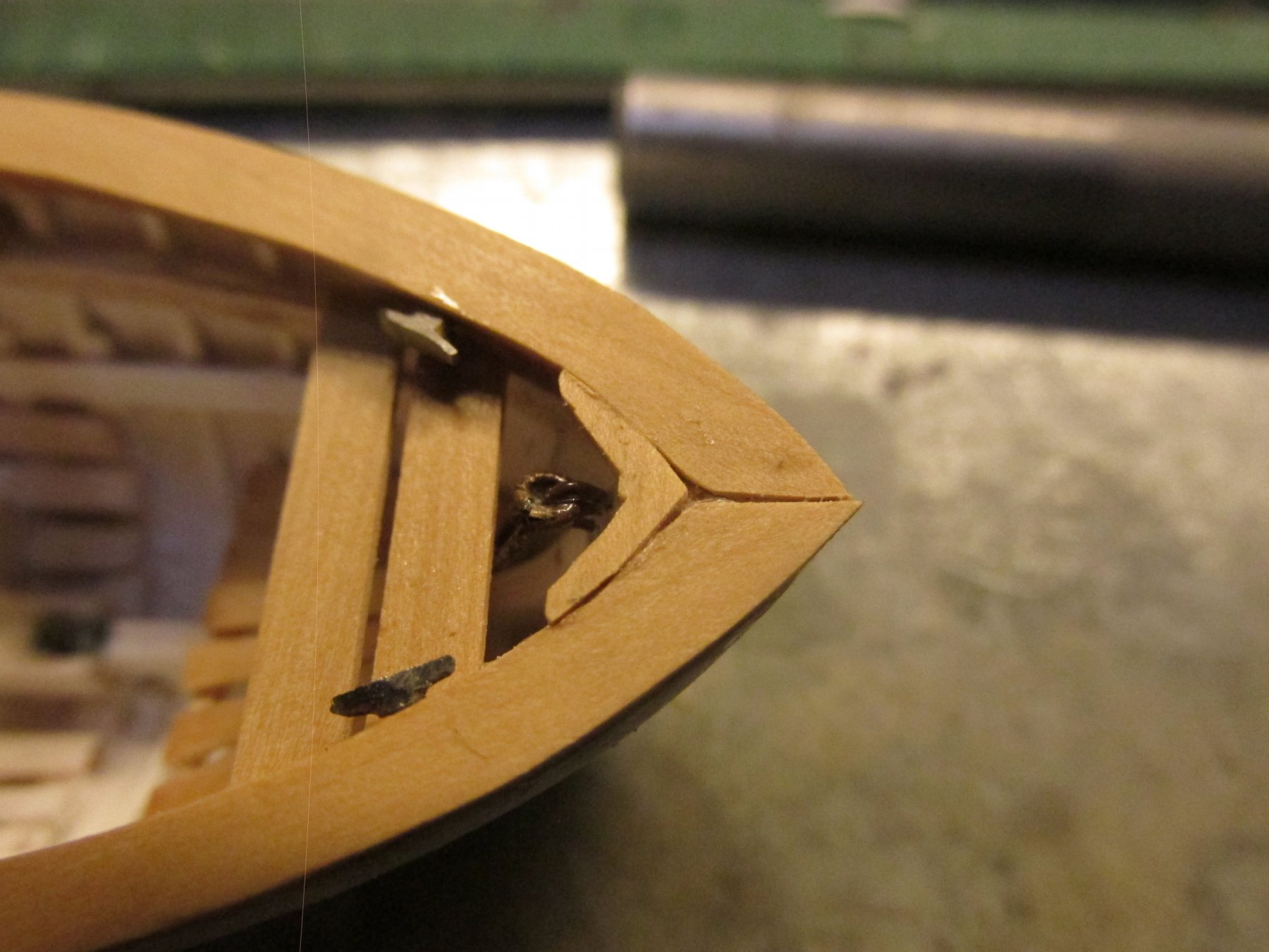
The Stem and Keel
Before I move onto the rail and the rowlocks, I wanted to add the stem and keel to the outside of the boat. The rail needs to attach to stem. The stem was made in two pieces: the rounded bow and the straight upright portion of the stem. Trying to edge bend the 1/8” x 1/16” stock was near impossible. Once the stem assembly was fabricated and installed, the keel was added with lots of overhang. The keel widens as it follows the shape of the up to the transom. I made a card template to get the shape, and transferred it to some stock wood. The piece was then fitted and glued into place. All of these pieces, including the knees described above were glued with PVC glue to aid in adjusting the parts. The stem and keel were then painted (not shown).

- coxswain, Geoff Matson, DocBlake and 6 others
-
9
-
Pinnace Lower Horizontal Knees
After a 10-day break visiting Mom in Florida, who turns 99 years young this coming week by the way, and doing my stuff that should have been done while I was gone when I got back, I resumed my “break neck speed” construction of the pinnace.
Using my reduced down to kit size US Navy plans, I made templates for the stern (2 pieces) and bow lower level horizontal knees – a total of three. I could have used the kit plans but the US Navy plans produces a much finer line drawing. These were rubber cemented onto 1/32” bass wood, cut out and fitted into place.
- Jack12477, coxswain, Blue Pilot and 5 others
-
8
-
Were you referring to my Rattlesnake blog (post #758) as the source of your crowsfeet guidance? Boy, you have a lot of faith in me if you did. That build was my first full rigged ship model.
Jonathan
- Canute and Geoff Matson
-
2
-
Just catching up as I was doing one of my visits to Mom (she turns 99 June 5). I really like your supports on top of the pedestals. I never really liked those simple U-supports (brass or otherwise). They just seemed to me me that they put too much stress on the keel. That added shoulder appeals to my engineer side. I graduated many, many years ago as a civil engineer but never practiced as such. What kind of wood did you use? It looks like walnut.
- Canute, Omega1234, SawdustDave and 2 others
-
5
-
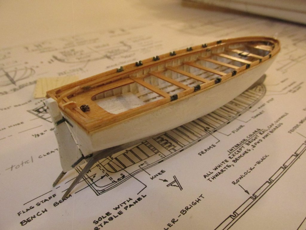
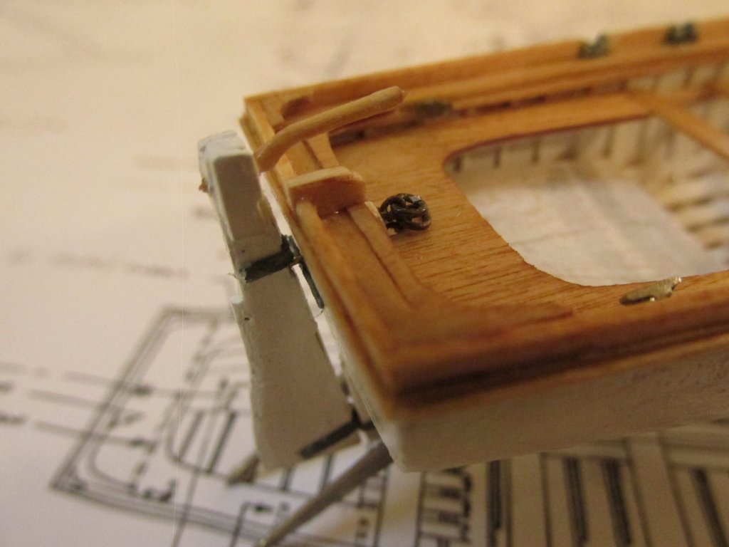
Pinnace Cleats
I’ve noticed that some builders have installed the pinnace cleats and others not. The practicum does not. Being the crazy fool that I am, I made the attempt.
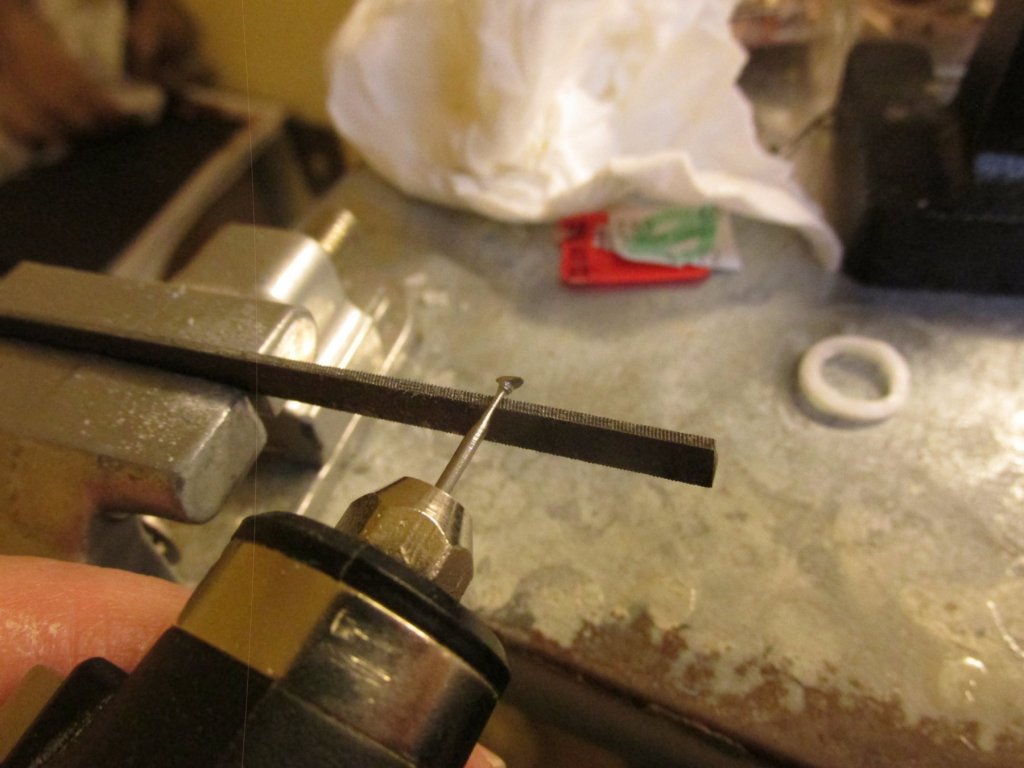
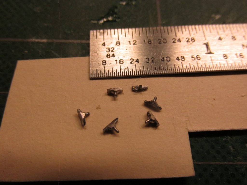
Using a technique that as far as I know, no one else has used, I made six cleats. The first four images below are from my Rattlesnake build where I needed one very small cleat. The last three from this build.
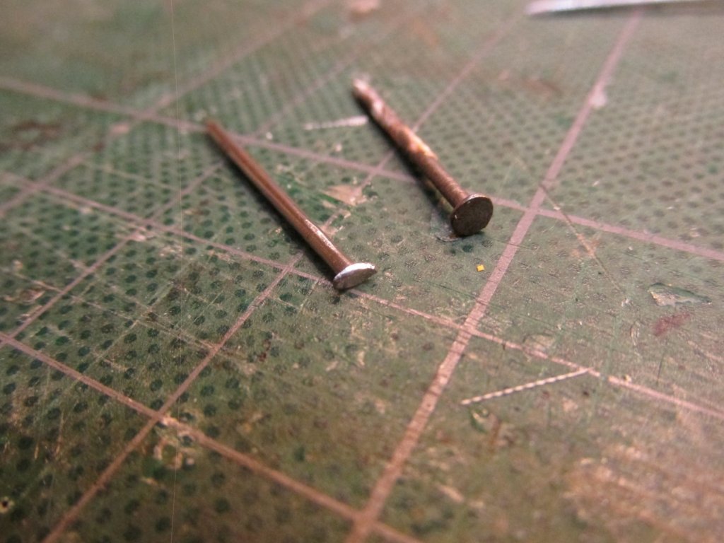
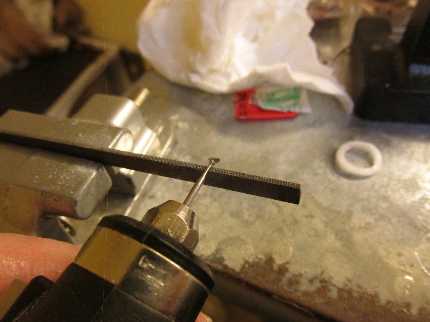
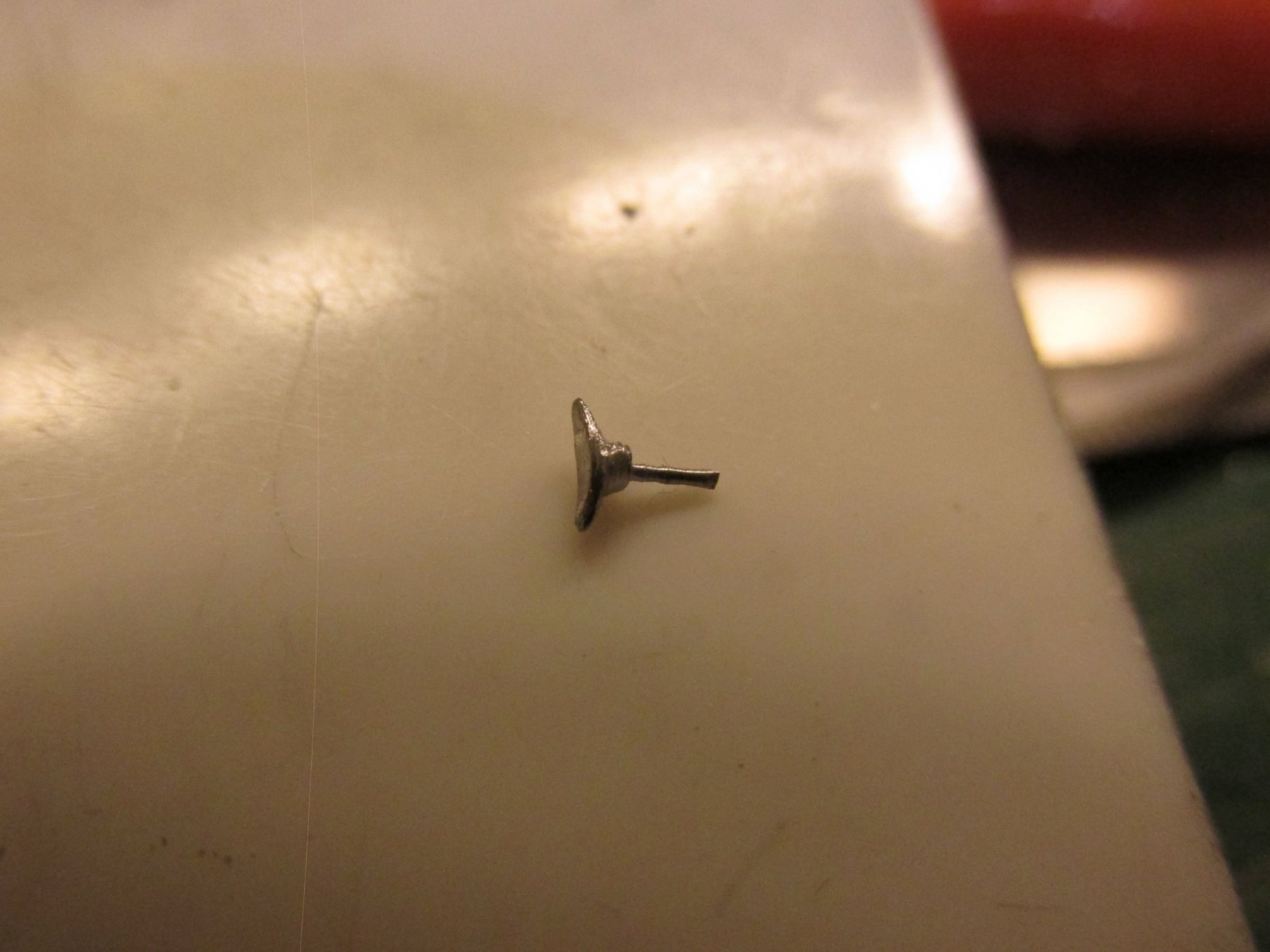
The US Navy plans give the dimensions of two different size cleats, 8’ x 1 7/8” (the other being 6 ¾” x 1 5/8”). At this scale, it won’t make much difference. I chose to base mine on the larger of the two which worked out to be approximately 1/8” x 1/32” at scale.
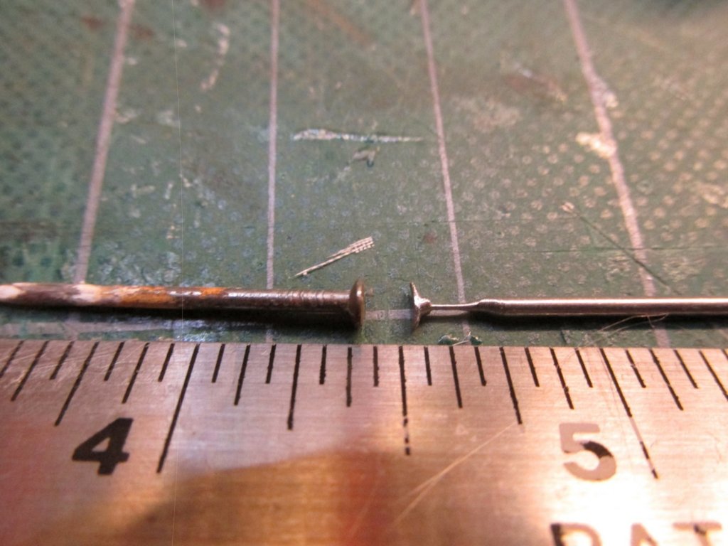
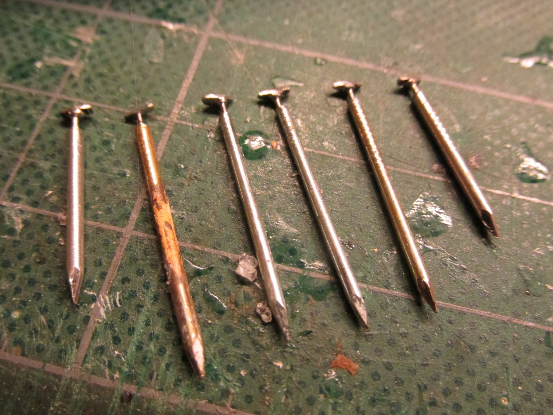
Using some picture hanger nails, ones with a flat head, I filed off two sides of the nail head right up to the nail shank. Then placing modified nail in my rotary tool, I ground it on a file held in a vise. When done, I was left with a very stubby shank just under the modified head followed by a very thin shank. The thin shank is what will anchor the cleat into the wood. Holes were drilled into the rail and the six cleats were then CA’d into place.


-
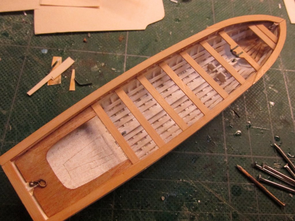
The thwarts were made from 1/32” boxwood. The mast thwart clamps were made from card stock (file folder) and painted black. I tried using the styrene, but due to the size of the pieces, trying to hold them in place while trying to glue them with CA (PVC couldn’t hold the plastic) was neigh impossible. With the card stock, I could use the PVC and its tackiness would hold the parts in place as I maneuvered their positions. These pictures were taken prior to any staining of the thwarts.
- BenD, CaptainSteve, DocBlake and 5 others
-
8
-
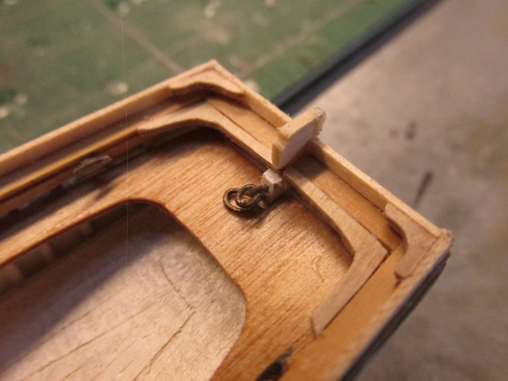
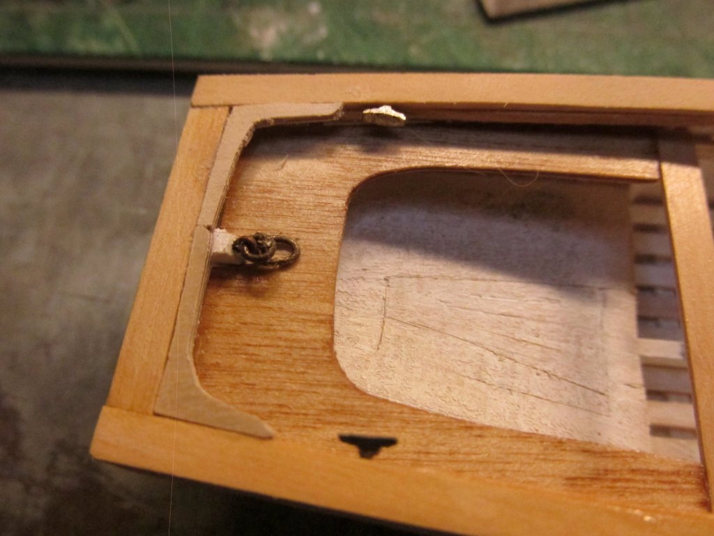
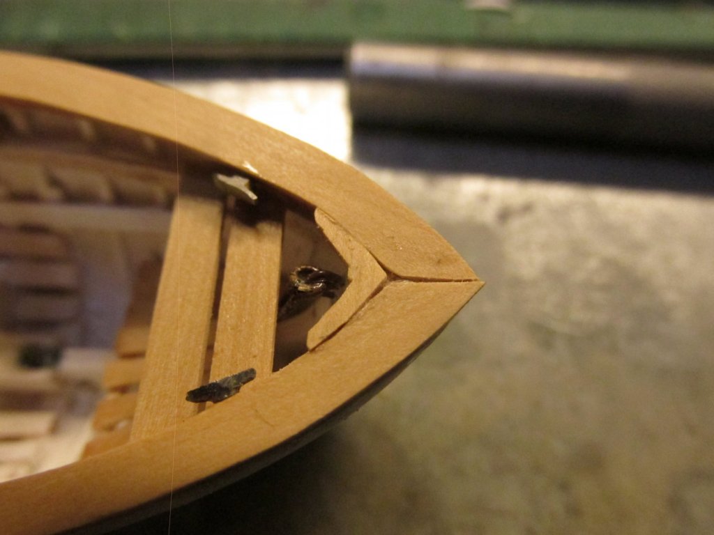
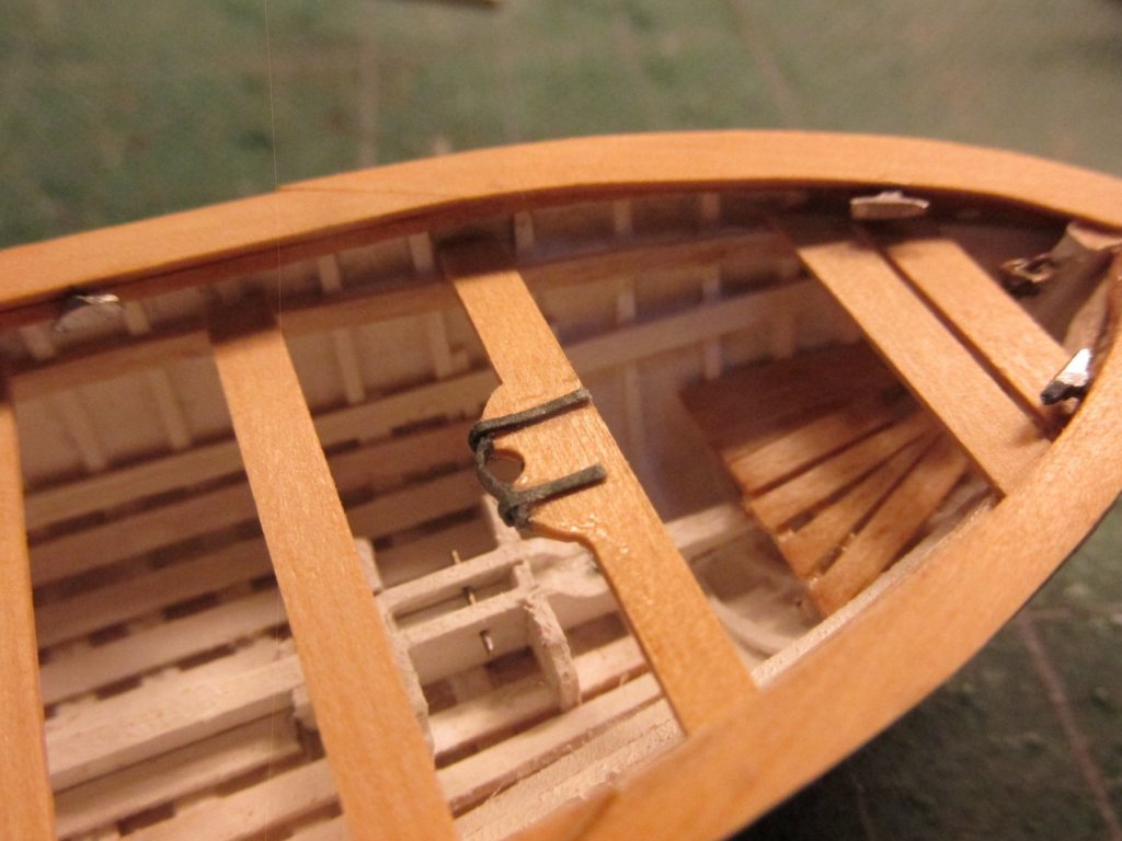
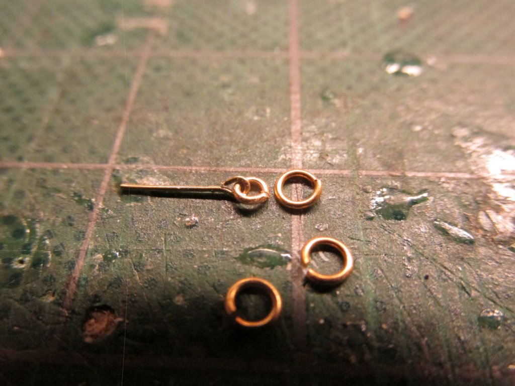
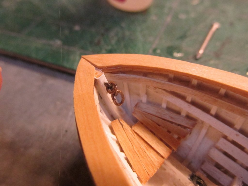
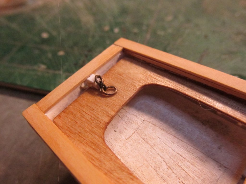
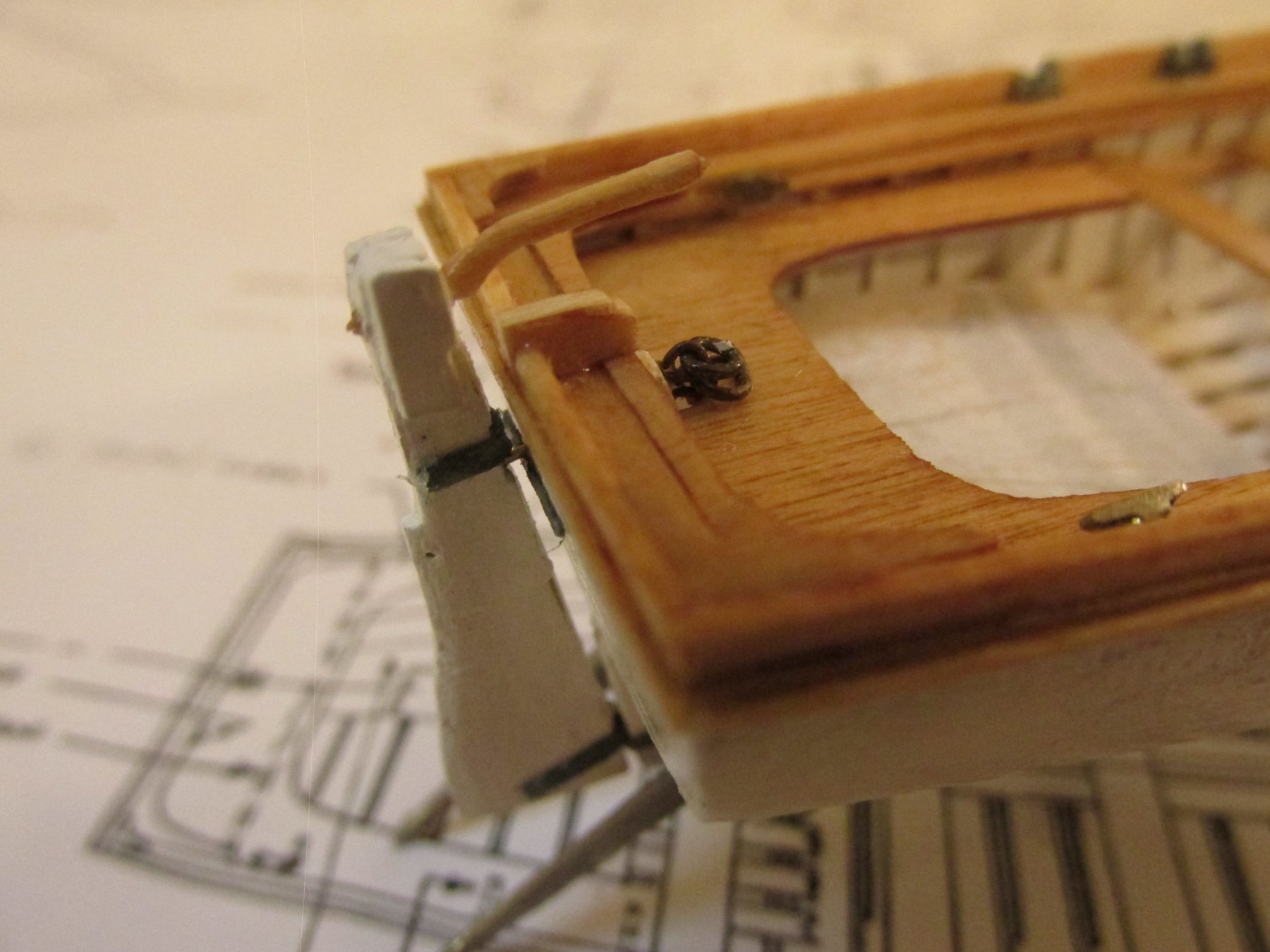
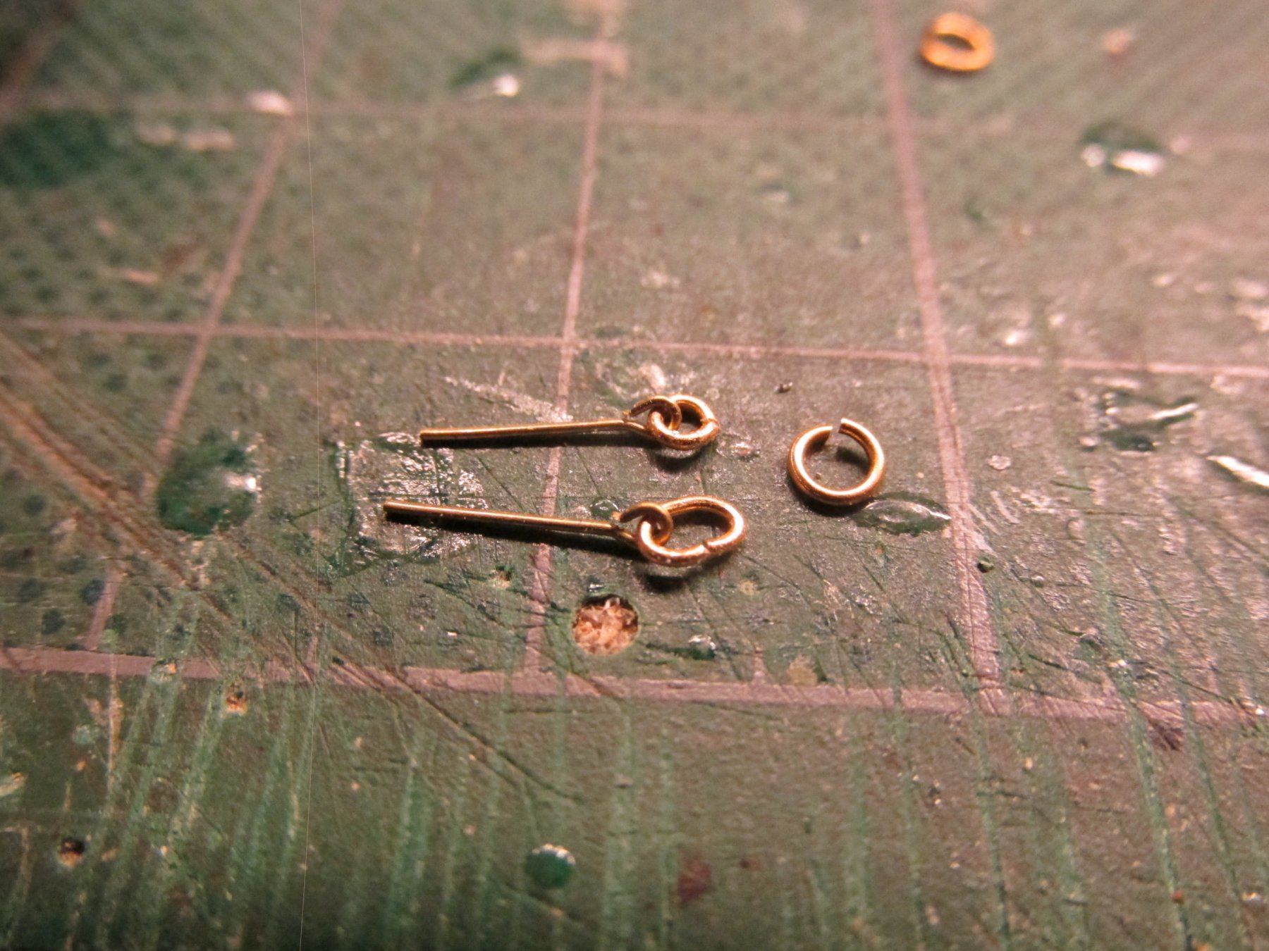
To approximate this at scale, I used the smallest ring I had: 1/8”. For the top ring, about a quarter of the circumference of the ring was snipped off and the resulting ends joined together. This reduced the size of the ring closer to scale. The bottom was squeezed to the width of the top ring and resulted in an oblong shape. They were then installed

-
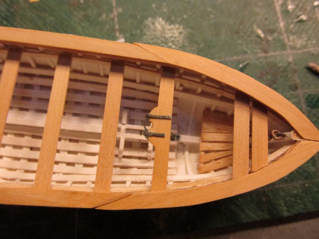
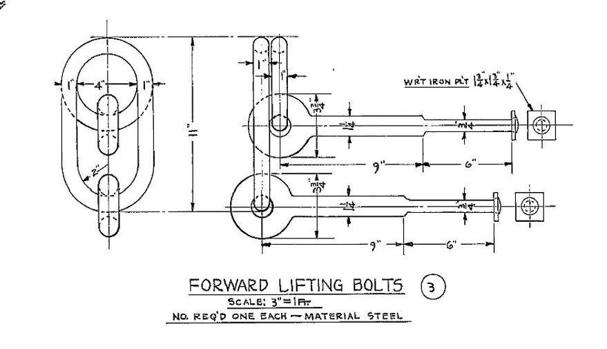
Pinnace Thwarts
Continuing my way from the bottom interior up, the thwarts were next. But before I started those, I thought it would be prudent to install the lift fittings double eyebolts at either ends of the boat. Based on the dimension shown on the US Navy plans, 1/16” eyebolts closely approximated the scale needed. Each eyebolt had a ring. The lower eyebolt’s ring was oblong in shape such that it came to the same height as the top eyebolt’s round ring when pulled to the vertical position. The width of both rings were the same.


USS Constitution by xken - Model Shipways - Scale 1:76.8
in - Kit build logs for subjects built from 1751 - 1800
Posted
OK, I accept the challenge 8-).
This is from The Masting and Rigging of English Ships of War 1625 - 1860. by James Lee I hope it's clear enough to read.
Stunsails.pdf