JSGerson
-
Posts
2,652 -
Joined
-
Last visited
Content Type
Profiles
Forums
Gallery
Events
Everything posted by JSGerson
-
 I don't have a milling machine, but I do have an X-Y table which I attach with C-clamps to an old Dremel drill stand. Of course the problem with that is getting the X-Y axis lined up properly which is a real pain. I was curious as what kind of milling bits the Proxxon machine uses. Would they fit a Dremel style rotary tool? Jon
 -
The halyards then pass through the leer block and down towards the deck. There, just above the forecastle deck the halyards terminate at a double block. The double block is rigged with 0.45 mm line to a double block on the deck next to the main mast. The deck double block is connected to a ring which in turn is connected to a deck eye-ring In addition, the yard is secured to the mast with two 0.45 mm rope loops starting on either side of the mast, which allows the yard to slide up and down the mast as well as pivot. I tried getting a clear image of the double blocks, but getting a camera in there was very challenging. BTW, I broke my hand rail by the fore castle ladder, which I will have to re-glue. Not sure if I should wait after more stuff is installed or do it now while I still have clear access to it.

- 974 replies
-
- 6
-

-
- rattlesnake
- mamoli
- (and 1 more)
-
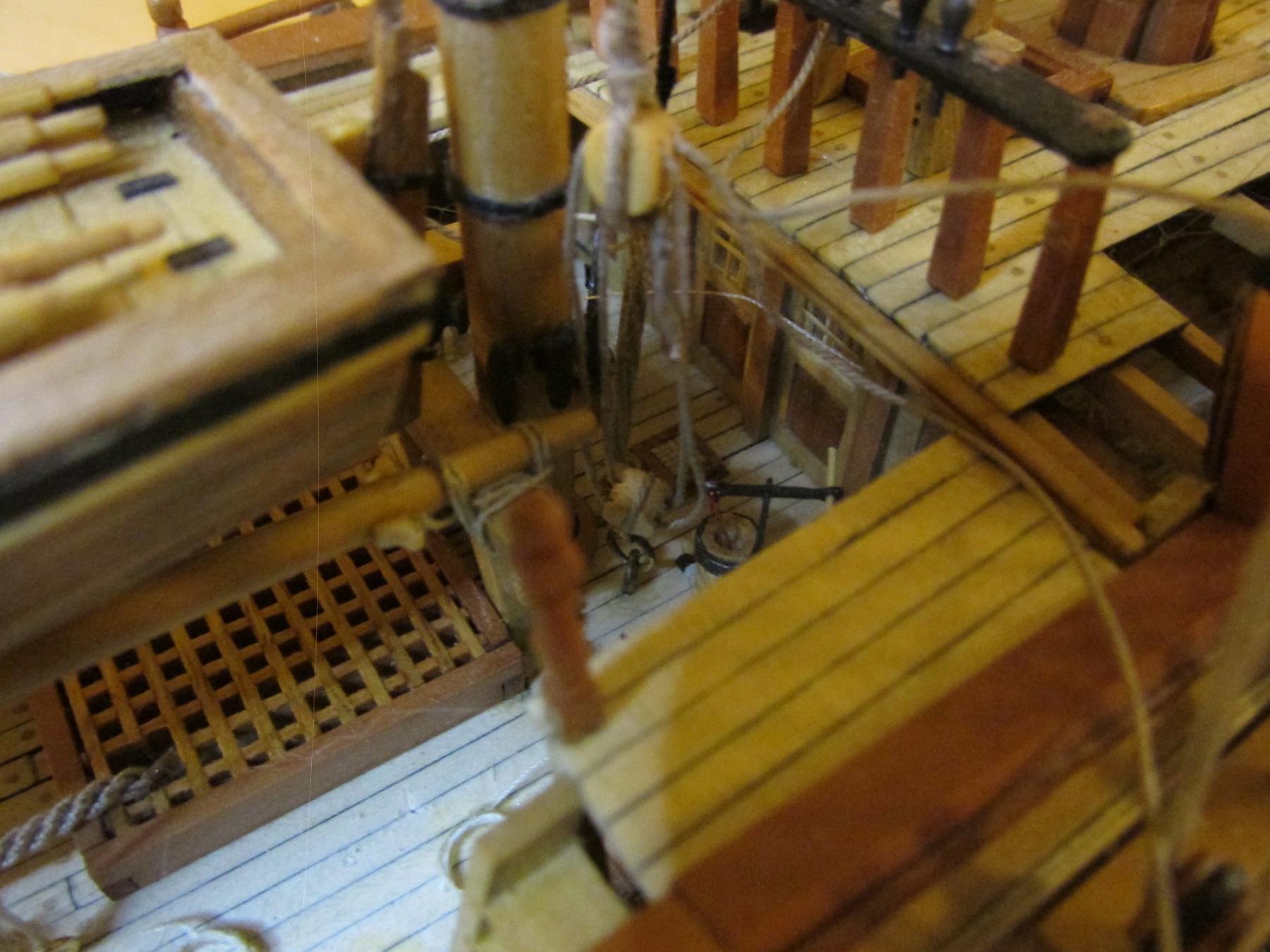
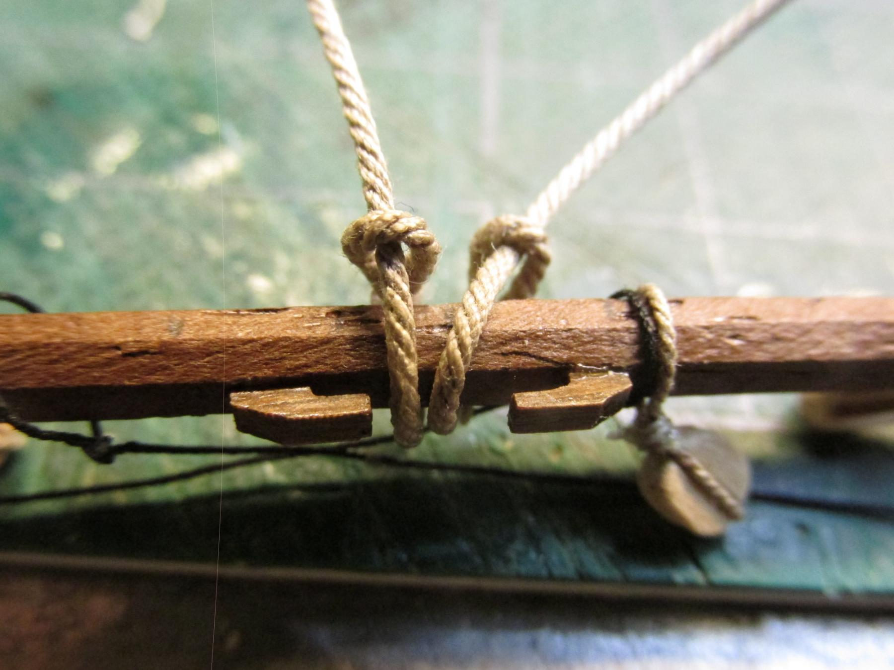
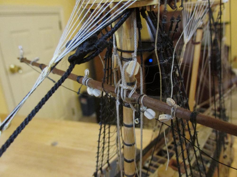
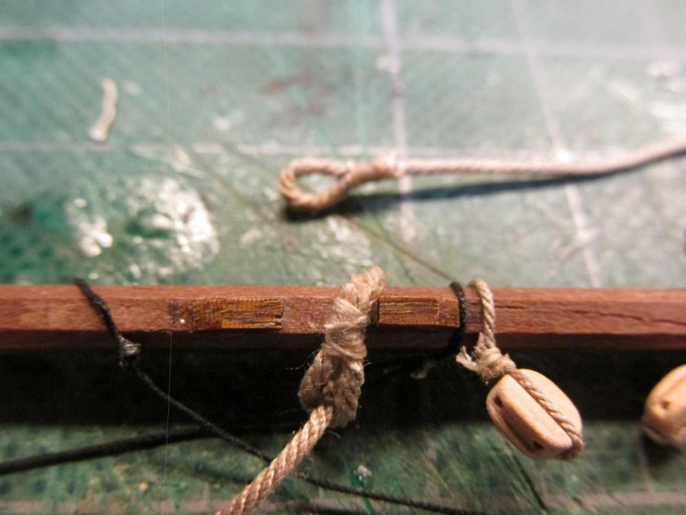
Main Yardarm The first yardarm is now on the model, not fully rigged, but still, on the model. This was accomplished by first making an eye splice at one end of a 0.80 mm leer halyard, looping it around the main yard inside the yard’s center cleats and threading the other end through the eye splice and pulling it taught. The first photo below shows one halyard on the yard and the other halyard lying behind it, waiting to be wrapped onto the yard. The second photo shows both attached.

- 974 replies
-
- 6
-
-
- rattlesnake
- mamoli
- (and 1 more)
-
Those lids are VERY delicate and easily knocked off. Just about all of mine are. If you feel comfortable about it, I would suggest that you hold off from installing them now and save yourself the heartache of breaking one or two or more off and losing them. I won't be reinstalling mine until after I finish the rigging...if I live long enough 8-) Jon
- 481 replies
-
- 1
-
-
- rattlesnake
- model shipways
- (and 1 more)
-
I thought you did. I asked the question for others who are following your build who may not have thought about the consequences of adding a support deck. I wouldn't have known if I hadn't worked on my kitbashed Rattler. Jon
-
If I read and understood you correctly, the support decking was your contribution and not the kit instructions. If that is correct, will that make any difference in the final height of the deck? I'm thinking cannon clearance through the gun ports. I don't know what was the original deck construction plan. When I was making the gunports for my Rattlesnake, I made a card dummy cannon that I could poke through the gunports to ensure the opening were of proper height. Jon
-
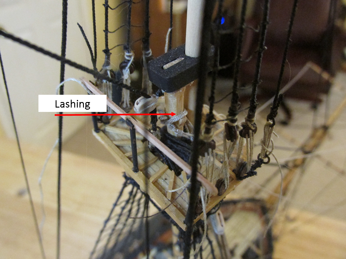
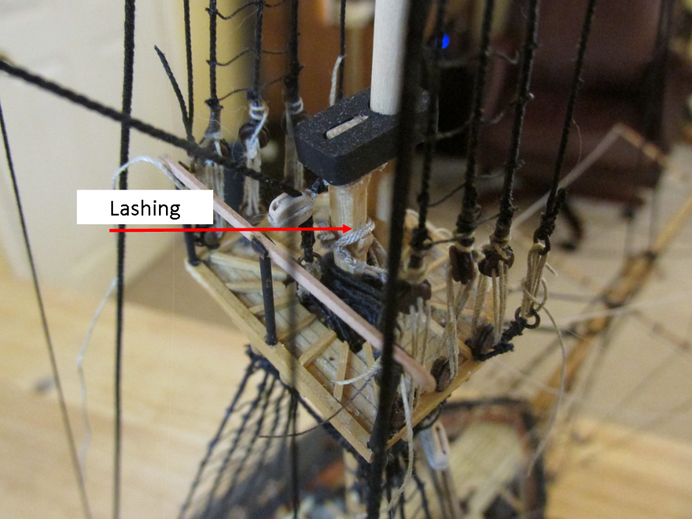
Another missing detail was how the lashings were fixed in place, that is, how were they tied off? I decided to make an eye loop at one end of the lashing, wrap it around the mast twice and pass the bitter end through the eye loop. I originally wanted to seize the end so that one loop would pass through the other. I found this too difficult to accomplish due to the tight restricted working space. I simple made an overhand knot with a dab of CA glue. Right or wrong it’s done.
- 974 replies
-
- 8
-
-
- rattlesnake
- mamoli
- (and 1 more)
-
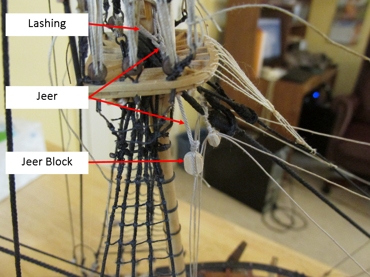
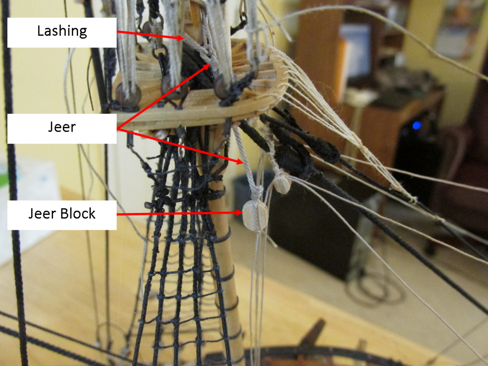
Jeers As I discovered while installing the booms on the Mizzen mast, I could have, should have added more stuff to the masts before I installed them; in this case, the jeers. There is a lashing that goes around the mast just above the mast top to which the jeers are attached. The lashing in turn is supported by a chock on the opposite side of the mast from where the jeer hangs. The Main and Fore mast each have a pair of jeers. There was no instruction as to how many turns of lashing was required but looking closely with a magnifying glass on the Mamoli drawings, it appears the lashing goes twice around the mast. According to Mamoli, the jeer uses 0.80 mm rope. Because the lash goes around twice, I used 0.40 mm rope for the lashing figuring two ropes of 0.40 mm should have the same strength as one rope of 0.80 mm.

- 974 replies
-
- 5
-
-
- rattlesnake
- mamoli
- (and 1 more)
-
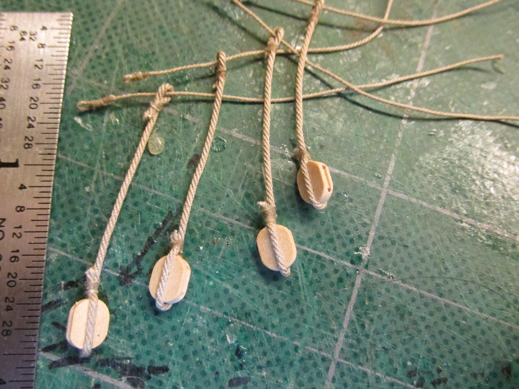
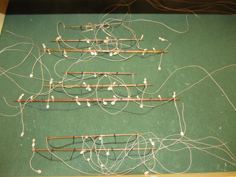
It’s been about two months since I last reported my progress, but if you have been following along with me for a while you will know that in a race with a snail and a turtle, I would lose. Yes, I’m slow. That, plus the fact that I’ve been out of the shipyard doing things that needed to be done and among them, I visited Mom for a week and a half at her condo in Florida As a matter of fact, Mom will be 98 in the first week of June. I did manage to work I on the yards, trying to put as much stuff on them before I install them on the model. I’ve added footropes, blocks, and some halyards to the eight remaining yards. Because I live with a cat, the yards are stored in the workbench drawer which I can close (cats and string…etc.), so I couldn’t lay out all the lines neatly for a photo.
- 974 replies
-
- 6
-
-
- rattlesnake
- mamoli
- (and 1 more)
-
The Conny is my next build as soon as I finish my Rattlesnake (whenever that may be; it's been over 6 years in the making) and I have always intended to "rivet/bolt" my attempt. Per the Hunt practicum (I believe) plastic model railroad rivets were to be used. I always felt they were a bit too large for the scale. I like your method so much better. I look forward to your future postings. Jon
- 117 replies
-
- 4
-
-
- constitution
- model shipways
- (and 1 more)
-
I did understand your remarks, I was just being a little facetious, hence the quote marks. The bowsprit looks great. I just hope it's stronger than it looks. I wouldn't install it until I had for fear of inadvertently hitting and breaking it. Jon
-
I've been away the last week or so and have just caught up on your build. Nice job on the belay ping. Your model model is looking nice, clean and crisp! Jon
-
XKen - you were "complaining" about having to make cleats. Syren Ship Model Co makes wonderful laser cut cleats that you finish yourself. These are a lot easier to work with than home made ones (at least for me). BTW, yours came out beautiful! How did you do it? Jonathan
-
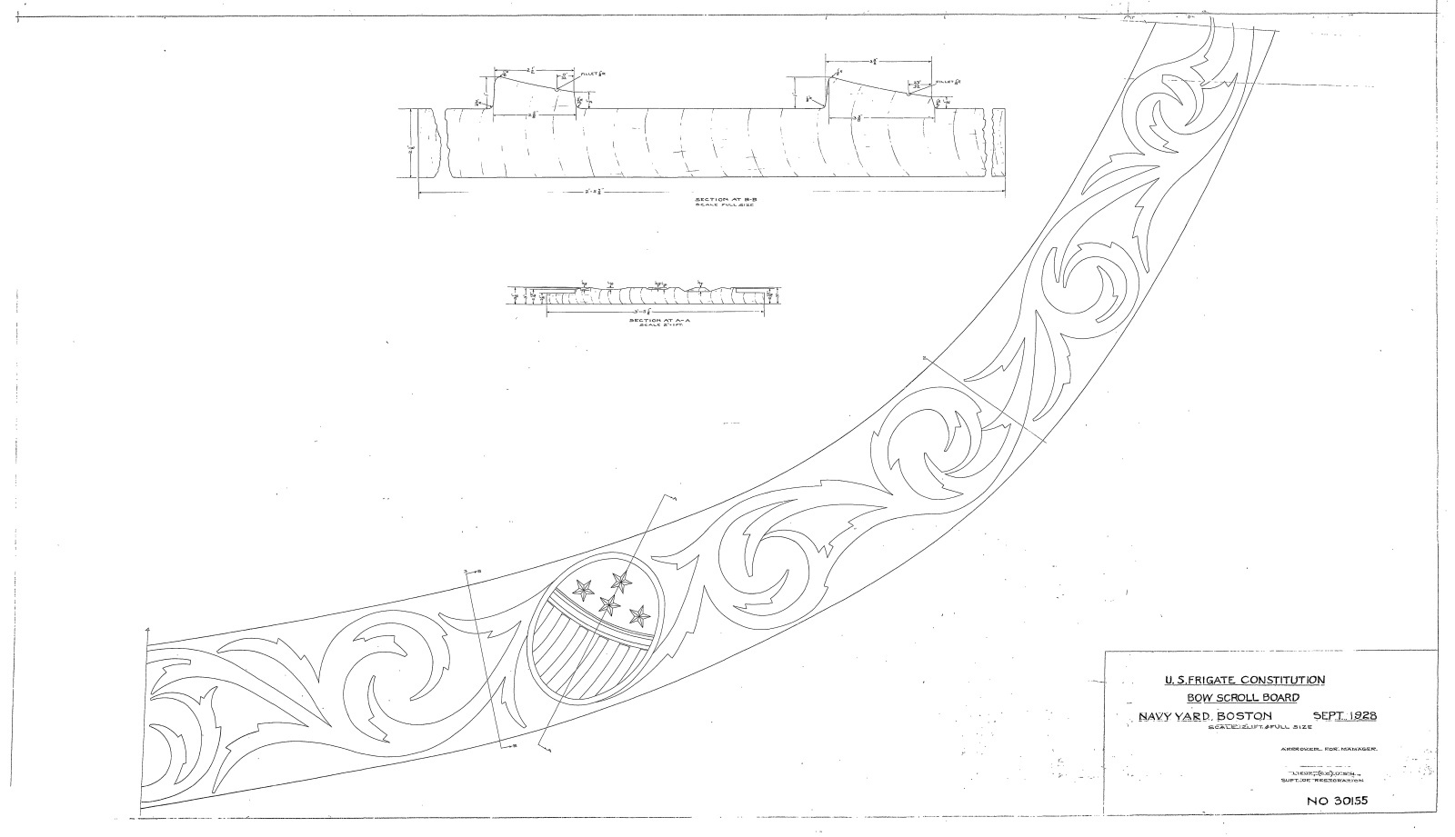
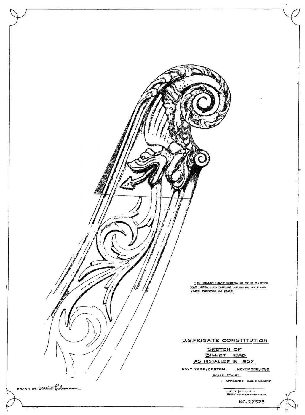
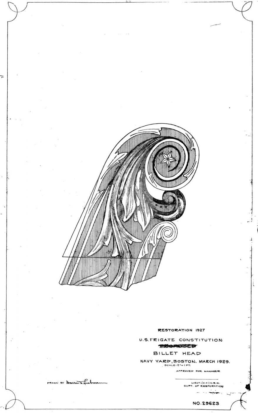
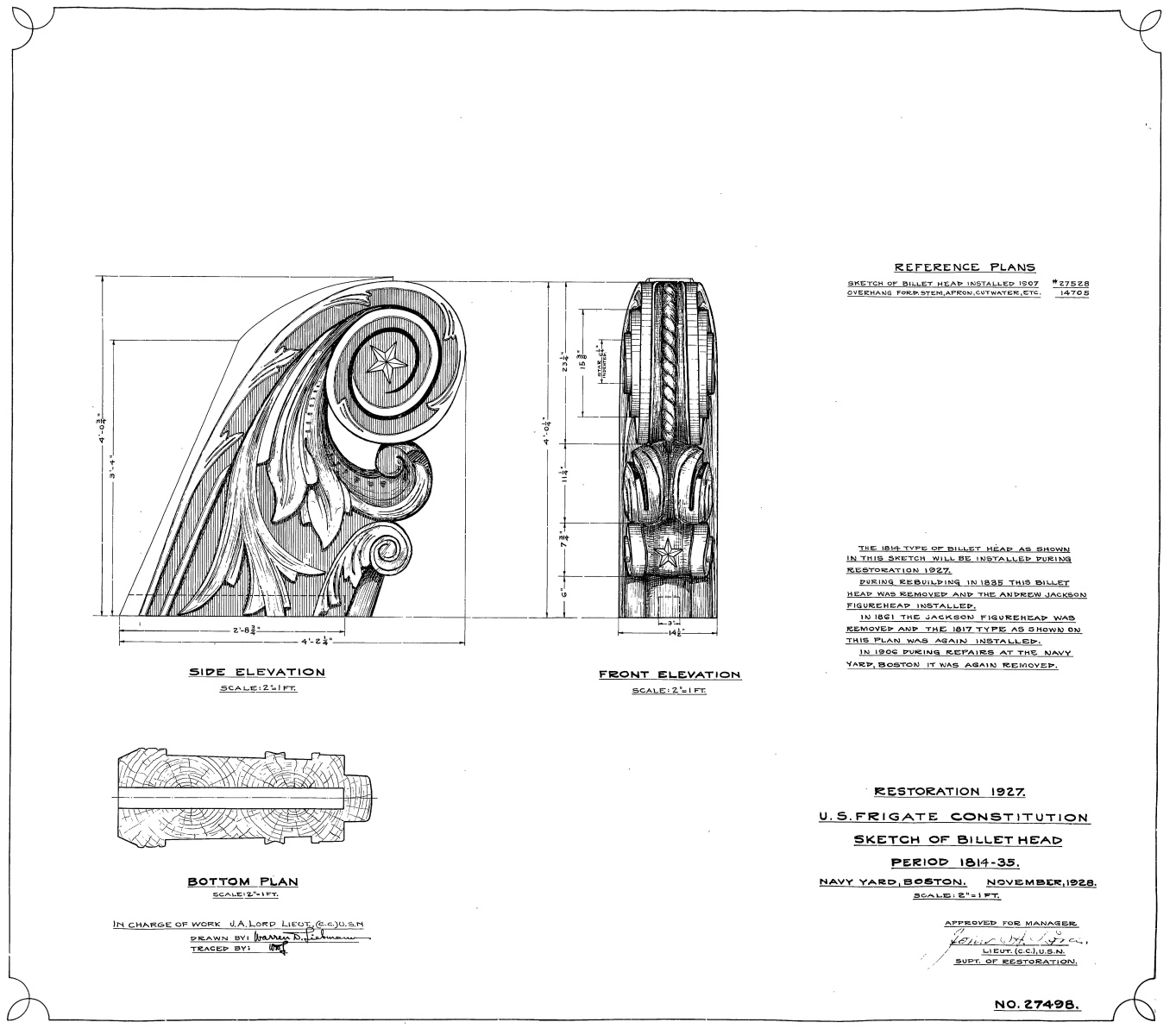
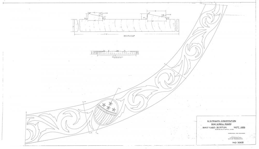
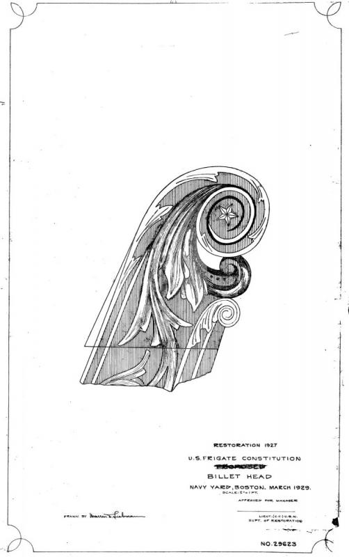
For those who are curious, here are the US Navy plans for the headboard decorations. (Please note that I had to reduce the file size to conform to MSW file requirements). Based on the notes in these drawings, this is how I understand their history: Dwg. No. 30155001: Headboard decorations. Not shown: the billethead and the base wrap-around which I addressed in Post 320 Dwgs. No. 27498001 and 29623001: Billethead 1813-1835 and 1927 to present. 1835-1861: the Andrew Jackson figurehead was used 1861 – 1907, the 27528001 style billethead used Dwg. No. 27528001: Billethead 1907 – 1927 If anyone wants the full size drawings, please PM me with your email address. Jon


-
Wow is right! I never expected this! Making the shield decoration should be interesting. Now I suppose you're going to tell us that you going to cut out the tiny stars in the shield!! 8-) Jon
-
I'm impressed; functional 1:64 scale kevels! Build is coming along nicely Jon
- 481 replies
-
- 3
-
-
- rattlesnake
- model shipways
- (and 1 more)
-
The sound you hear are the "gods" enjoying your build with joyous laughter. They are very happy with what you have done so far. I can't wait to see how you complete the trailboard decorations. I did notice one curious thing with those decorations. I may be wrong as I have not studied the kit plans, but based on the laser etched trailboard you have in place, it appears that the kit has all the decorations on the trailboard when In fact, just a bit of them wrap close to the hawse pipes. I just wanted to make sure you knew now, so if you need to correct anything, this would be a good opportunity. Jon
-
I'm convinced. When it comes time for me on this future build, wood it is. Typically, I'm not a big fan of Basswood (Midwest) and prefer Boxwood due to cleaner surface and cuts (less fuzzys). Can this be done in Boxwood which might be a little less flexible, I don't know)? I've got a Byrnes Saw and can make real fine strips if need be.
-
Beautiful work! You stated that you explored "various alternatives" for the bow stripes and decided to use wood strips. In a number of other build logs, the modelers (e.g., Robert Hunt's practicum) used white polystyrene in lieu of wood, I assume for the flexibility of the pre-colored white plastic. On the surface it seems plastic would have been the obvious choice. I rather like your choice of wood, but what were your reasons for rejecting the plastic (assuming you considered this)? What other methods did you reject? Jon
-
I always thought the MS kit plans were based on the 1926 restoration (I haven't done much research to confirm that) ,hence the fiddle head. Another example, is the model's high waist, a 1926 addition. The last restoration prior, to the current one, restored the lower waist. Nobody really knows what the transom looked like 1797. The fact that the box says 1797 just means that's when it was first commissioned. Jon
-
You did a beautiful job on the seats and gratings. When the time comes, I hope mine will even approach what you accomplished. Out of curiosity, if you look at the second photo in post 296, the grating surfaces appear above the level of the rail because you can't see where the stiffeners meet the rail. In your last image, the grating tops are flush with the rail. Was this deliberate? I don't mean to deride what you've done, like I said, I'd be very happy, no, proud to approach your level of craftsmanship. When do you plan on installing the bowsprit? I'm thinking about the gammoning that will be required and it looks like it getting a bit confined in that area. I ran into that problem with my Rattlesnake. Beautiful, just beautiful Jon
-
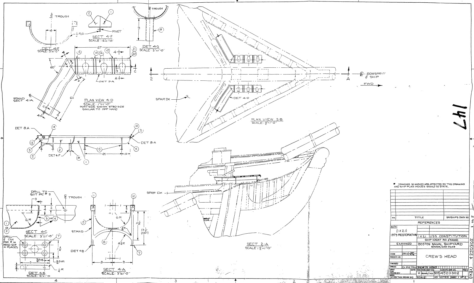
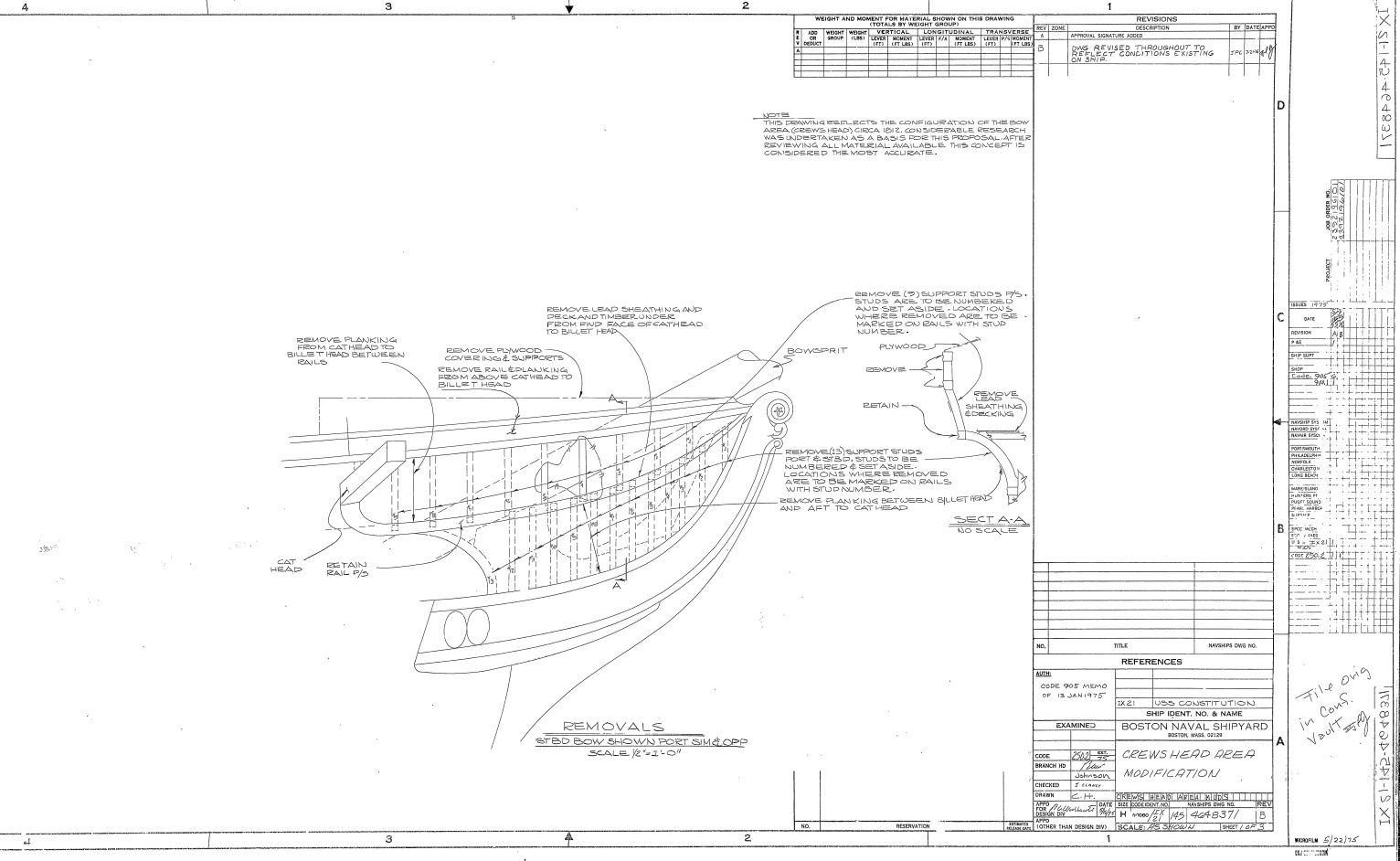
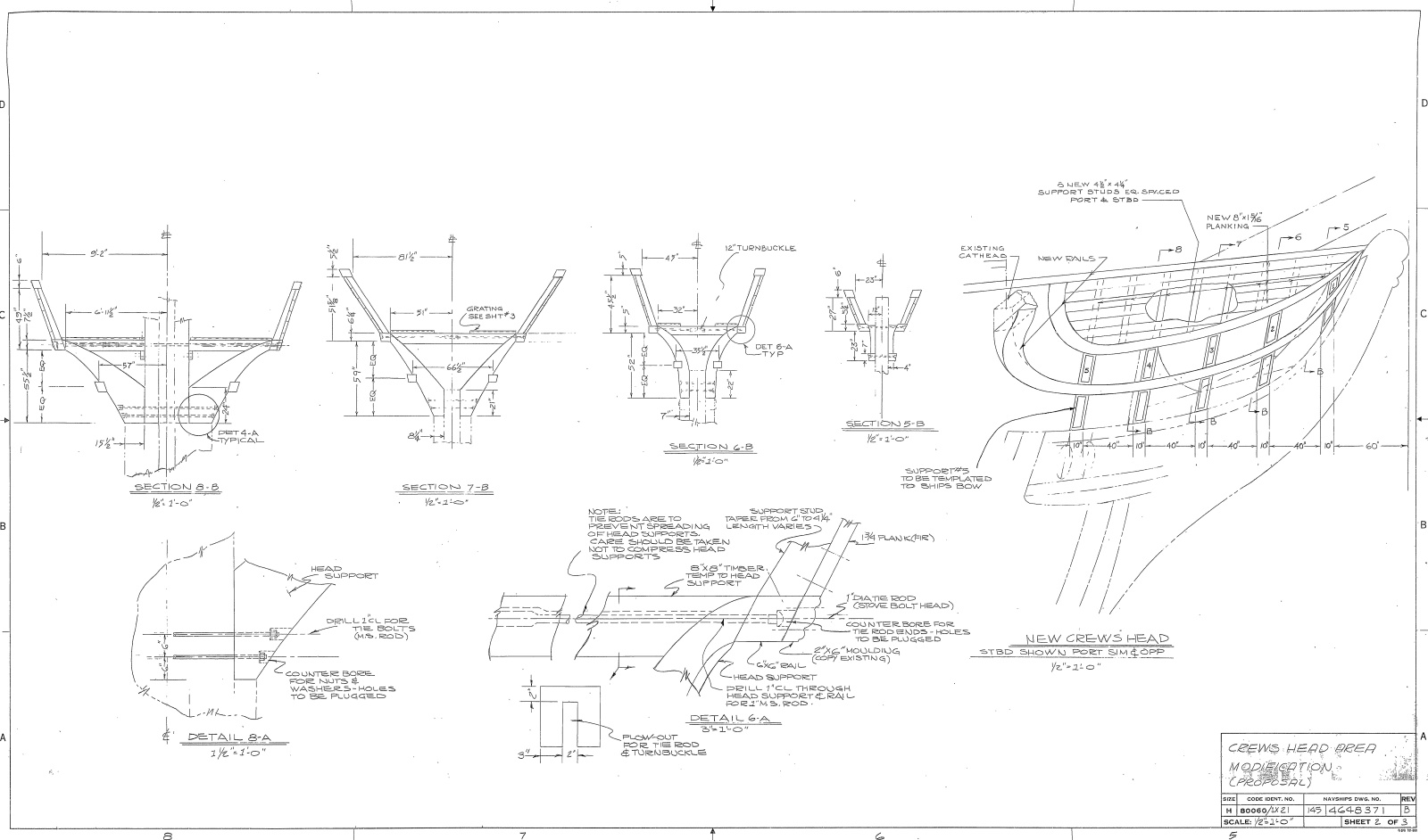
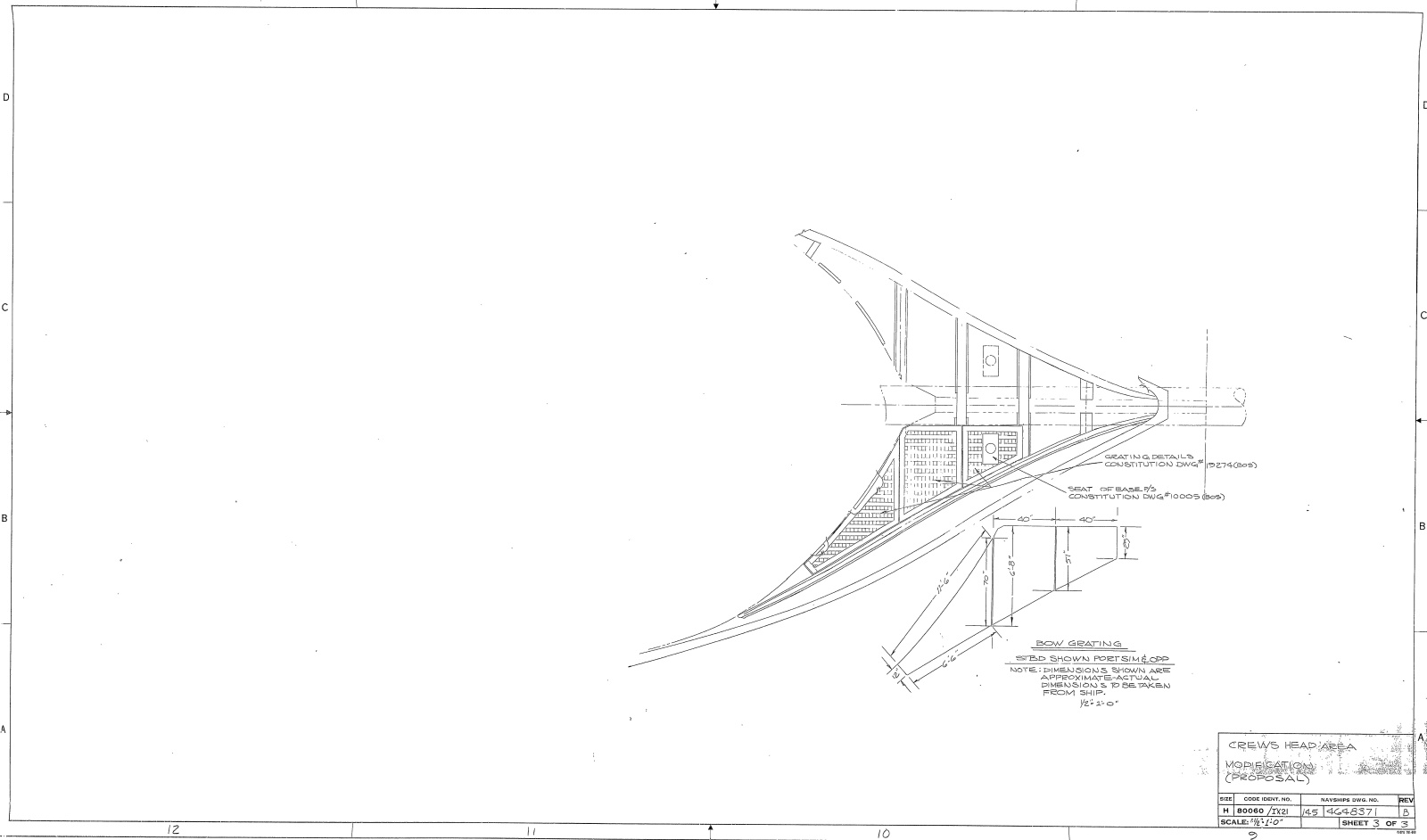
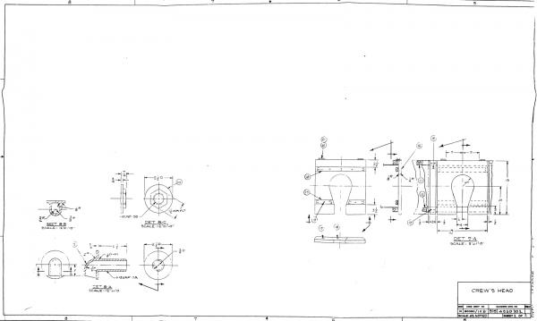
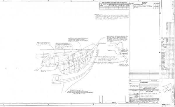
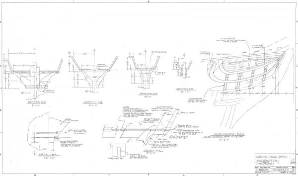
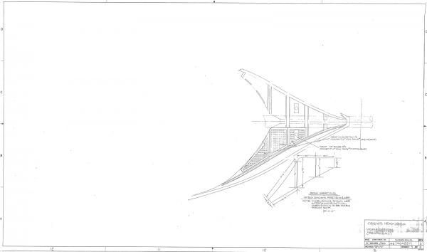
I did some digging and found these plans from the US Navy: 4520302001 - Crew’s Head (located on 2001 CD not available anymore) 4648371b - Crews Head Area Modification Sheet (located on present CD for sale) I had to reduce the size/resolution in order to post them. If you would like the full size, PM me with your email address and I will get them to you. Jon

-
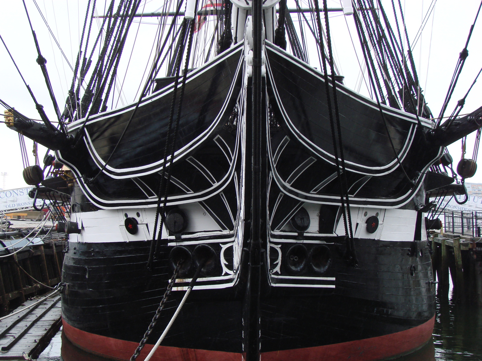
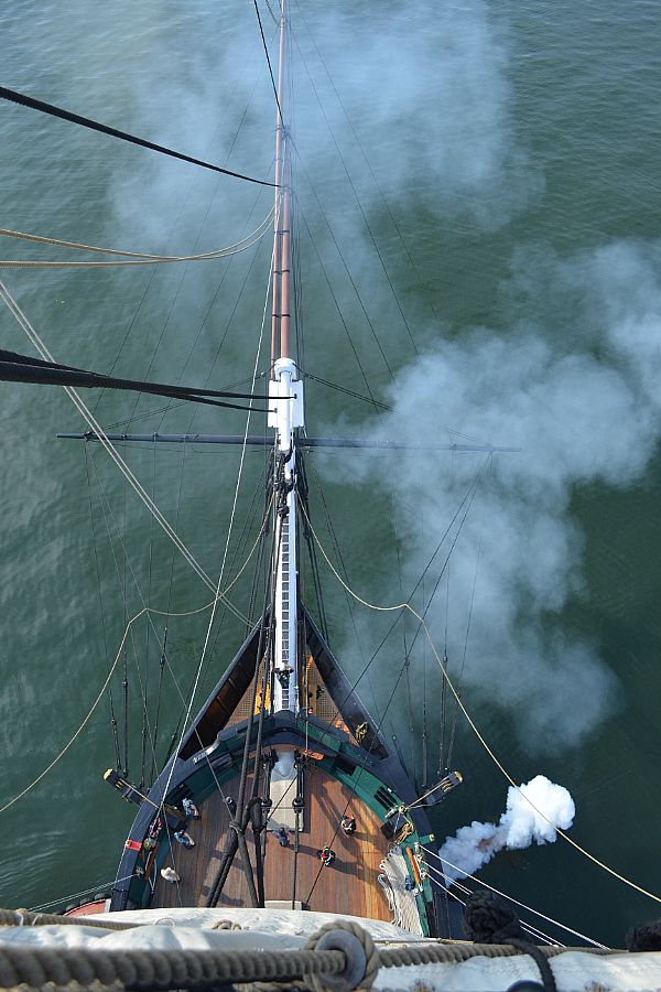
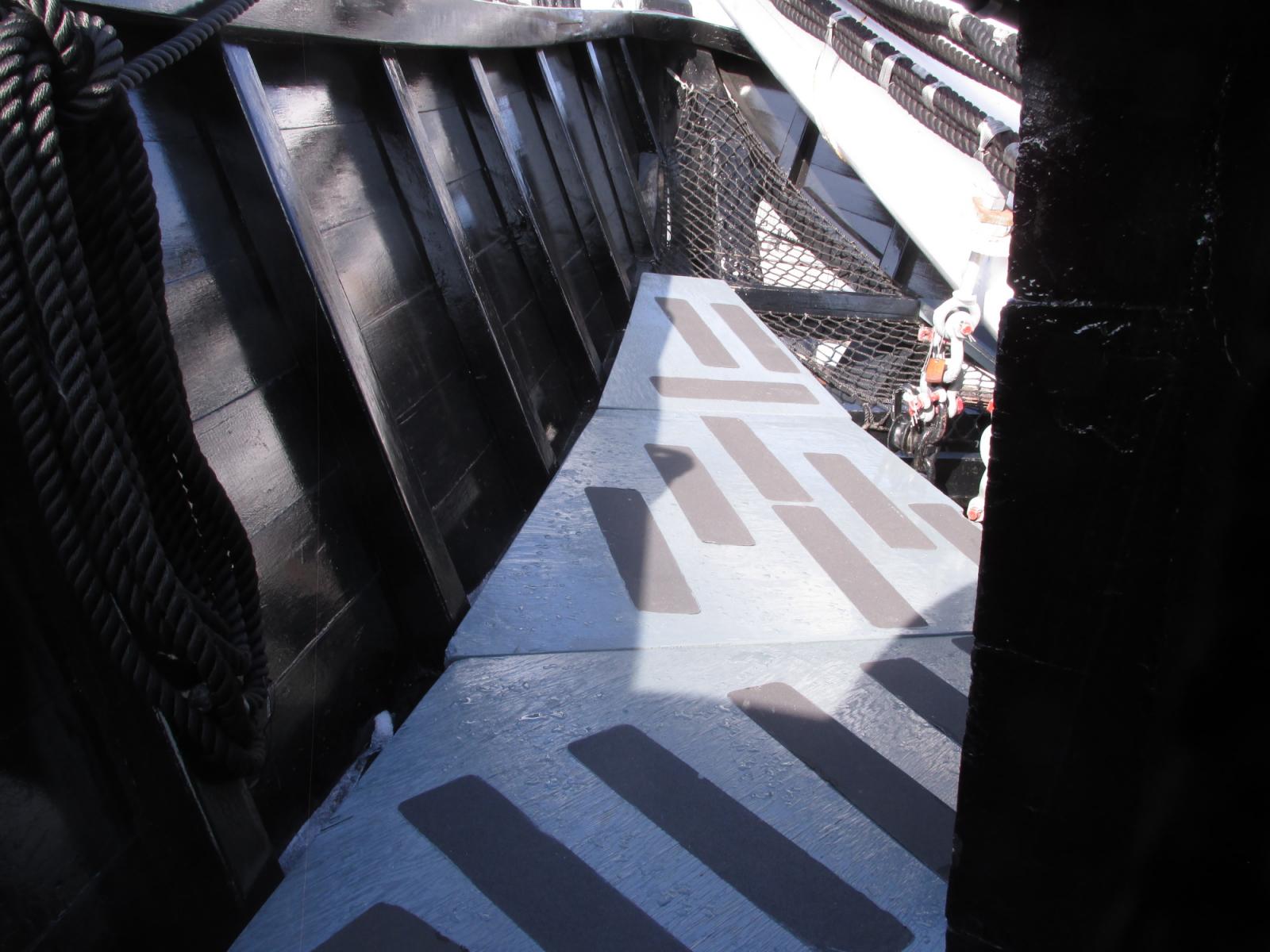
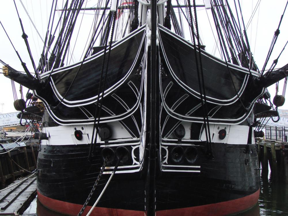
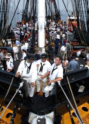
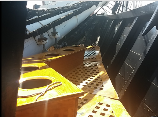
A view of the bow from the angle in your last image are exceedingly rare due to the fact that the public is not allowed to go there. I have been looking for those same images as you for the last couple of years in anticipation of my building the Connie as my next project. Here is what I have so far


-
You made the right decision. The way you know that is you feel much better now that is is done. If you are going to do something, you might as well take your time and do it right. You saw the problem and you fixed it when it was easier (not necessarily easy) to fix (now vs later). It's a hobby, there is no rush, and in many cases there is no "right" way, just "your" way. Jon
- 117 replies
-
- 6
-
-
- constitution
- model shipways
- (and 1 more)
-
There has been a lot of discussion in the past about rope coils. Now, I am the last person you would want to ask about them. I am not a sailor and, as I have mentioned in the past am working on my first real build. The following quote is something I kept as part of my personal library of model building knowledge. Unfortunately I neglected to record whom I got it from, but I present it here on it's own merits: Sorry to "throw cold water" on such an interesting topic, but nice as those flat coils lying on the deck of a model look, did they really have them on full size ships? I mean what would happen when a heavy sea washed over the decks? You make a good point. 'Decorative' as rope coils might look on the decks of a model, this wasn't normal ship practice. There was a good reason for this – it encouraged rot. Everything was done on board ship to minimize wear and tear (which after all means money spent) and this included the running rigging. Wherever possible rope coils were hung from the belaying pin they were associated with, or perhaps from a cleat if a large rope, so that no part of it touched the deck. Apart from gravity, this also allowed air to circulate around it and so dry it. Ropes left lying on deck would probably never dry out, being repeatedly wetted by either salt or fresh water. If you consider a deck (with rope coils laid on it) which has just been rained on, or a sea has come over the side, the deck itself might gradually dry out, but you can bet that that part of it under the coils will still remain wet or damp – an ideal situation for rot to set in. Apart from that a heavy sea coming aboard would also leave the coils in a hopeless tangle, so coils on deck are also a safety hazard. From experience, the only time you would normally see a large amount of rope on deck, is when the ship is either setting or furling sail, or engaged in some maneuver such as tacking or wearing. At these times, you have to be very careful where you put your feet, and you should never stand on a rope in this situation if you can avoid it – in case it moved without warning. The last order normally given after such an operation was to 'tidy up the spaghetti' – i.e., coil up, and hang the running rigging from its pin. I should mention that this practice is followed today, even though the rope concerned might perhaps be modern Polypropolene, which will probably also deteriorate eventually.