


JSGerson
-
Posts
2,646 -
Joined
-
Last visited
Content Type
Profiles
Forums
Gallery
Events
Everything posted by JSGerson
-
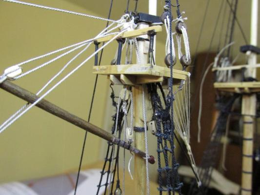
 More questions if you don't mind. I assume the "chafing fish" is the shell like covering over the mast. As it appears to me, it looks like a smooth thick veneer surface covering half the circumference in the lower potions and completely around the mast in the upper. You chose to build this up from strips of long tapered wood going around the mast almost like a long thin wooden barrel. How did you achieve that and squeeze it to such a tight fit? I have no idea what the plans mean when you stated "just add filler." What did that mean - lather on wood filler and carve it? As a novice, I might have wrapped a thin card-like or polystyrene sheet material around the mast to achieve the effect. Obviously yours, being well executed, is a far superior method. Jonathan
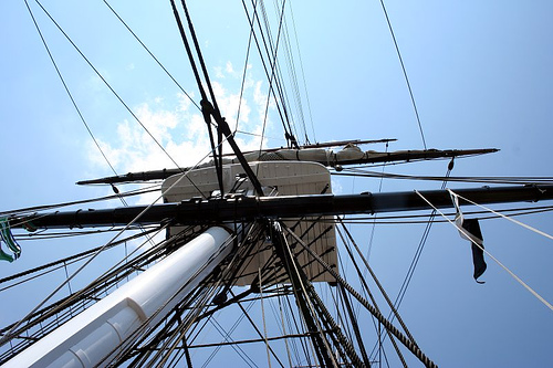
-
Out of simple curiosity I noticed that the style of steps you made, which appears to match the period style of the Constitution, does not match what is presently on the ship. What were you using as a model for your steps? BTY, you done a beautiful so far. Any more details as to how you made the round eye bolt "thingys"?
-
That helps a lot Ken. I'm still putzing around with the yard rigging now and should I feel like I'm going out of my mind, I may just do what you did just to get my hands back on wood parts again. I initially had visions of duplicating Salty Sea Dog's efforts on his C.W. Morgan Whaleboat Post #375 but that was 1:25 scale. Placing the buckets between the guns sounds simple enough...yeah, right! 8-)
-
JT - PM sent
-
I didn't make buckets because when I was at this stage I was still following Bob Hunt's practicum exclusively, not paying too much attention to the kit plans, and he didn't address these. Therefore, I didn't know to provide an area to store them on deck. When I did realize there were buckets, I almost didn't recognize the Mamoli supplied cast metal buckets were in fact buckets. So the model still stands bucketless. What was the process you used for making the buckets?
- 481 replies
-
- 1
-

-
- rattlesnake
- model shipways
- (and 1 more)
-
Chuck, are you considering offering your ropewalk as an item for sale on Syren?
-
Here is something to consider: the Wood Supplement Packages originally from HobbyMill. If you are following the Robert Hunt Constitution practicum like I will when I start my model of the Conny, he talks about making certain wood changes on the deck: Hatch Combings, Main Rail, Fife Rails, Fenders, Binnacles, and Life Boats. At the time I bought my kit, HobbyMills was still operating (that role has since been taken over by Crown Timberyard) and I could and did purchase all of the supplements for a total of $85. Whether or not Crown Timberyard also offers these packages, I don't know. It might be worth looking into. If you are interested, I could send you the original HobbyMills description which indicates where in the practicum the substitutions are to be made, what they are, and the pricing. Jonathan
-
Don't feel guilty about not following the practicum to the letter. I'm following Bob Hunt's instructions for the Rattlesnake as a complete newbie and even I deviated from the written word when I though a better sequence was called for. If I remember correctly, somewhere in the my practicum he states that if you find a better way of doing something than he was showing, go ahead and do it. Your doing good, so keep at it. Jonathan
- 117 replies
-
- 5
-
-
- constitution
- model shipways
- (and 1 more)
-
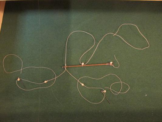
Chuck had two tables at either end of the room approximately 20' apart; one for each end of the rope walk with one end clamped down. The power drill turned the mechanism on the unclamped side which was was held back with one hand to maintain tension. After the unclamped walk had moved a predetermined distance - six or seven inches(?) (determined from past trials), it was clamped down and the other side was used, Because the drill was turning the gears from this side now, the twisting was reversed and the three (or four) lines wrapped around each other creating the rope. After the rope was pulled through some bees wax he was done. The rope did not unravel. Hope this helps Jon
-
In case I haven't mentioned it to you before, Chuck Passaro former Director of NRG and owner of Syren Ship Modeling Co who make such wonderful miniature rope, uses this very same "cheap" ropewalk. He did make one very important change. He took off the the handles and replaced them with a Philips Head screws so he could turn the mechanism with a power drill. I saw him make a 20' rope from initial threading of the walk to final product in less than five minutes. The drill made all the difference in the world. Just thought you might want to know. Jon
-
Yeah, I got that security warning too and informed Chuck about it. According to him it's all fixed. I found the build log on this site by searching the key words "ship's wheel" and "constitution". Near the bottom of the list of results on the first page was the build log.
- 1,354 replies
-
- 2
-
-
- constitution
- model shipways
- (and 1 more)
-
No sails. I'm not that masochistic 8-)
-
Thanks for the warnings , Scott, I kinda figured there would be surprises waiting for me; I'm learning as I am going. Having never done this before I know there are traps out there waiting to spring at the worst possible moment. Presently I am rigging the the yards off-ship and hope I get most of the stuff on and in the right place. Jon
- 974 replies
-
- 1
-
-
- rattlesnake
- mamoli
- (and 1 more)
-
Have you looked at the Capnharv2's build log: Making a Ship's wheel for the USF Constitution?
- 1,354 replies
-
- 2
-
-
- constitution
- model shipways
- (and 1 more)
-
You can see a great example of this technique on Blue Ensign's Pegasus build log starting at post 1372
- 396 replies
-
- 5
-
-
- Idea
- Bright Idea
- (and 1 more)
-
Spyglass, commenting on Flyer's Pickle build log (post 260), may have solved my flag haliard problem:
- 974 replies
-
- 2
-
-
- rattlesnake
- mamoli
- (and 1 more)
-
I queried Peter/Flyer on his Pickle build log about the flag haliard. He replied as as follows: At this point my haliard is a loop loosely tied to the boom. I will continue my research to see if there are alternative acceptable "Navy" methods. As I previously stated, adding the flags will probably be my steps.
- 974 replies
-
- 4
-
-
- rattlesnake
- mamoli
- (and 1 more)
-
Thank you for the quick and detailed reply. You are right, it doesn't sound logical. You also stated there are two free ends which means now you need twice as much rope as compared to a haliard that ran as a loop plus the added hazard of possible dropping one end by accident while lowering the flag could result in the rope being pulled through the block and dropping to the deck. Very illogical indeed. Thanks Jonathan
- 293 replies
-
- 2
-
-
- pickle
- caldercraft
- (and 1 more)
-
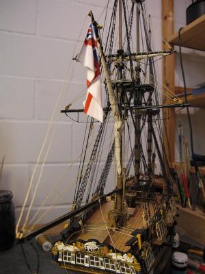
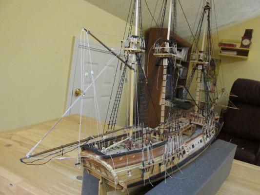
Peter, I was referred to your build log by Martin W with regards to the flag, specifically where the halliard is tied off to. I've been building the Rattlesnake for a while now (like six years) and have finally started the rigging. This is my first rigging so I am learning as I go. Although my kit is Mamoli, I also have Model Shipway plans. As it turns out neither one of them address where the flag halliyard is suppose to be tied. Looking at my book references, they basically state that it is tied off at the most convenient spot. My logic suggests it would be better to tie off on the boom so when the gaff and boom swing, the halliyard won't need extra slack or have too much. On your model, it looks like it goes to a deck or bulwark cleat (I can't tell). Was this your choice or were you instructed? What is the reasoning for attaching it there? Anything you can tell me to shed some light on this would be helpful. Thanks Jonathan P.S. That's a beautiful model you have created!
- 293 replies
-
- 1
-
-
- pickle
- caldercraft
- (and 1 more)
-
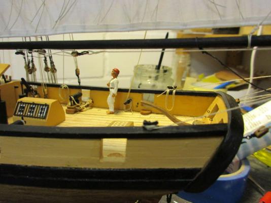
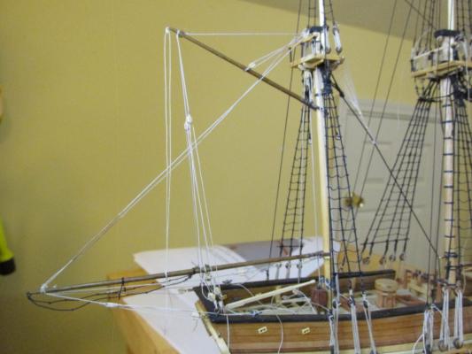
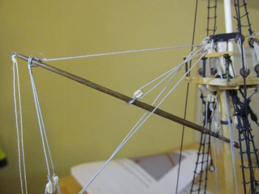
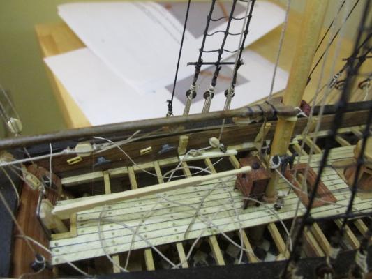
Installing the Gaff Boom Installing the gaff was very similar to the mizzen boom however there were a few surprises. The gaff halliard goes from the tip of the gaff through a double block strapped under the mizzen cap, back to a block half way down the gaff, up through the double block again, down to a deck block and ties off to a deck cleat. That double block should have been installed during the assembly of the mizzen mast as it was a real pain to strap it on at this point. Then I discovered that I needed to add cleats to the deck on each side of the mizzen mast for the gaff halliard tie off and the gaff throat halliard tie off (the line that lifts the gaff jaws). It turns out that I had added the cleats when constructing the deck but I placed them forward of the mast instead of aft. Because the deck was constructed to show the deck below, the area where the cleats needed to be was open so partial planks had to cut to fit. I also had to use the Syren cleats because I didn’t have any more kit cleats. I left the misplaced cleats in place. Another item that had to be installed, were the jeers to hold up the mizzen cross jack yard. These should also have been installed when it was easier when the mizzen mast was being assembled; but because I was/am a newbie to rigging, I didn’t know that. I know I will have the same and similar problems on the main and fore masts. At the tip of the gaff is a small eyebolt where the flag halliard block is attached. The Mamoli plans call for a 4mm block, the equivalent of a 10” full scale block. The MS instructions state “The halliards are single lines reeved through very small blocks on the gaff.” It does not indicate a particular block size. The MS instructions seem more reasonable; you don’t need a large block for a flag. I used a Warner Woods 2mm (5”) block stropped with sewing thread. From my research, since the instructions were not very precise, the flag halliard is a continuous loop and is tied off to the most convenient point so I chose the obvious point, the boom. If the flag halliard went to a cleat on the deck there would have to be enough slack rope to accommodate the swing of the boom and gaff. If the halliard were tied off to the boom the two would move in unison and no excess slack would be needed. I suspect the flag halliards are tied off to a small cleat on the boom but near set of plans address such a cleat. I could be totally wrong. For that reason I do not plan to add the flag to the halliard at this point for two reasons. First, somehow adding the flags seems like the final act of a model build and second, I’m not sure how it supposed to be done. For now, I’ll just tie if off to the boom with no flag. Any thoughts out there?
- 974 replies
-
- 10
-
-
- rattlesnake
- mamoli
- (and 1 more)
-
You might want also contact Model12, he made a real nice model of the Conny with a red stripe.
- 117 replies
-
- 3
-
-
- constitution
- model shipways
- (and 1 more)
-
With regard to the red stripe, the following came from Greg Meyer's build log on Knightdreamers.com: Using his method, you can still use regular masking tape. I hope this helps a bit. Jonathan
- 117 replies
-
- 3
-
-
- constitution
- model shipways
- (and 1 more)
-
Let me state first I have never made any rope; I purchase mine from Syren. I did however see a demonstration a couple of years back at an NRG Conference by Chuck Passaro as to how he makes that excellent rope. Believe it or not, he uses the cheap rope walk that Model Expo sells. He made one modification however: He motorized it by removing the hand cranks and adding (If I remember right) a Philips screw for a hand drill to turn at both ends. Once the lines were strung, he would fire up the hand drill and turn the mechanism at one end. Through trial an error he knew how far that end would move while keeping tension on it as the individual lines twisted and when to stop. Then he would go the other end and do the same thing. Because he was at the opposite end, the twist was reversed and that would twist the individual lines into one. He would then remove the newly constructed rope and pull it through some bees wax and he was done. He was able to knock off a twenty foot rope in less than 5 minutes or less. Rope length is determined by how far apart the two ends of the walk are. I haven't tried it yet because I don't need any more excuses to delay my build by experimenting and practicing rope making. I've been at it for at least 6 years now and still haven't finished. Jon
-
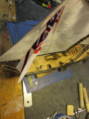
Ken did a hellova job with those transfers. It's hard enough to use them on paper with a flat surface and get them lined up properly, but on a curved surface in which you need extra hands just to hold the model steady while the transfers are rubbed on; outstanding! I should know, I used these transfers all the time in pre-computer days making custom made office forms. Jon
-
I found these white Roman number decals on HobbyLinc. - Gothic R.R. Letters -- White -- 1/16'', 3/32", 1/8", and 5/16'' -- Model Railroad Decal -- #mg721.(all on one sheet) Since I don't know how big the real markings are, I hopefully these will work.


