JSGerson
-
Posts
2,646 -
Joined
-
Last visited
Content Type
Profiles
Forums
Gallery
Events
Everything posted by JSGerson
-
 I don't have any other images of the brackets. I didn't realize the center one was different. I did however have some 1929 US Nay plans showing what the brackets looked like prior to the restoration. Believe it or not, they look like the bracket you already made! I also had some plans for the studding sail end and quarter irons. I guess the choice is yours Jon 25351-.pdf 25527 - Boom, Studding Sail, End and Quarter Irons.pdf
 -
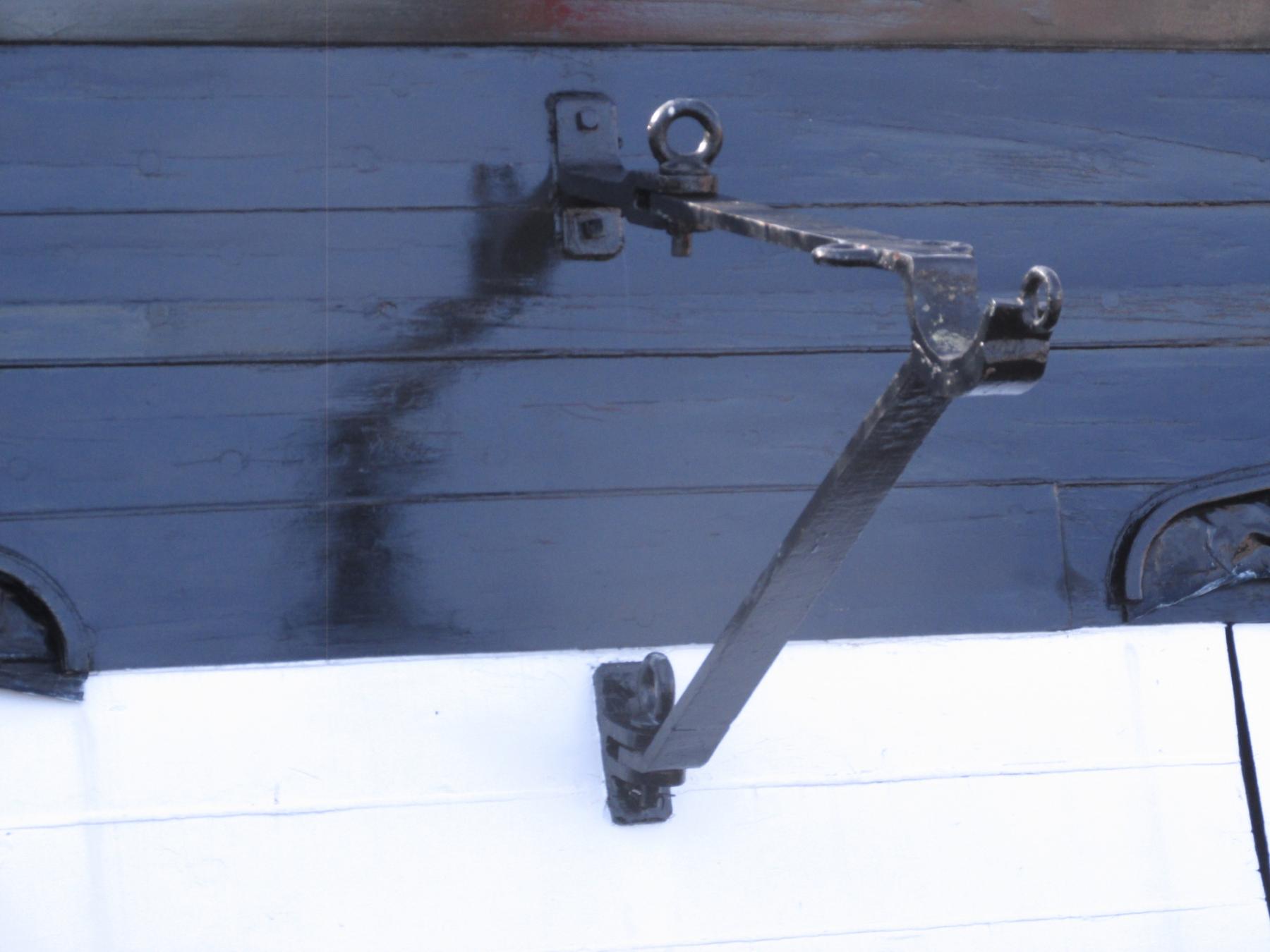
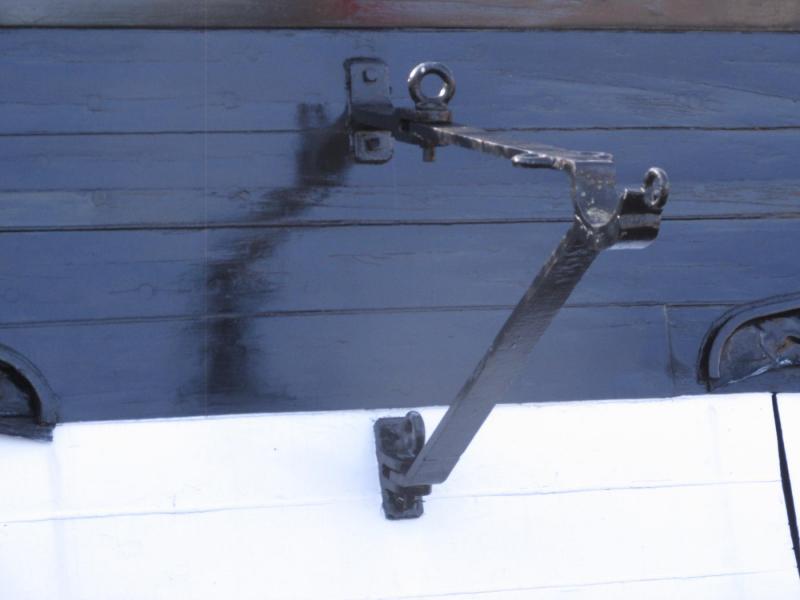
I just located an image of the studding sail boom bracket and I noticed that my image shows the two most external eyeloops are horizontal in orientation as opposed to the vertical ones you just made. Is that the way the plans show it? You are so meticulous, I wouldn't want you to make a mistake. Jon
-
When making the goose-neck brackets, you stated: "Layers separated and CA removed from both sides and surfaces sanded smooth." How exactly did you dissolve the CA? Did you soak them in acetone? If so, how did the solvent penetrate between the metal layers? BTY, have I mentioned before that I really enjoy your build log? Jon
-
At this point all that is left is sheet 9 of the Mamoli plans which is the rigging between the masts. But before I jump into that, I have to tighten up the existing rigging, clean up all the spaghetti, and add a bazillion rope coils. If I don’t do that now, the additional rigging between the masts will interfere getting to the inner spaces of the model.


- 974 replies
-
- 8
-

-
- rattlesnake
- mamoli
- (and 1 more)
-
The only thing worthy of note was that the top gallant halyards on the Main and Foremasts required a block in the mast tops as well as one on the deck. The lines go from the center of the yard, through the mast, and terminate at a block. The block starts a line which goes to a block on the top, back up again to the halyard block and then down to the deck block and finally belays on a mast cleat. Luckily, I had the forethought to pre-drill the holes for the eyebolt stropped blocks prior to installing the masts and the tops. The blocks were stropped to the eye bolt and then strung onto the line. It was just a matter of pushing the eyebolt stems into the pre-drilled holes.

- 974 replies
-
- 6
-
-
- rattlesnake
- mamoli
- (and 1 more)
-
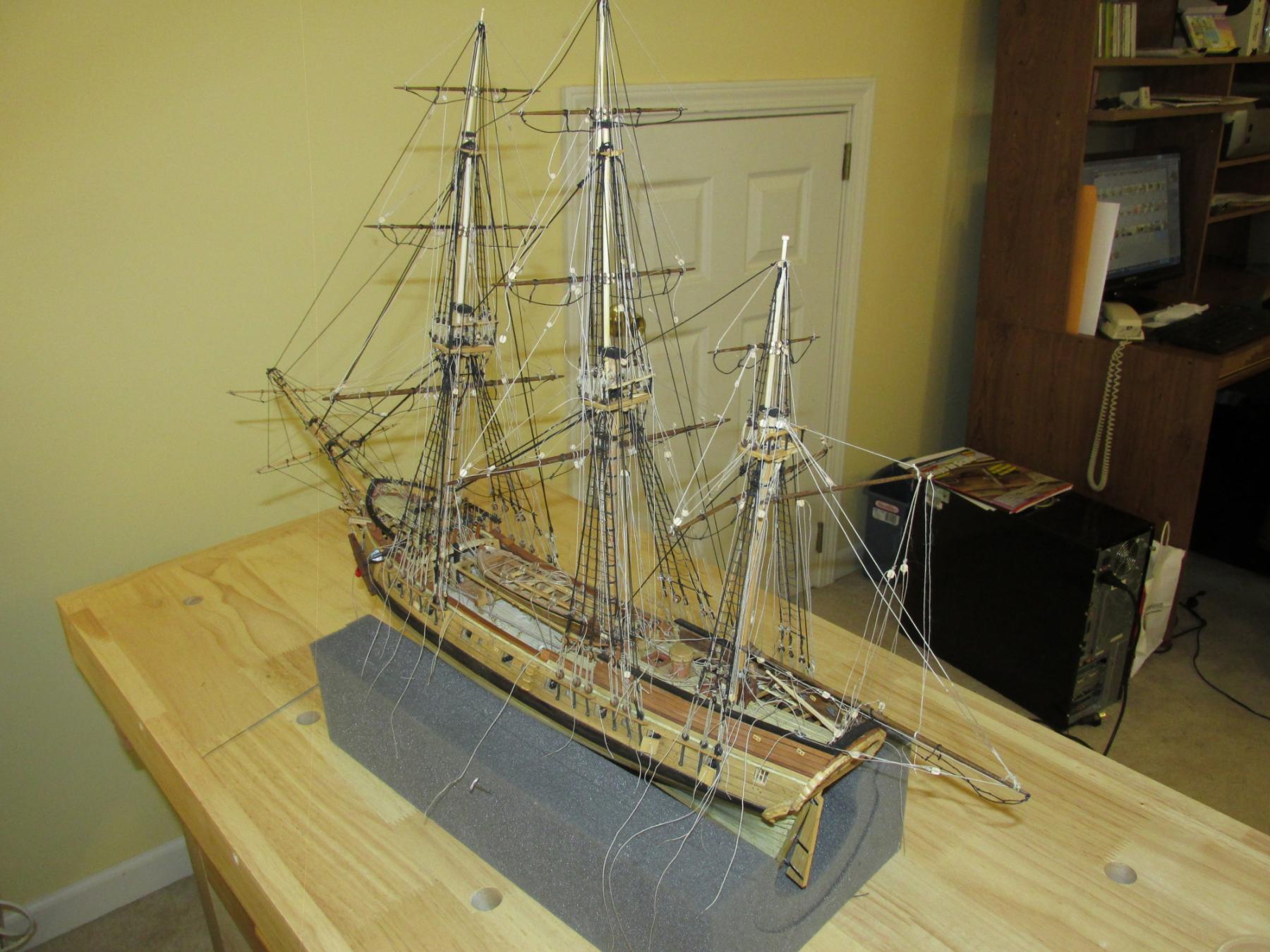
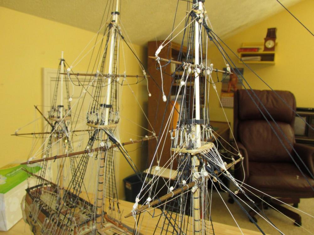
Another milestone: the last stick of wood (as far as I know), the fore top gallant yard has finally been installed. All of the rigging lines for the individual masts and yards have also been installed. Thank goodness because right now my model looks like a spaghetti factory run amok due to the fact that I left all the belayed lines with excess rope for finally adjustment.
- 974 replies
-
- 4
-
-
- rattlesnake
- mamoli
- (and 1 more)
-
Your model is looking real nice. At the beginning of your build log, you stated that you used my build log for the ship's boat so I assume you have also been following my Rattlesnake build log as well because I see you have anticipated some of the problems I've encountered and provided for them, A case in point are the shroud cleats - they are a lot easier to put on now then later. The Mamoli plans did not mention them. When I started my build, I had no experience with POB sailing ships, I had no reference books, I did not have the MS plans for clarifying details, among other things. I just plodded along using Hunt's practicum (which I highly recommend for newbies), learning as I went. I'm glad my errors, mistakes, and solutions have helped you. Jon
- 481 replies
-
- 5
-
-
- rattlesnake
- model shipways
- (and 1 more)
-
Where are you going to use Balsa strips? I'm curious, have you tried it on hard wood like boxwood or basswood? Jon
-
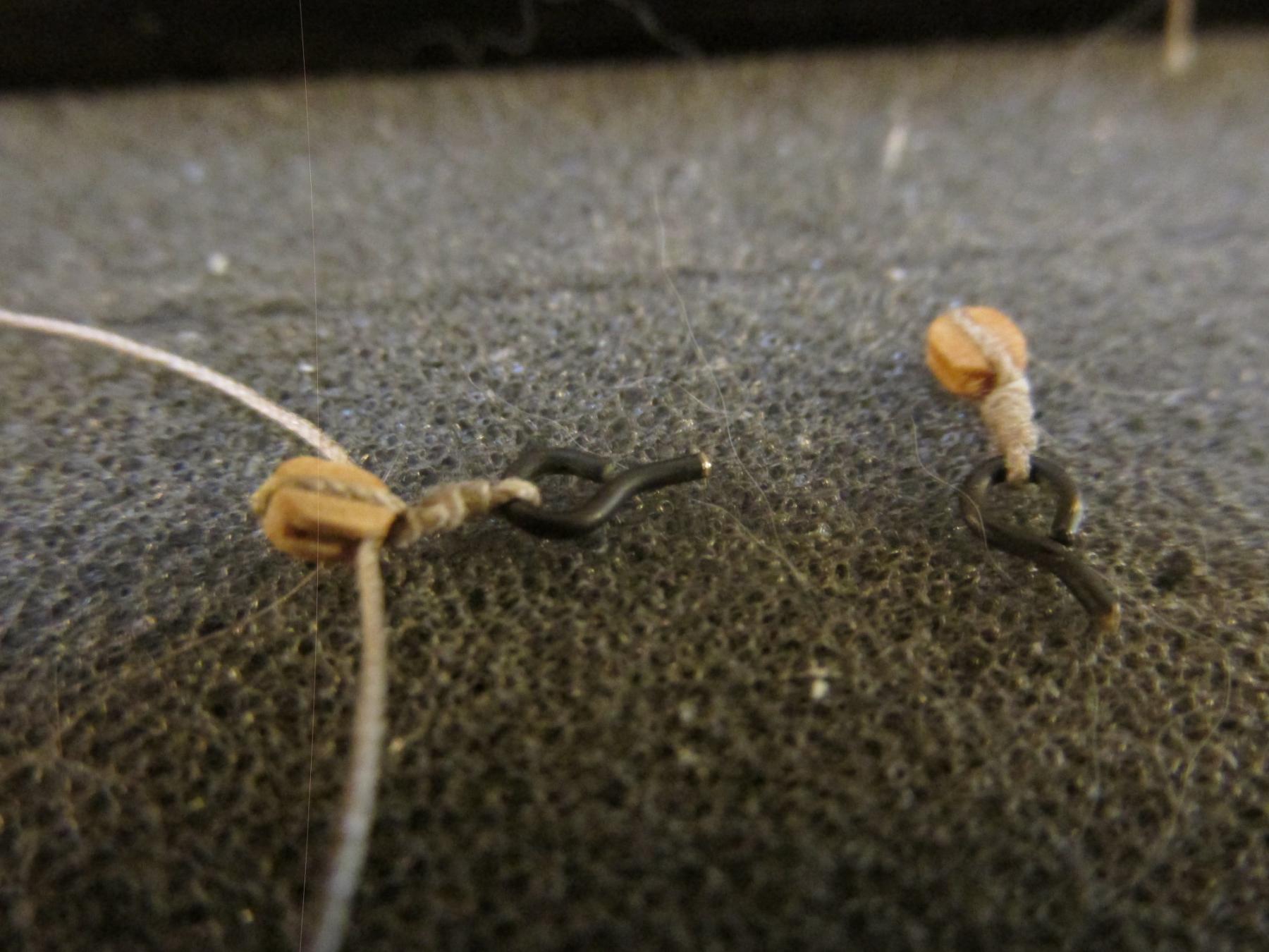
Scott - Those cleats were a bit tricky initially. I found that if I applied just a tiny bit of PVC into the grove I made on the backside of the cleat, it would hold the cleat in place. Because the cleats face inward, the PVC glue allowed me to maneuver cleat into position before the glue dried. Then I was able to tie fine thread through the center notch of the cleat and around the stay a couple of times. This would hold the cleat tight against the stay. No additional tying was necessary for mechanical strength at this point. But, since in the real world the cleats were also tied to the stays at their base "wings," I added those as well. Jon
- 974 replies
-
- 3
-
-
- rattlesnake
- mamoli
- (and 1 more)
-
I know absolutely nothing about fly fishing tools and therefore not a clue as to how they are used to make flies, let alone how to adapt them to ship building. Ken, if and when you obtain these "unusual" tools, please show us ignorant souls how it is done with your usual excellent flair for show and tell images. Thanks Jon
-
I'm not really complaining, just venting a bit. This is all new to me so each step is a step into the unknown. If I knew what I was doing, rigging wouldn't be so bad...tedious but not bad...I think. 8-)
- 974 replies
-
- 4
-
-
- rattlesnake
- mamoli
- (and 1 more)
-
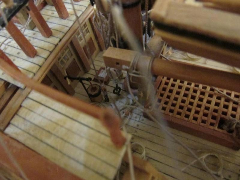
Other than going nearly blind trying to follow a single line as I install it through the mass of lines accumulating on the model, pulling out lines because they got twisted in some other line, or I terminated it at the wrong spot, progress is being made. I even took time off to visit Mom in Florida for a week. I won’t mention my fumble fingers bumbling into unseen lines and in some cases breaking them, trying to get some light into an area only to have my hands cast a shadow where I need to work. You know, the usual stuff… Oh, I guess I did. The sheet and clue lines above and for the main yards for the Main and Fore mast were completed once the topsail yards were installed. The sheet lines couldn’t be installed because blocks needed for them were suspended from topsail yards. Note: The Practicum called those clue lines but as I read it, according to Petersson’s Rigging Period Ship Models they are identified as sheet lines.
- 974 replies
-
- 11
-
-
- rattlesnake
- mamoli
- (and 1 more)
-
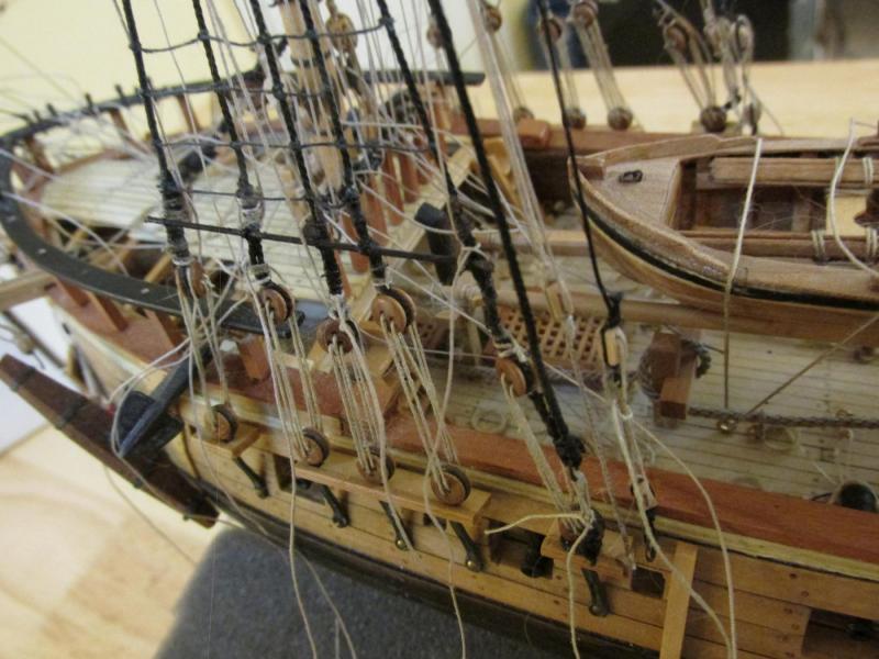
What I liked about the Mamoli rigging plans is that it breaks up the rigging so that you can see the different types of lines. One sheet shows the stays, another shows just the lines that hold and manipulate the yards, etc. as opposed to the MS plans which shows everything at once albeit the running lines are in red. I found the MS very hard to read with all the overlapping lines. Be that as it may, as hard as it is to understand what the lines are for, what they do, and where they go, plus how they terminate so I can install them properly (I’m a novice remember), the Mamoli plans threw me a few curve balls. On sheet 8 I found a least three errors. Now I am a very visual person, I tend to look at a diagram and build from that as opposed to reading the instructions (yes, I’ve gotten in trouble for that). Looking at the Mamoli rigging diagram seemed pretty much straight forward but the some of the items were mislabeled. After intense cross checking I think I’ve got it straight. The first one I’ve already mentioned, a kevel marked as 89A should have been No. 121 (This was also caught by Mr. Hunt in his practicum). The Main topsail sheet line was marked to terminate on shroud 326A. I could not figure out what the “A” stood for because Mamoli uses the nomenclature “Shroud Group # / line #” (e.g. 326/2°, shroud group 326 2nd line counting front to back)). As it turned, the line is supposed to terminate at bit No. 98A. Then I spotted the line for the Main Topgallant Sheet which was marked to terminate at shroud 326 / 1°. It should be shroud 326 / 4°. As it turns out, the printed rigging instructions detailing each line’s path on the plans was correct and was corroborated by the detail diagrams found on the detail diagrams. I wasn’t totally ignoring the printed instructions, but using them as a check list mostly to insure I installed all the lines. I guess I will have pay a bit more attention to those. If however, you look real close to the MS plans, one finds details not shown in Mamoli plans. One of these is some of the lines now being installed are required to terminate on the stays. On some of those stays, the Mamoli plans just indicate the shroud number and line as I just mentioned no explanation as to how they are tied off there. The MS plans indicted that shroud cleats were required. I used Syren’s 5 mm shroud cleats. They had to be finalized by carving the final shape and putting a concave groove along the back of the cleat. They were first glued into place with a very little dab of PVC glue and the tied at the side wings and at the center pre-cut groove.

- 974 replies
-
- 7
-
-
- rattlesnake
- mamoli
- (and 1 more)
-
Very well done!!! Jon
-
Glad to be of help. Your mini tutorials are going to be a great help to me when I start my attempt at the model. Jon
-
Are you building the 1812 version of the Conny? You might want to read the discussion on her windows and look at the images posted there of stern for reference. Jon
-
I don't have photos, but would the plans from the US Navy do? Jon 24422 - Spar Deck General Arrangement Taken from Work.pdf
-
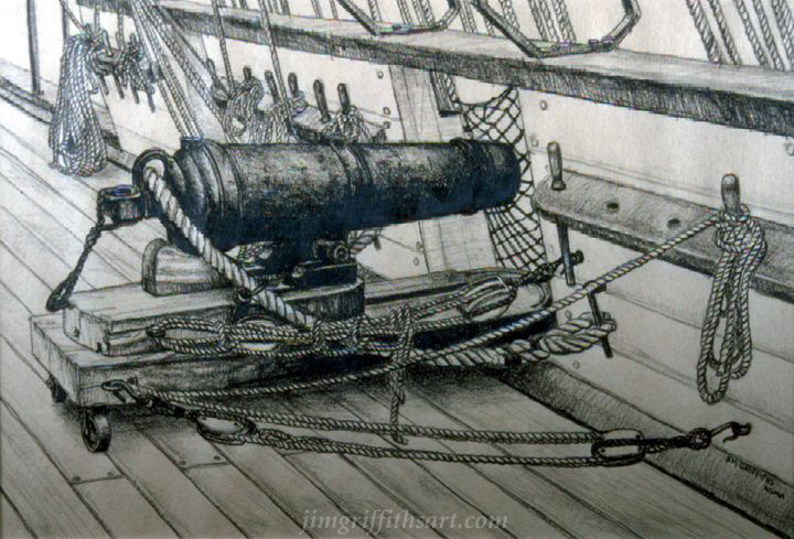
I did a search for another image of your cannonade picture and I did find one slightly larger as well as a drawing of a USS Constellation 32 pd Carronade by Jim Griffiths, a nautical artist. I hope these are of some help. Jon
-
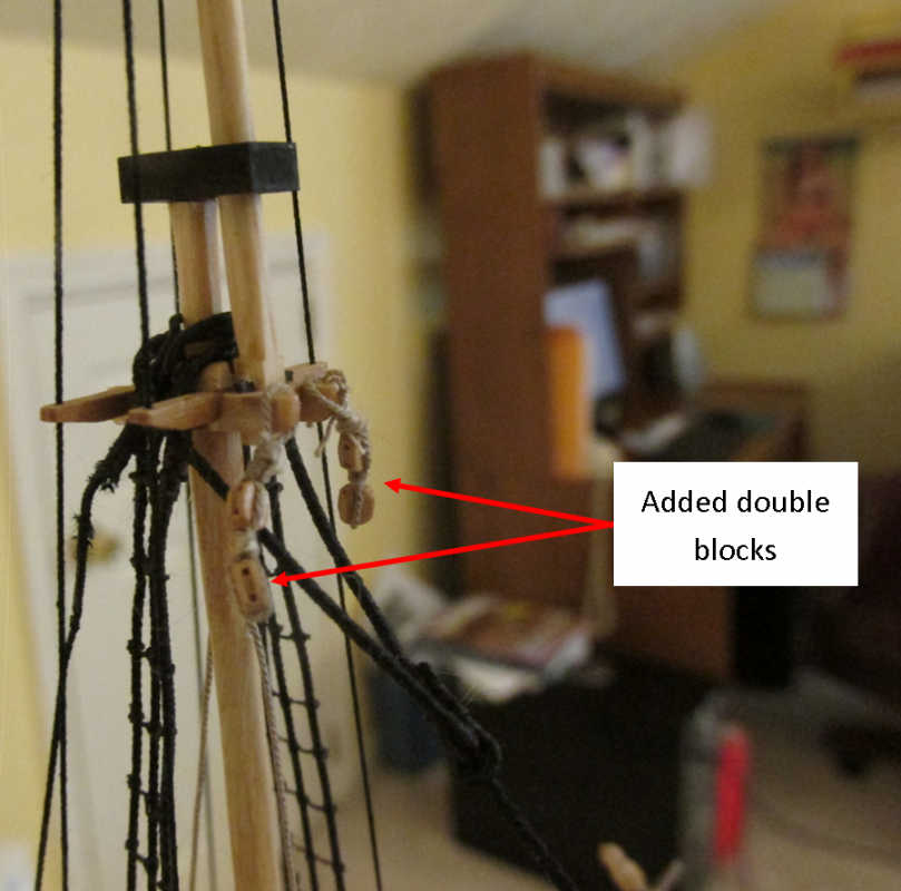
In order to rig the topsail yards lifts and halyards I had to first install double 3 mm blocks from the crosstrees (which should have been installed earlier, etc. but I’m repeating myself…again). BTY: When constructing the cross trees, both the Hunt practicum and the MS plans showed two “wings.” Those are the supports perpendicular to the beam of the ship. However, Mamoli ‘s plan showed two and three wings depending on which sheet of the plans you were looking at. I only noticed it now!!??
- 974 replies
-
- 8
-
-
- rattlesnake
- mamoli
- (and 1 more)
-
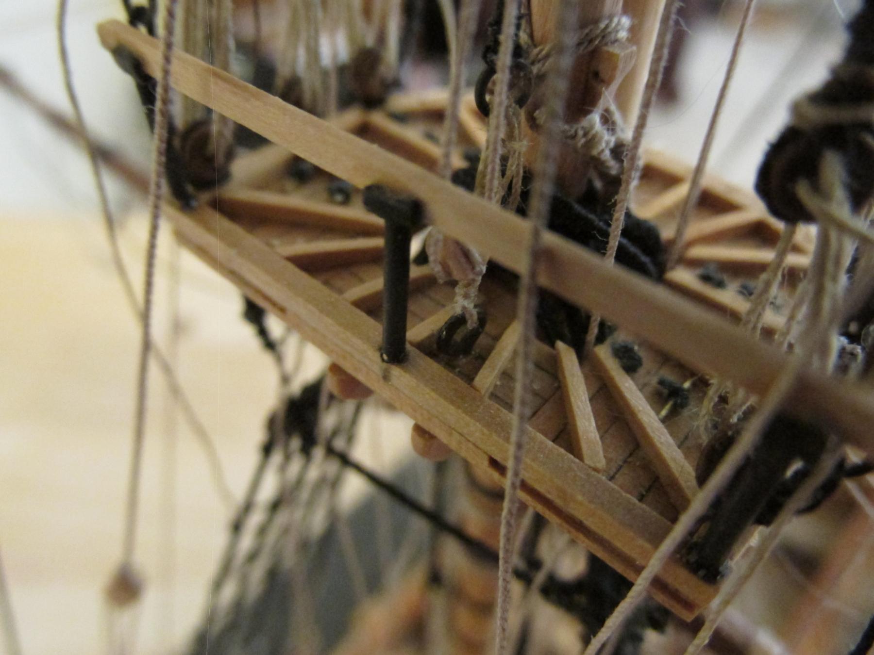
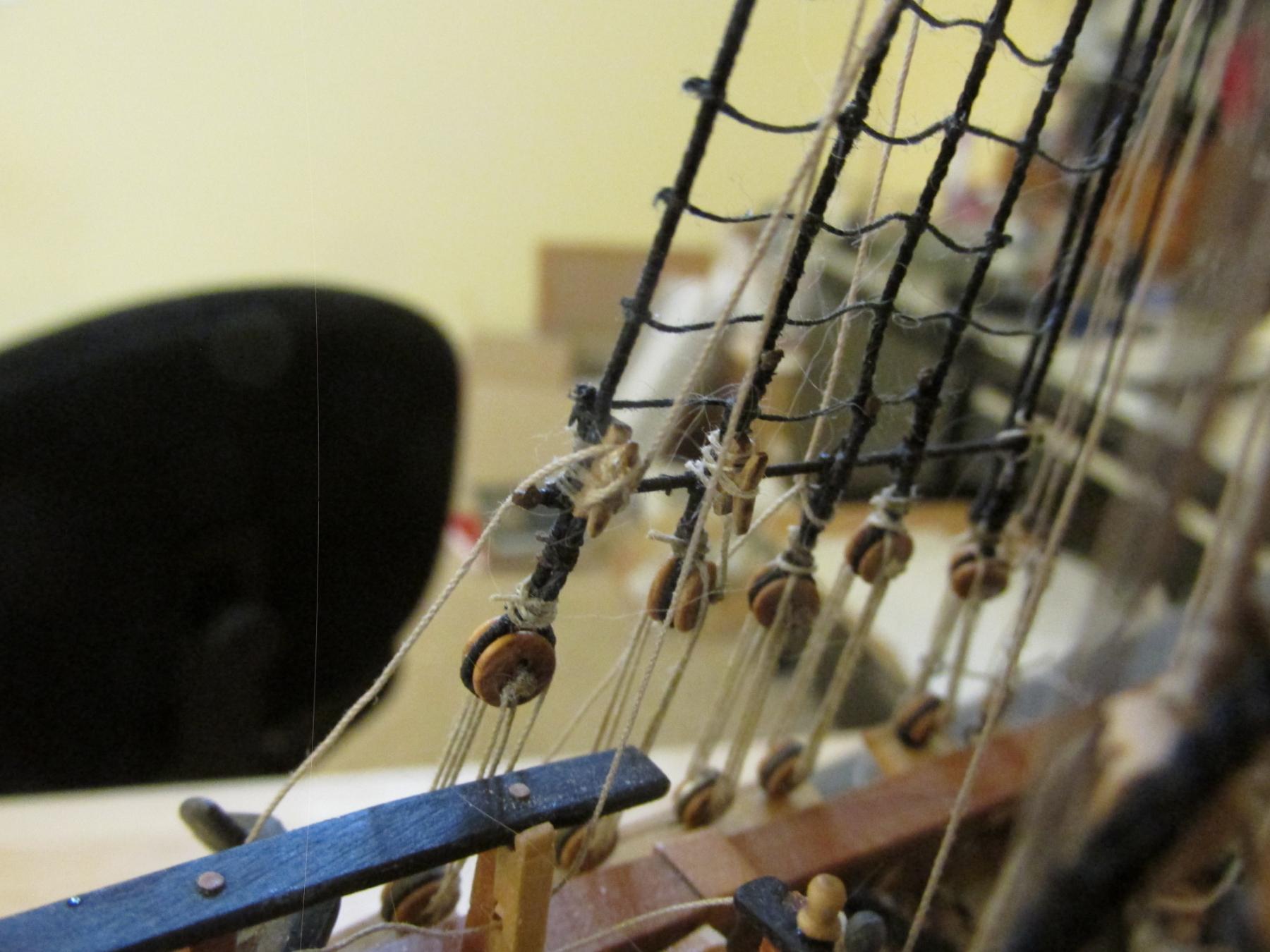
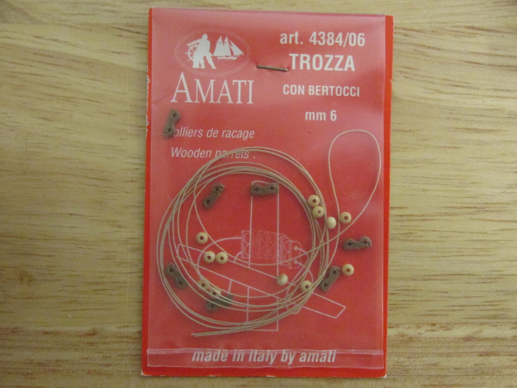
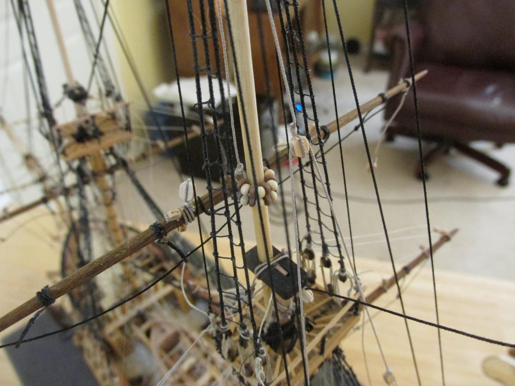
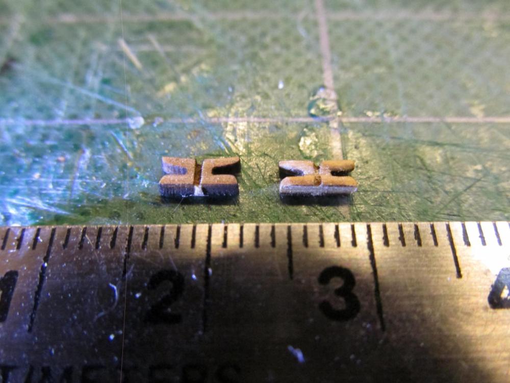
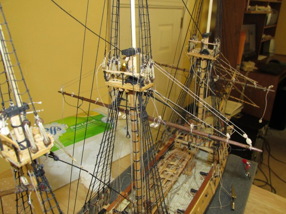
Topsail yards Before any more rigging could be installed to the Main yards, the Topsail yards had to be hung next. They were installed also in the same manner as the main yards but with a few differences. The Mains had two heavy lines through blocks each to suspend the yards. They also had lines wrapped around the yards to hold them against the masts which were tied down at the deck. The topsail yards were held with a single line that went through the mast and split into separate lines that went to the side rails through a series of blocks. To hold the yard against the masts, the Mamoli kit just looped rope around the yard and mast and lashed to ends together. The MS kit plans showed parrels. According to David Antscherl, the parrel ribs are 14” long or 5.5 mm at 1/64 scale. I chose to go with the parrels and used the 6 mm parrels (close enough) sold by Amati.


- 974 replies
-
- 8
-
-
- rattlesnake
- mamoli
- (and 1 more)
-
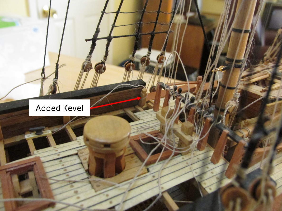
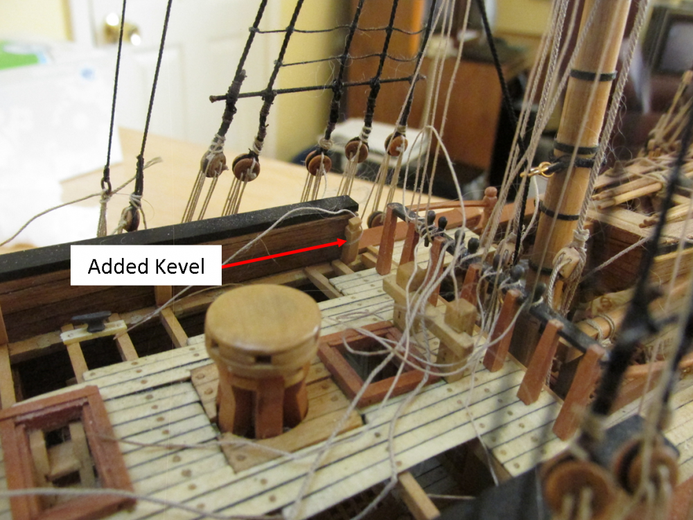
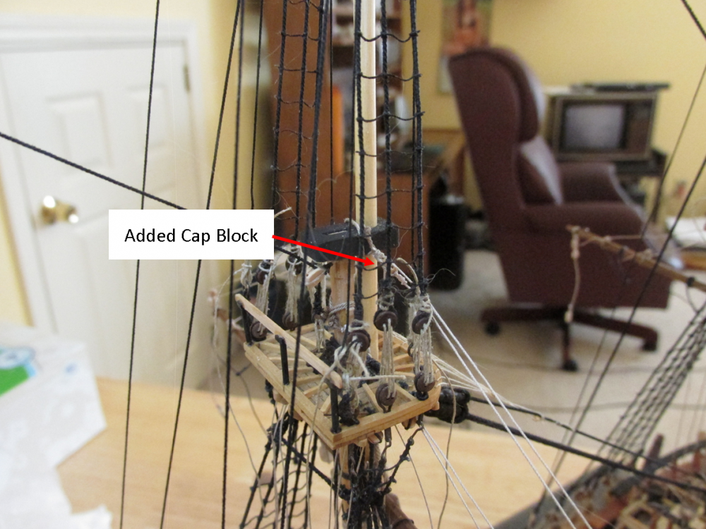
Mainsail Yard Lifts My first thought was to install the cross jack yard next and work my way forward to the main and fore masts installing their topsail yards. But checking the plans I decided to install the mainsail yard lifts first. Starting at the main mast, the 3 mm blocks that should have been installed when the masts were being assembled (am I being repetitive?), needed to be installed on the mast cap. They were a bit awkward to do, but they got done. The lift line went from the cap block just installed to the top block of the double blocks at the tip of the yard, back through the cap block and down to, through, and tied off at a kevel. The only problem - no kevels were installed in the location indicated on the plans. Back when I was following Bob Hunt’s practicum exclusively, he stated there were 8 kevels that needed to be made and installed. I did as he instructed, but he was wrong, there were 10. The missing kevels (Mamoli No. 121A port and starboard) located at the start of the aft upper deck had to be put in now. Not only that, but the Mamoli plan No 8 has an error – the diagram showing the front view of the main mast has the lift line going to kevel No. 89A instead of No. 121A. Kevel 89A is for the foremast. Making the kevels was no problem, installing them was quite another. Due to their location; I needed a pair of right angled tweezers due to the interference of the stays, ratlines and the inward lean of the bulwarks. Not like forceps, but more like a “Monkey” (Spanner) wrench concept. The closest I found is sold by Micro Mark. But even if I did have this instrument, I don’t think it would have done what I wanted in this situation. MicroMark Ear Polypus My first attempt resulted in disaster as I dropped the kevel and it fell into the bowels of the model never to be seen again due to the model’s open planking. Another kevel was made. My first attempt was made with CA glue which required a good flush contact immediately. That didn’t happen. My second attempt, I used PVA glue which allowed me to adjust the position once I made initial contact with the bulwark. The second kevel was installed was just as tricky but without incident. What really kills me is that I knew the kevels were missing for quite some time and could have installed them earlier and possible made my life a bit easier. I knew because while reading someone else’s Rattlesnake build log (forgive me, I’ve forgotten whose it was) this very problem was discussed. I failed to act on it quickly and it slipped my mind. The fore mast main yard and Cross jack were installed very similar. In hindsight, I could have hung the Crossjack first without any problems.
- 974 replies
-
- 10
-
-
- rattlesnake
- mamoli
- (and 1 more)
-
Since you are working on the hammock netting, here are two US Navy plans for the frame forgings. Jon 013-09-2009 - Forged Hammock Net Frame.pdf 19043001 - Hammock Stowagw Forgings.pdf
- 1,354 replies
-
- 2
-
-
- constitution
- model shipways
- (and 1 more)
-
That is some fancy display box! So now the question is: where are you going to display the model? I'm not thinking so much as in what room, but what does the box sit on to display the model? I've been wrestling with this problem in contemplation of the completion of my Rattlesnake. Jon
- 277 replies
-
- 2
-
-
- model shipways
- 18th century longboat
- (and 1 more)
-
Always a pleasure to read your build log. You mentioned you "used a technique described by Steve Wheeler in the January/February 2009 issue of Ships in Scale." I bought the CD archive of Ships n Scale and thought I was in luck because it goes as recent as 2009. Unfortunately I could not find the article you referenced. I searched the keyword oars and got zip. Searching for Steve Wheeler generated a lot of articles, but nothing stood out as the article on oars. Could it be hidden in some article on a different subject with a side reference to oars? Jon
- 277 replies
-
- 2
-
-
- model shipways
- 18th century longboat
- (and 1 more)