JSGerson
-
Posts
2,649 -
Joined
-
Last visited
Content Type
Profiles
Forums
Gallery
Events
Everything posted by JSGerson
-
 Thanks for the tip. How do you keep the rope together when you remove it from the jig? Is the "rope" coated, say with diluted white glue?
 -
I just caught you build today, beautifully done. I just caught some constructive criticism on my build of the Rattlesnake - my rope coils were/are sloppy [my term]. I really didn't pay too much attention to them. So my question to you is how did you achieve such nice results?
-
Igor (bdr449) - I did try to make perfect coils like you did without much success. So instead of going crazy, I assumed (probably wrong) that the "pretty" coils were used when the ship anchored, but during an actual sail, trying to keep the ropes that neat was a wasted effort. At least that was my excuse. How did you do your coils?
-
For the grating, I think you have two choices: Make them yourself, but you will need a micro saw like Byrnes or Peac Purchase them from a third party vendor If you have the saw, I'd give it a try but they are tricky. Every cut must be exact or it won't work. If you do it right, you can make a much finer grid than what comes with the kit and it will look nicer. If that fails then you can always buy.
-
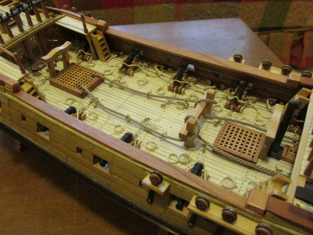
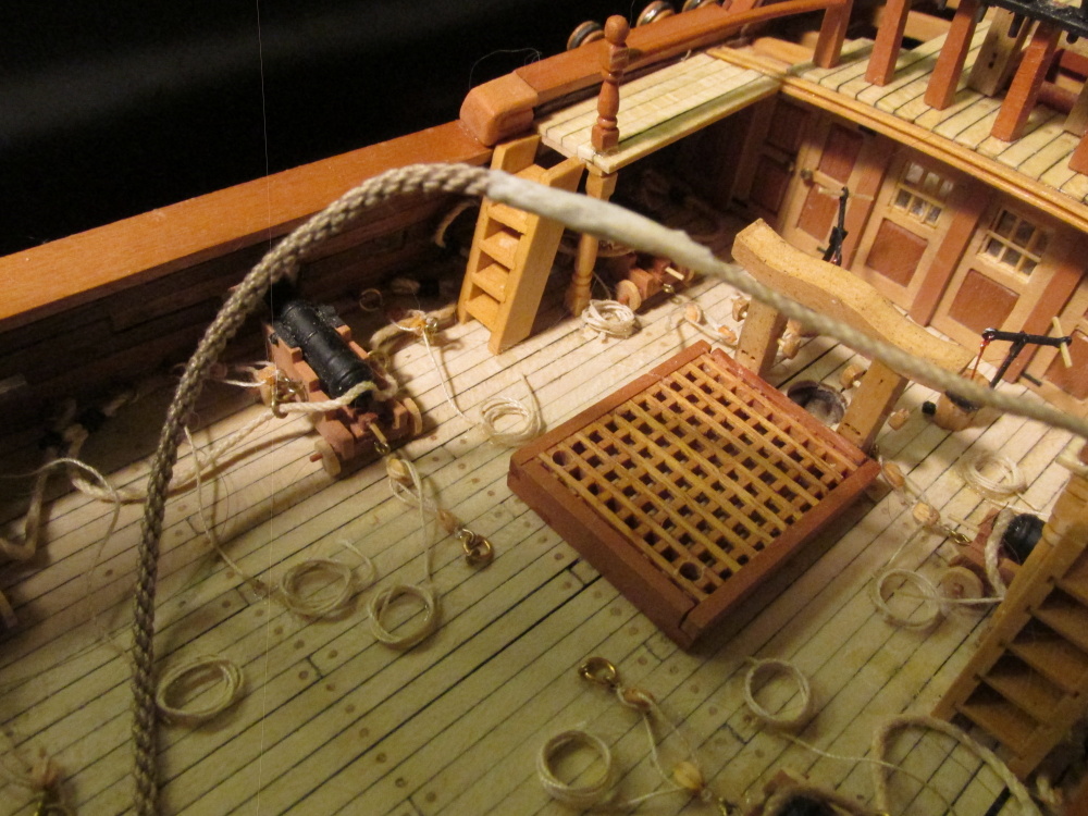
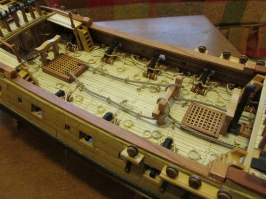
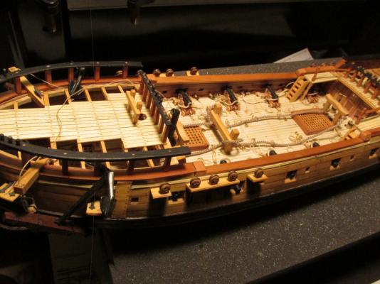
After the anchor rope passes through the deck rings it is fed into the main hatch. The Practicum instructed the builder to drill a hole through the grating with a 1/16” drill. The Mamoli plans show a square opening. Hahn’s plans are silent and his model is constructed in such a way that there are no gratings. The MS plan is ambiguous. The rope resolved the quandary. As soon as the rope is cut, it begins to unravel. Trying to keep it under 1/16” was impossible so I increased the hatch opening by cutting and making four grating opens into one. Now the rope had plenty of room to move during dropping and weighing anchor.
- 974 replies
-
- 1
-

-
- rattlesnake
- mamoli
- (and 1 more)
-
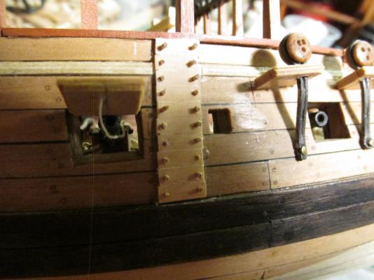
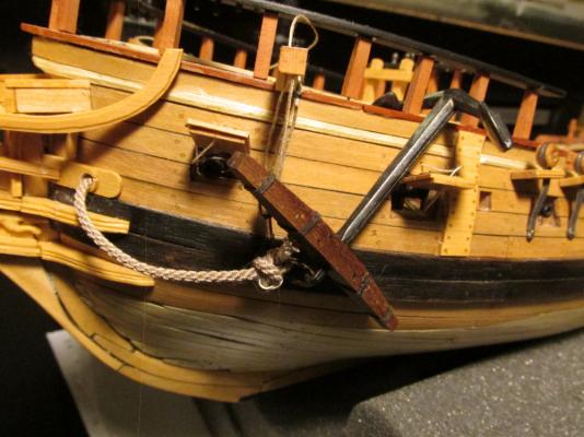
The Practicum does not address securing the anchor blade to the model although both the Mamoli and the MS plan show it. Mr. Hunt’s model does not appear to have this tie off. Both plans show an eyebolt in the deck from which a rope is looped around the anchor and tied off on the railing post. My model didn’t have the deck constructed where the eyebolt needed to be. Therefore a plank had to be added for the eyebolt complete with treenails.
- 974 replies
-
- 1
-
-
- rattlesnake
- mamoli
- (and 1 more)
-
There is a size restriction to the photos you can post. Maybe that is your problem. Check out this page on the site. It explains how to post pictures: http://modelshipworld.com/index.php?/topic/540-how-to-add-pictures-in-your-posts-and-pms/
-
Welcome bdr449. So glad that you like my blog. I hope that my successes and failures help you in your build.
-
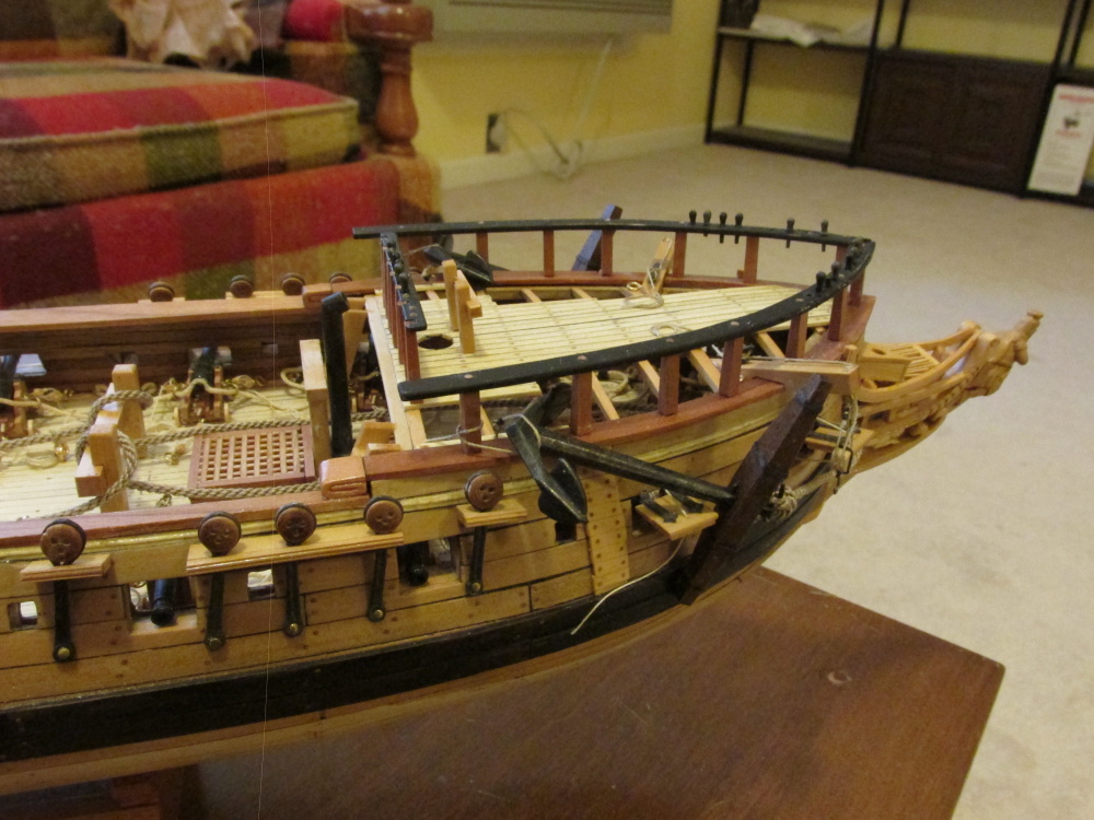
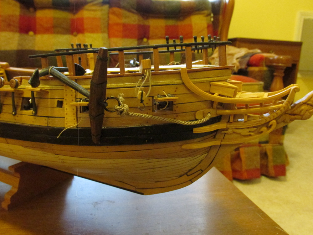
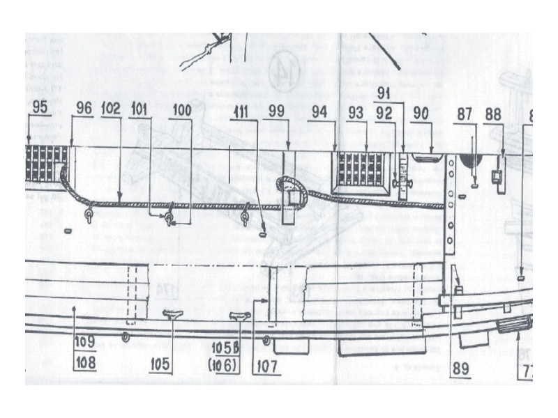
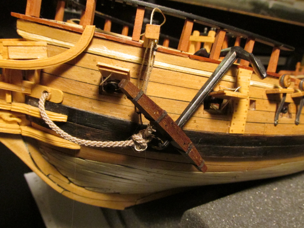
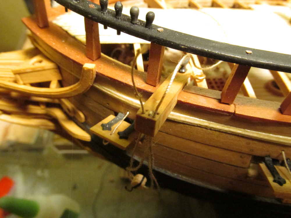
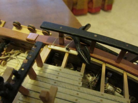
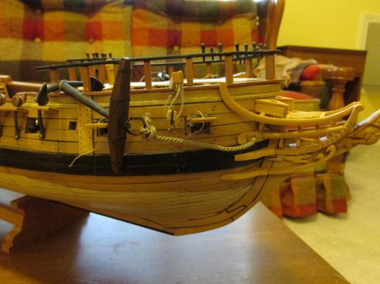
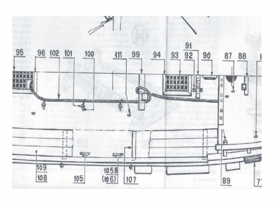
Looking at the anchor rope again I realized I made a couple of errors: I looped the rope incorrectly I discovered that I had installed the bitt backwards Per the Practicum, the anchor rope is simply looped over the outside of the bitt once. Per the Mamoli plan (the picture below), the rope starts under the inside of the bitt, comes up goes around the post and under the outside of the bitt. The MS plan is the same as the Mamoli except at the end it goes over the outside of the bitt. I chose Mamoli's method. It just seemed more secure. Is it right? I have no idea. The bitt was removed and reinstalled correctly. It wasn't until the rope rigging was questioned did I notice the incorrect installation. Here is what it presently looks like. Mind you, the anchor nor the anchor ropes are rigged in their final secured positions.
- 974 replies
-
- 3
-
-
- rattlesnake
- mamoli
- (and 1 more)
-
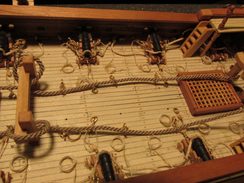
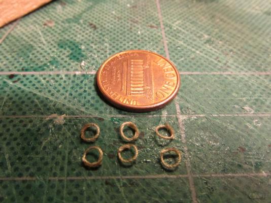
These were then strung onto the anchor rope and inserted into the deck. Once everything is in its place, the final details will be done.

-
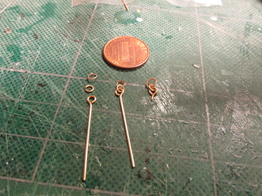
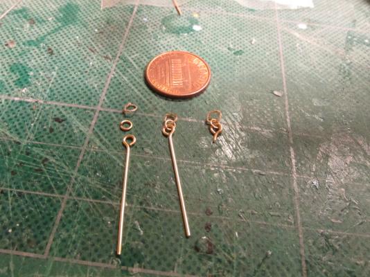
The rope ring and the deck eyelet were then attached to the metal ring and the eyelet was trimmed so it could fit into the predrilled hole in the deck.
-
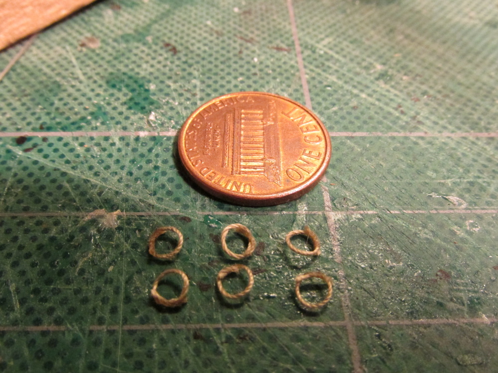
Once dried, the ends were trimmed off and I had my rope rings.
-
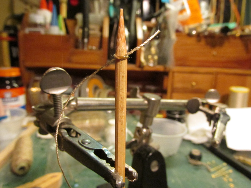
Per the Practicum the anchor passes through three rings imbedded in the deck. Both the Mamoli and the MS plans show the rope passes through a rope ring which is attached to another ring which in turn is attached to the deck ring. The Hahn plans are silent on this. To create the rope ring, which I assume in real life is a rope with its two ends spliced together, I tied a simple knot on a bamboo skewer (the same ones I used to make my tree nails) and put a small dab of CA glue where the lines overlap. The skewer just happened to be the same diameter as the rings I wanted to make.

-
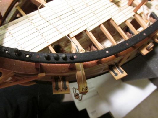
At the time I constructed the hawser openings, I did not have rope to test the opening size. As it turned out I needed to increase the openings by 1/32”. The anchor rope, by the way, I also bought from www.Syrenshipmodelcompany.com. Because of the close fit, I used a piece of string as a leader to thread through the opening and taped the anchor rope to it and pulled it through. It worked very well.

-
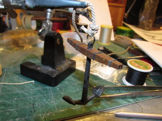
The anchor rope was tied to the anchor ring with an Inside Clinch after discussion with Blue Ensign on his HMS Pegasus build log. Thank very much for your input
-
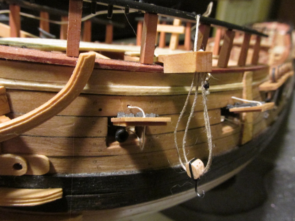
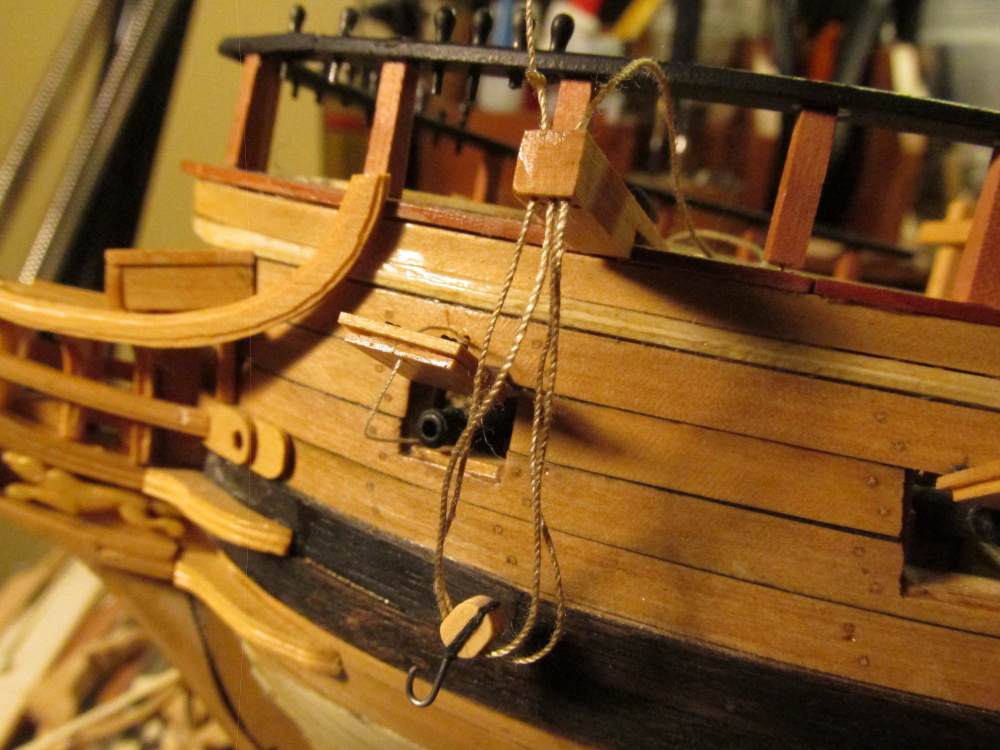
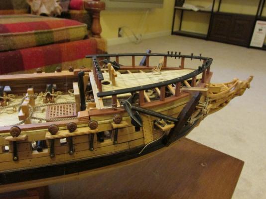
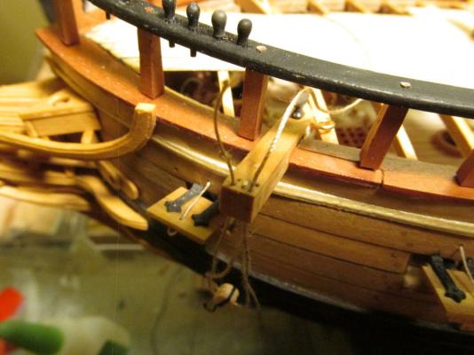
Well as it has been noted I made some mistakes when I installed the cathead rigging. The double block was installed 90º to the cathead sheaves when it should have been parallel. It was also pointed out to me that the rope should not have a knot as instructed by the Practicum but be started from an eyelet. These errors were corrected.

-
I've just discovered that I attached the blocks 90 degrees off. The block sheeves should be facing the same direction as the cathead's. Easy enough to fix, but I've run into another quandary - how is the anchor tied to the anchor rope? The Practicum uses a simple knot and seizing, the MS plans/instructions show a fancy seizing with no knot, Mamoli shows some sort of knot but does not describe, and others I've seen are a simple loop through the anchor ring and seized together. Anybody got ideas?
-
The blocks were then rigged to the cathead following the Practicum. Final touches await the addition of the anchors.
-
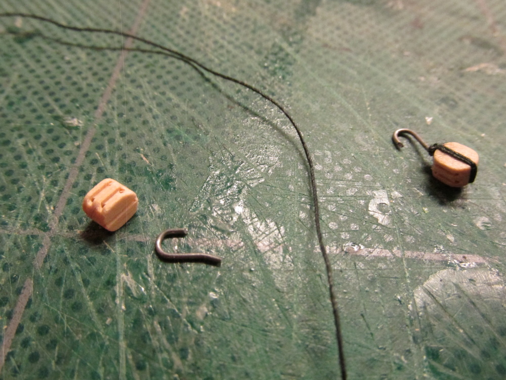
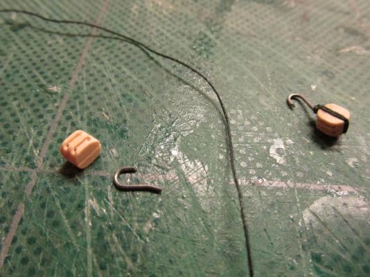
The blocks in this case needed a hook. The practicum stated: “I used some annealed black wire I had that was gauge.” Bob Hunt then bent the wire around the block and twisted it a few time to secure it. He didn't state what gauge he used. The Mamoli plans indicated that the hook was 0.5 mm. I had some music wire of various diameters and used 0.02” (0.5 mm). The music wire is the right color and strength but a bitch to bend especially at such small lengths. Instead, I drilled a hole in the block and inserted the wire in the shape of a hook and wrapped black thread as the stropping. It looked clean and at this size only the most discerning eye would notice. It is a model after all, not a miniature reproduction.
-
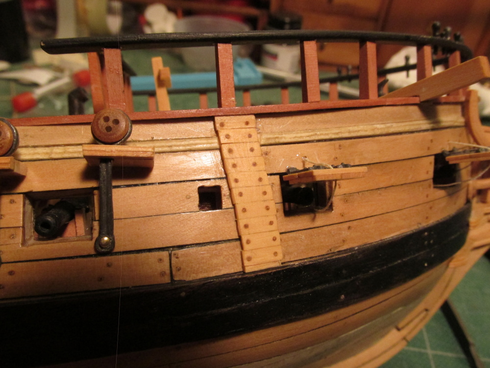
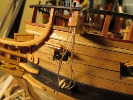
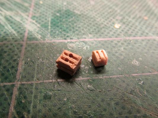
FYI I finally found out what the “reinforcing” planks are called. Per Jackstay, by Campbell they are called Billboards. “The word ‘bill’ in billboards comes from the tip of the anchor fluke which was called the Bill.” Installing the Anchor The Practicum called for a double pulley hanging off the cathead to lift the anchor into its stored position. The MS plans showed a triple block and the Mamoli plans showed a single block. The Hahn plans don’t address any detail about this. Well that makes it clear as mud. So based on other models, the consensus is a double block rigged the way the Practicum calls for it. So be it! The Mamoli kit obviously comes with blocks, the problem is they are bad; badly made, and bad to look at. Just compare these two double blocks. The one on the left was from the kit. The one on the right was made by Chuck Passaro’s company www.Syrenshipmodelcompany.com which, even at a smaller size, is superior in workmanship. All my blocks used on this model have been or will be supplied by a third party for this reason.
-
The anchor builds are based on Blue Ensign's build of the HMS Pegasus, a beautiful build chock full of goodies to contemplate. Thanks BE!
-
Great! How come you initially elected not to install them?
-
After the drying, the excess treenails were cut off, sanded, and finally coat of Wipe-on Poly applied.

- 974 replies
-
- 1
-
-
- rattlesnake
- mamoli
- (and 1 more)
-
Once the pieces were trimmed and sanded, the tree nails were drilled with a #70 bit. The tree nails were inserted and “glued” in place with Wipe-on Poly.