


JohnE
-
Posts
309 -
Joined
-
Last visited
Reputation Activity
-

 JohnE reacted to druxey in Greenwich Hospital barge of 1832 by druxey - FINISHED - 1:48 scale
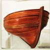
The roof of the coach has been completed and installed. As this is curved, a suitable strategy for building it is needed. I considered carving it from solid, but this would be difficult to keep a consistent thickness. I decided to cooper it, that is to say, build it up as one would a barrel.
The first step was to carve a form to build it on. I hollowed a piece of basswood to the appropriate radius, which in this case was 3½" full size (first photo). It was then shaped to the shape of the roof and marked out for the six planks that are nominally 1' 0" (scale) wide. These were cut and shaped with a slight bevel on each edge. They were then glued up on the form.
Once complete, two 'rafters' were glued on the underside to maintain shape and integrity. A piece of fine sandpaper was rubber cemented to the form and the upper side of the roof sanded (second and third photos). The outer side edges of the roof were sanded flat, to fit the coach top edges.
Following the color used on Prince Frederick's barge, I painted the roof a blueish green to imitate a verdigris copper roof. On the actual barge, the roof appears to be covered with painted canvas. I used a mix of viridian green, some white and then toned down with the addition of a touch of black. The top of the capitals on the coach were also painted this color and the roof glued in place.
Next is the decorative work at the stern.
-
JohnE reacted to druxey in Greenwich Hospital barge of 1832 by druxey - FINISHED - 1:48 scale
And... the coach sides and ends have been completed, the 'glass' installed and the four sides permanently assembled. After some fien adjustment, the corners came together quite nicely. For the statisticians among us, there were 53 separate parts required just for the outer surfaces of one coach side alone! Next, the coach roof.
-
JohnE reacted to mtaylor in Licorne 1755 by mtaylor - 3/16" scale - French Frigate - from Hahn plans - Version 2.0 - TERMINATED
Thanks for the comments and the "likes"...
Here's the rudder ready to hang. Once the cudgeons are on the hull, I'll add the rudder coat and mount it. I'll probably pin it to the sternpost from the inside of the hull just to keep it in place as I'll be flipping the hull over a few more times before cutting it loose and mounting it to a cradle.
I made a judgement call after testing on some scrap about the bolts. Not going to happen. If the bolts are visible, they're oversize by an order of magnitude. If' they're just the right size, they're invisible.
I also did some testing to compare Jax Black to Birchwood Casey Black. Not much difference except maybe the Birchwood Casey is a bit blacker and also seems to cover silver solder better.
Been a busy of testing this stuff.
Ok.. pictures.....
First piccy shows the old and the new together. I'm happier with the new and the old is hitting the scrap box. The second pic has a dummy sternpost next to it. I've got a big smile on that one.
-
 JohnE got a reaction from WackoWolf in Le Rochefort 1787 by Niklas - 1:36
Hi Niklas. I too will pull up a chair and have a nice pilsen beer. The rising wood looks beautiful. I am going to have to get one of your milling machines when I start on my ship. A wonderful toy.
Mike Y, the 'holes' are for mortice and tenon joints for the 'fourchettes' (crotch frames) aft. If you look close, you can see the rising wood has cut-outs on the top surface, but not on the sides like the middle portion does. To seat the very straight (approaching vertical) heels of the fourchette frames, the bottom edges of the frames faired directly to the outer edges of the rising wood and positioned by mortice and tenon, on center.
The hole could be round, or it could be rectangular; however the yard-dogs wanted to do it.
John
-
 JohnE got a reaction from uss frolick in Frégate d'18 par Sané , la Cornélie
Oh, golly, start in with l’estain and it just don’t quit (not that I mind, it’s just too legit).
Ok, then, top down view: fashion frame was two pieces (in effect, a couple), the fashion frame was itself but had a forward support frame. The heel of forward fashion support frame sat on, and flowed into, the aft frame of the aftermost ‘square’ couple set (Bourdiot’s FF). The heel of the fashion frame itself might be viewed as also flowing into the line of FF, but down at the bottom, everything flowed into the deadwood (le massif).
Notably, and unlike the station sections, the body plan line of the fashion frame (l’estain) is the after edge of the timbering (the red line). The body plan lines of station sections are taken from the center seam of the corresponding couple.
The position of FF, in the image, is totally arbitrary. Its actual location and individual timber thicknesses will depend on design definitions of frame, room and space, and what the yard dogs had for breakfast.
Anyway, this is the top-down view of the diagonals, based on everything else. The lines are now reconciled orthogonal to the other views. Please forgive my earlier attempts I was trying to replicate something that just didn’t fit within this paradigm. Sorry. I’ll get this into the plan set, as well.
John
-
JohnE got a reaction from uss frolick in Frégate d'18 par Sané , la Cornélie
Hi Bava. The outside red line on the halfbreadth of the profile file is the line of gun/main deck. The inside red line is the line of gaillards.I have a little problem with l'estain, too. I feel your pain.
Boy, oh boy; l’estain is a pain, yeah? Ok, some quick explanation. The fashion frame is simply a ‘cant’ frame, but expressed in the French fashion. It is ‘square’ in concept, but rotated aft by 20 degrees (or thereabouts). It was built super thick so that it could accommodate the compound (double twist) beveling from top to bottom (French were very profligate with wood).
Diagram shows two view directions and what they give. “A” indicates l’estain, if erected ‘square’. “B” indicates l’estain after rotation through 20 degrees. Curve “B” is what is projected on the body plan. It’s basically a lateral scale of cos(20) – 0.9397 applied to the ‘square’ curve. Curve “C” is the lazy ‘s’ curve of l’estain that appears on the profile plan. The profile curve is snipped at pertinent parts and the ‘square’ curve is scaled laterally by sin(20) – 0.34202. That pretty much reconciles the two orthogonal views (body and profile). I’ll make sure this gets done in the plan set.
Diagonals are another matter, entirely, and deserve a separate post with yet more illustrations and explanations.
This is good. I would have to have done something like this in explanatory text for the plan set, but this is a better venue and allows for better organization of the final views. Please do not hesitate to comment.
John
-
 JohnE got a reaction from Elijah in Le Rochefort 1787 by Niklas - 1:36
Hi Niklas. I too will pull up a chair and have a nice pilsen beer. The rising wood looks beautiful. I am going to have to get one of your milling machines when I start on my ship. A wonderful toy.
Mike Y, the 'holes' are for mortice and tenon joints for the 'fourchettes' (crotch frames) aft. If you look close, you can see the rising wood has cut-outs on the top surface, but not on the sides like the middle portion does. To seat the very straight (approaching vertical) heels of the fourchette frames, the bottom edges of the frames faired directly to the outer edges of the rising wood and positioned by mortice and tenon, on center.
The hole could be round, or it could be rectangular; however the yard-dogs wanted to do it.
John
-
 JohnE got a reaction from Niklas in Le Rochefort 1787 by Niklas - 1:36
Hi Niklas. I too will pull up a chair and have a nice pilsen beer. The rising wood looks beautiful. I am going to have to get one of your milling machines when I start on my ship. A wonderful toy.
Mike Y, the 'holes' are for mortice and tenon joints for the 'fourchettes' (crotch frames) aft. If you look close, you can see the rising wood has cut-outs on the top surface, but not on the sides like the middle portion does. To seat the very straight (approaching vertical) heels of the fourchette frames, the bottom edges of the frames faired directly to the outer edges of the rising wood and positioned by mortice and tenon, on center.
The hole could be round, or it could be rectangular; however the yard-dogs wanted to do it.
John
-
 JohnE got a reaction from tkay11 in Le Rochefort 1787 by Niklas - 1:36
Hi Niklas. I too will pull up a chair and have a nice pilsen beer. The rising wood looks beautiful. I am going to have to get one of your milling machines when I start on my ship. A wonderful toy.
Mike Y, the 'holes' are for mortice and tenon joints for the 'fourchettes' (crotch frames) aft. If you look close, you can see the rising wood has cut-outs on the top surface, but not on the sides like the middle portion does. To seat the very straight (approaching vertical) heels of the fourchette frames, the bottom edges of the frames faired directly to the outer edges of the rising wood and positioned by mortice and tenon, on center.
The hole could be round, or it could be rectangular; however the yard-dogs wanted to do it.
John
-
 JohnE got a reaction from druxey in Frégate d'18 par Sané , la Cornélie
Hi Bava. The outside red line on the halfbreadth of the profile file is the line of gun/main deck. The inside red line is the line of gaillards.I have a little problem with l'estain, too. I feel your pain.
Boy, oh boy; l’estain is a pain, yeah? Ok, some quick explanation. The fashion frame is simply a ‘cant’ frame, but expressed in the French fashion. It is ‘square’ in concept, but rotated aft by 20 degrees (or thereabouts). It was built super thick so that it could accommodate the compound (double twist) beveling from top to bottom (French were very profligate with wood).
Diagram shows two view directions and what they give. “A” indicates l’estain, if erected ‘square’. “B” indicates l’estain after rotation through 20 degrees. Curve “B” is what is projected on the body plan. It’s basically a lateral scale of cos(20) – 0.9397 applied to the ‘square’ curve. Curve “C” is the lazy ‘s’ curve of l’estain that appears on the profile plan. The profile curve is snipped at pertinent parts and the ‘square’ curve is scaled laterally by sin(20) – 0.34202. That pretty much reconciles the two orthogonal views (body and profile). I’ll make sure this gets done in the plan set.
Diagonals are another matter, entirely, and deserve a separate post with yet more illustrations and explanations.
This is good. I would have to have done something like this in explanatory text for the plan set, but this is a better venue and allows for better organization of the final views. Please do not hesitate to comment.
John
-
 JohnE got a reaction from PeteB in Frégate d'18 par Sané , la Cornélie
Reconciliation is going very well. I’m keeping extensive notes so when I have a senior moment, I can look up how I did something and why. So far, so good.
However, I note some inconsistencies in the buttock region of the diagonals of the half-breadth. They are due primarily to “angular projection” of the fashion frame, the periodicity and center of the last ‘square’ couple (after VIII, but before fillers) and, most importantly, the perspective “view”.
Buttocks of French ships are the least well described, and most often frustrating, portions of a model. French plans are rather inconsistent in their depiction of diagonal “view” as a function of other 3-space elements. Even the original sources, like Vial, pass it off. “Mediocrity will never do.” French had their own paradigms for plotting these lines, but that is of interest to historians. Model builders need something more substantive and determinative. So I went back to the well; back to the loaf of bread, actually.
Chapelle (and Wayne Kempson) put it succinctly; just slice a bread loaf. Slice along the plane of a diagonal and you get ‘options’. First of all, that plane is not orthogonal to any specific point. It is vertically skewed in accordance with the design rule, so the diagonal line will ‘project’ accordingly. If you do an accurate top-down view, accepting the angular plane-of-cut, you will get one set of curves. These will be ugly in the buttock region, and not in accordance with French practice.
Alternatively, once you get a diagonal “slice”, you can lay it down on the horizontal plane (making due allowance for stern to bow vertical shift). This gives another aspect to potential planking bend/flow in this critical area.
I know this isn’t how the French did it, neither did the English. But this is the best I can do to present the plans of a representative French frigate in a way that modelers can understand and reproduce.
Ok, so another half-breadth with another paradigm and buttock detail after VIII.
It seems like my life has zeroed down to massaging French buttocks. That’s ok ‘cause my Admiral is a Chillena and has the perkiest buttocks in the world.
John
-
 JohnE got a reaction from mtaylor in Frégate d'18 par Sané , la Cornélie
Reconciliation is going very well. I’m keeping extensive notes so when I have a senior moment, I can look up how I did something and why. So far, so good.
However, I note some inconsistencies in the buttock region of the diagonals of the half-breadth. They are due primarily to “angular projection” of the fashion frame, the periodicity and center of the last ‘square’ couple (after VIII, but before fillers) and, most importantly, the perspective “view”.
Buttocks of French ships are the least well described, and most often frustrating, portions of a model. French plans are rather inconsistent in their depiction of diagonal “view” as a function of other 3-space elements. Even the original sources, like Vial, pass it off. “Mediocrity will never do.” French had their own paradigms for plotting these lines, but that is of interest to historians. Model builders need something more substantive and determinative. So I went back to the well; back to the loaf of bread, actually.
Chapelle (and Wayne Kempson) put it succinctly; just slice a bread loaf. Slice along the plane of a diagonal and you get ‘options’. First of all, that plane is not orthogonal to any specific point. It is vertically skewed in accordance with the design rule, so the diagonal line will ‘project’ accordingly. If you do an accurate top-down view, accepting the angular plane-of-cut, you will get one set of curves. These will be ugly in the buttock region, and not in accordance with French practice.
Alternatively, once you get a diagonal “slice”, you can lay it down on the horizontal plane (making due allowance for stern to bow vertical shift). This gives another aspect to potential planking bend/flow in this critical area.
I know this isn’t how the French did it, neither did the English. But this is the best I can do to present the plans of a representative French frigate in a way that modelers can understand and reproduce.
Ok, so another half-breadth with another paradigm and buttock detail after VIII.
It seems like my life has zeroed down to massaging French buttocks. That’s ok ‘cause my Admiral is a Chillena and has the perkiest buttocks in the world.
John
-
 JohnE got a reaction from malachy in Frégate d'18 par Sané , la Cornélie
Reconciliation is going very well. I’m keeping extensive notes so when I have a senior moment, I can look up how I did something and why. So far, so good.
However, I note some inconsistencies in the buttock region of the diagonals of the half-breadth. They are due primarily to “angular projection” of the fashion frame, the periodicity and center of the last ‘square’ couple (after VIII, but before fillers) and, most importantly, the perspective “view”.
Buttocks of French ships are the least well described, and most often frustrating, portions of a model. French plans are rather inconsistent in their depiction of diagonal “view” as a function of other 3-space elements. Even the original sources, like Vial, pass it off. “Mediocrity will never do.” French had their own paradigms for plotting these lines, but that is of interest to historians. Model builders need something more substantive and determinative. So I went back to the well; back to the loaf of bread, actually.
Chapelle (and Wayne Kempson) put it succinctly; just slice a bread loaf. Slice along the plane of a diagonal and you get ‘options’. First of all, that plane is not orthogonal to any specific point. It is vertically skewed in accordance with the design rule, so the diagonal line will ‘project’ accordingly. If you do an accurate top-down view, accepting the angular plane-of-cut, you will get one set of curves. These will be ugly in the buttock region, and not in accordance with French practice.
Alternatively, once you get a diagonal “slice”, you can lay it down on the horizontal plane (making due allowance for stern to bow vertical shift). This gives another aspect to potential planking bend/flow in this critical area.
I know this isn’t how the French did it, neither did the English. But this is the best I can do to present the plans of a representative French frigate in a way that modelers can understand and reproduce.
Ok, so another half-breadth with another paradigm and buttock detail after VIII.
It seems like my life has zeroed down to massaging French buttocks. That’s ok ‘cause my Admiral is a Chillena and has the perkiest buttocks in the world.
John
-
JohnE got a reaction from PeteB in Frégate d'18 par Sané , la Cornélie
Ok, finished up the first pass at tweaking. Was reminded of what I have to do by something I saw on SawdustDave’s SoS thread quoting modelshipwright Bill. “Mediocrity will never do. You are capable of something better” – Gordon Hinckley. Darn good advice. I’ve been on Hinckleys.
There may be a few other tweaks, depending on what people find and how the buttock line sets project in 3D, but I’m comfy with this as a basic set of lines. Basic plans are 1:48, English/US measure; have gotten pretty good with scaling algorithms, so can also do Pieds du Roi, Pies de Burgos, or metric.
Now the fun/hard part begins.
-
 JohnE got a reaction from wrkempson in Frégate d'18 par Sané , la Cornélie
Ok, finished up the first pass at tweaking. Was reminded of what I have to do by something I saw on SawdustDave’s SoS thread quoting modelshipwright Bill. “Mediocrity will never do. You are capable of something better” – Gordon Hinckley. Darn good advice. I’ve been on Hinckleys.
There may be a few other tweaks, depending on what people find and how the buttock line sets project in 3D, but I’m comfy with this as a basic set of lines. Basic plans are 1:48, English/US measure; have gotten pretty good with scaling algorithms, so can also do Pieds du Roi, Pies de Burgos, or metric.
Now the fun/hard part begins.
-
 JohnE got a reaction from cog in Frégate d'18 par Sané , la Cornélie
Ok, finished up the first pass at tweaking. Was reminded of what I have to do by something I saw on SawdustDave’s SoS thread quoting modelshipwright Bill. “Mediocrity will never do. You are capable of something better” – Gordon Hinckley. Darn good advice. I’ve been on Hinckleys.
There may be a few other tweaks, depending on what people find and how the buttock line sets project in 3D, but I’m comfy with this as a basic set of lines. Basic plans are 1:48, English/US measure; have gotten pretty good with scaling algorithms, so can also do Pieds du Roi, Pies de Burgos, or metric.
Now the fun/hard part begins.
-
JohnE got a reaction from druxey in Frégate d'18 par Sané , la Cornélie
Ok, finished up the first pass at tweaking. Was reminded of what I have to do by something I saw on SawdustDave’s SoS thread quoting modelshipwright Bill. “Mediocrity will never do. You are capable of something better” – Gordon Hinckley. Darn good advice. I’ve been on Hinckleys.
There may be a few other tweaks, depending on what people find and how the buttock line sets project in 3D, but I’m comfy with this as a basic set of lines. Basic plans are 1:48, English/US measure; have gotten pretty good with scaling algorithms, so can also do Pieds du Roi, Pies de Burgos, or metric.
Now the fun/hard part begins.
-
 JohnE got a reaction from Canute in Les Bateux Leclerc
I looked them up. https://bateauxminiatureslucleclerc.wordpress.com/historique/ Apparently three generations of Canadian model makers. Models in several Canadian museums and the Queen of England is noted as having one.
Have no personal familiarity with the company and thus cannot comment on their model accuracy and the like, but can say that Les Bateaux Leclerc is legit. I would be comfortable purchasing their products.
John
-
JohnE got a reaction from druxey in Seeking information on determining load waterline
My friend, they used logarithms. They memorized the table of logs. A modern sliderule is nothing but a replacement for memorization. They used pen/pencil, paper, and their brains, along with a book of tables, if necessary.
This was the age of d'Alembert, Bernouli, Euler, Fourier, Laplace, Lagrange, Gauss, Rolle, and a bit earlier Newton, Descartes, and Fermat. Mathemeticians that we moderns are, frankly, unable to comprehend without an "advanced" degree; and it took 358 years to solve Fermat's last, the proof of which he declined to put in the margin because it was a 'bit' too long.
Don't ever make the mistake of thinking these people weren't "accurate" just because they didn't have computers or Exel. They had more practical math sense than I could ever hope to have, and I'm a physicist and naval architect.
John
-
JohnE got a reaction from malachy in Seeking information on determining load waterline
My friend, they used logarithms. They memorized the table of logs. A modern sliderule is nothing but a replacement for memorization. They used pen/pencil, paper, and their brains, along with a book of tables, if necessary.
This was the age of d'Alembert, Bernouli, Euler, Fourier, Laplace, Lagrange, Gauss, Rolle, and a bit earlier Newton, Descartes, and Fermat. Mathemeticians that we moderns are, frankly, unable to comprehend without an "advanced" degree; and it took 358 years to solve Fermat's last, the proof of which he declined to put in the margin because it was a 'bit' too long.
Don't ever make the mistake of thinking these people weren't "accurate" just because they didn't have computers or Exel. They had more practical math sense than I could ever hope to have, and I'm a physicist and naval architect.
John
-
JohnE got a reaction from mtaylor in Les Bateux Leclerc
I looked them up. https://bateauxminiatureslucleclerc.wordpress.com/historique/ Apparently three generations of Canadian model makers. Models in several Canadian museums and the Queen of England is noted as having one.
Have no personal familiarity with the company and thus cannot comment on their model accuracy and the like, but can say that Les Bateaux Leclerc is legit. I would be comfortable purchasing their products.
John
-
 JohnE got a reaction from rybakov in Seeking information on determining load waterline
My friend, they used logarithms. They memorized the table of logs. A modern sliderule is nothing but a replacement for memorization. They used pen/pencil, paper, and their brains, along with a book of tables, if necessary.
This was the age of d'Alembert, Bernouli, Euler, Fourier, Laplace, Lagrange, Gauss, Rolle, and a bit earlier Newton, Descartes, and Fermat. Mathemeticians that we moderns are, frankly, unable to comprehend without an "advanced" degree; and it took 358 years to solve Fermat's last, the proof of which he declined to put in the margin because it was a 'bit' too long.
Don't ever make the mistake of thinking these people weren't "accurate" just because they didn't have computers or Exel. They had more practical math sense than I could ever hope to have, and I'm a physicist and naval architect.
John
-
 JohnE got a reaction from trippwj in Seeking information on determining load waterline
My friend, they used logarithms. They memorized the table of logs. A modern sliderule is nothing but a replacement for memorization. They used pen/pencil, paper, and their brains, along with a book of tables, if necessary.
This was the age of d'Alembert, Bernouli, Euler, Fourier, Laplace, Lagrange, Gauss, Rolle, and a bit earlier Newton, Descartes, and Fermat. Mathemeticians that we moderns are, frankly, unable to comprehend without an "advanced" degree; and it took 358 years to solve Fermat's last, the proof of which he declined to put in the margin because it was a 'bit' too long.
Don't ever make the mistake of thinking these people weren't "accurate" just because they didn't have computers or Exel. They had more practical math sense than I could ever hope to have, and I'm a physicist and naval architect.
John
-
JohnE got a reaction from druxey in Frégate d'18 par Sané , la Cornélie
Boy, oh boy, talk about CAD being useful in design. I provided Bava, one of our forum members, with a scaled preview set of plans, so he could make a 3D model. Little did I know how interesting and valuable that would be.
The plans contained some vestigial curves that were used as design aids but were not strictly part of the “official” plan lines. I simply plopped in something and used them as starting points in the iterative process of refining and reconciling body lines vs waterlines vs diagonals in the all-important but not at all well defined stern/buttock area. However, since they were only aids and weren’t part of the official plan lines, I neglected to reconcile them.
Doing a hull in 3D lets one slice and dice it along any one of a multitude of planes. Stick in an unreconciled vestigial curve and it just doesn’t compute. Bava found two of those and let me know he had issues with them.
I fixed one (not used, but visually informative) and deleted the other (not used) and things are now fair and the lines correspond to each other in all 3 orthogonal views. Woof!
Going to have to turn on the obsessive/compulsive part of the brain and get perfectionist over every plan line regardless of its usefulness or ‘official’ character. Everything must be “correct” in 3 space.
Thanks Bava. Keep them notes coming. Cornelie thanks you, too.
John
btw: Христос Воскресе
-
JohnE got a reaction from rybakov in Seeking information on determining load waterline
There’s a lot of contextual stuff involved in this. Thought I might start with some thoughts on the 1690s and then post on the 1750s and beyond. I believe Jean Boudriot has slogged through the same stuff (and much more) and come the same conclusions; that this was inferential, subjective, and highly dependent on the coup d’oeil and skill of the designer.
Beginning with the 1680-90 period, There were “instructions” issued that set out rules, many of which had already been in use for some time. These “regulations” were cast as His Majesty’s desires, but one assumes they were articulated by the staff of Monsieurs Colbert, through Choiseul. The text includes the following:
“Two-decked frigates shall have as their greatest breadth outside plank (dehors des bordages) and at the midship bend (le maître), no more than a quarter of the length. … The depth of hold of the vessel shall be fixed at one half the breadth at the midship bend (le maître), counting from the keel to the “fix” point of the “span” of the gundeck (ligne du 1er pont), in a straight line. … With regard to the height of breadth, or breadth extreme (ligne du fort), His Majesty desires that it shall be precisely observed henceforth to place the height of breadth directly at the waterline (ligne de flottaison en charge).”
In 1680-90, French ships were built to a box rule of proportionality. Gundeck position was determined by the proportional mathematics of the rule. But the relative height of gundeck above ligne en charge and/or ligne du fort was determined by a “designer’s rule” as to how far off the water the guns were to be carried. Sill height above deck was given by the “regulation” so one simply moved straight down, from ligne du 1er pont, the requisite amount, and drew a horizontal line which became the reference for the load line (or line of max breadth).
They had a subjective appreciation of the problem, and the solution was practical, determinable and repeatable geometrically, although not particularly scientific. It was up to the designers to draw midship sections that would accommodate gundeck heights (from depth of hold values) and give a “ligne du fort” that accommodated a desired height of sill.
Given the extent of French proportionality and dimensionality rules for virtually everything else, I find the lack of anything related to waterline placement to be very significant. It infers that there was no generally accepted rule. His Majesty “desired” that the load and max breadth lines coincide, but this made no reference to different hull shapes. Clearly, geometric design wasn’t able to comport with reality at the extremes, so launching a vessel would very often result in either a loud “Bien” or a more subdued “Merde”.
Just my humble opinions.
John