Piet
-
Posts
3,568 -
Joined
-
Last visited
Content Type
Profiles
Forums
Gallery
Events
Everything posted by Piet
-
 First of all, thanks to everyone who visited and clicked "like." @ John (Lad): The large holes are presumed to be steps to climb up to the gun decks. The row of small holes I have also wondered about - - - I have no clue , I just follow the photos. Interesting question though. I understand there is a lavatory and shower inside that part and these small holes could be for ventilation. Don't hold me to it though @ Remco: Thanks for your confidence and I'll give it a honest try. @ Jan: Thanks for dropping in my friend and your kind words. Yes, I keep plugging at it and it's still going slow, to my thinking. Thank you for the holiday wishes en wij wensen jouw en je familie ook prettige feestdagen toe en een zeer voorspoedig Nieuw Jaar. Okay now, everybody say,"what d'he say??? " I just wished John and his family joyful holidays and a prosperous New Year. This goes for everyone. @ Popeye: Thanks my friend and now I understand what you meant. Yes, I used the right way of the grain, it bends okay. I need to make one more bend like that for the cockpit - - - sorry for the airplane talk - - - not really - - - har, har, har I'll be working these four outside steps in from the backside. It's a little (a lot) more work but will look much better that way. The larger holes have support on the inside. Yes, doll house hinges are much too big and like I mentioned in yesterday's post, Santa brought me some super small brass tubes of 0.5 mm. This should answer Jan's question too Also happy holidays to you and the Admiral. @ John (Texxn5): Thanks John and yes, the superstructure was not very high up, no need for that in that era. The latest diesel electrics are also a far cry from what these boats were. They can also stay submerged for long times. Cheers,
 -
Ah - - - a face with a name! Model is looking great and have a great holiday season. Stay in good health! Cheers,
-
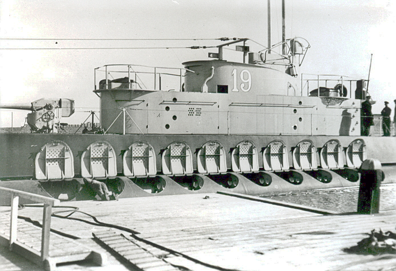
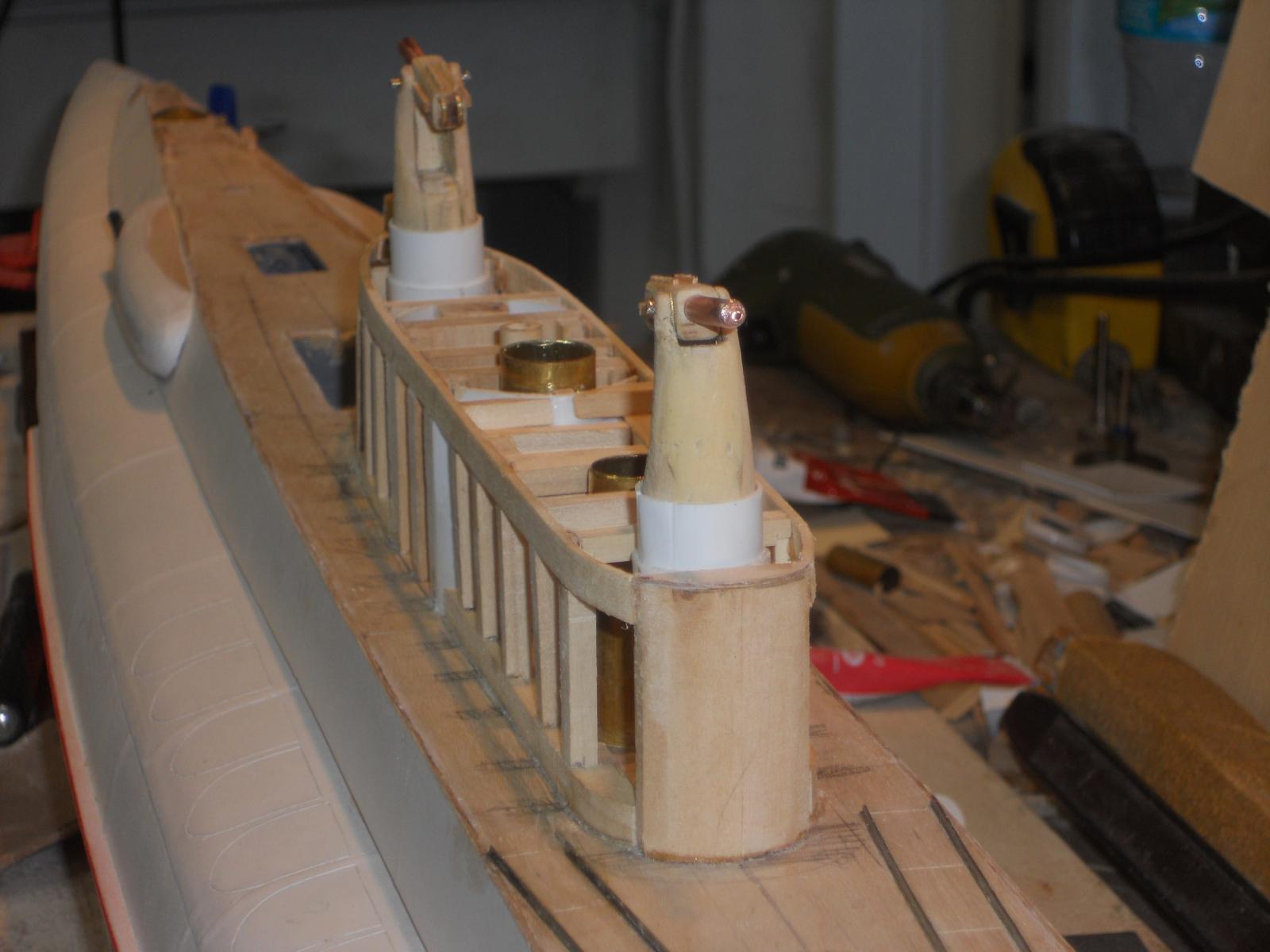
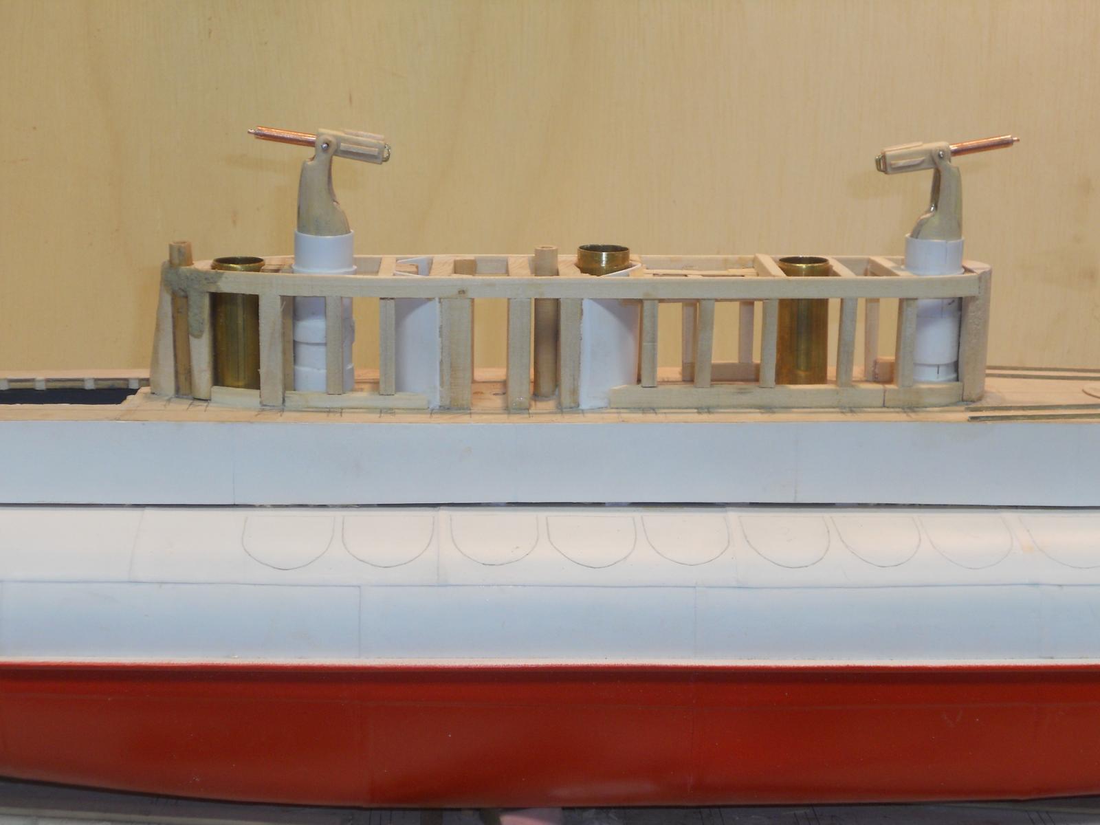
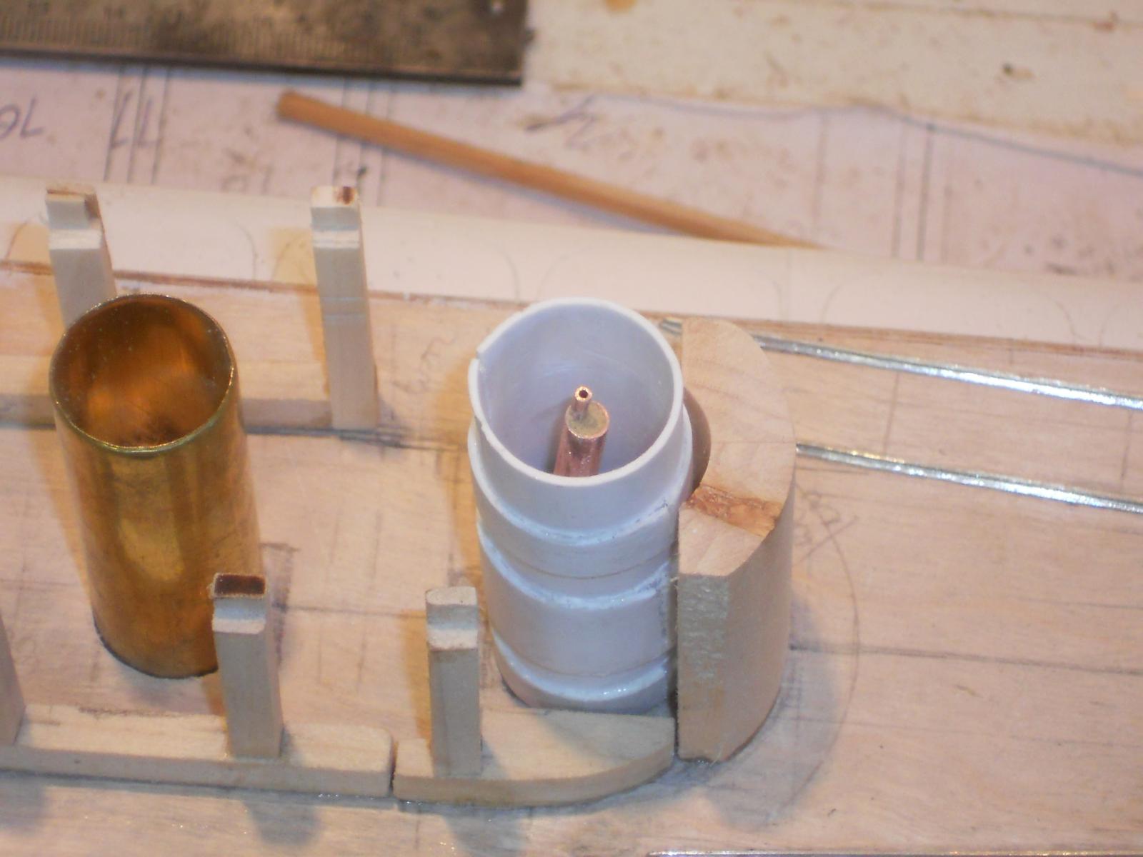
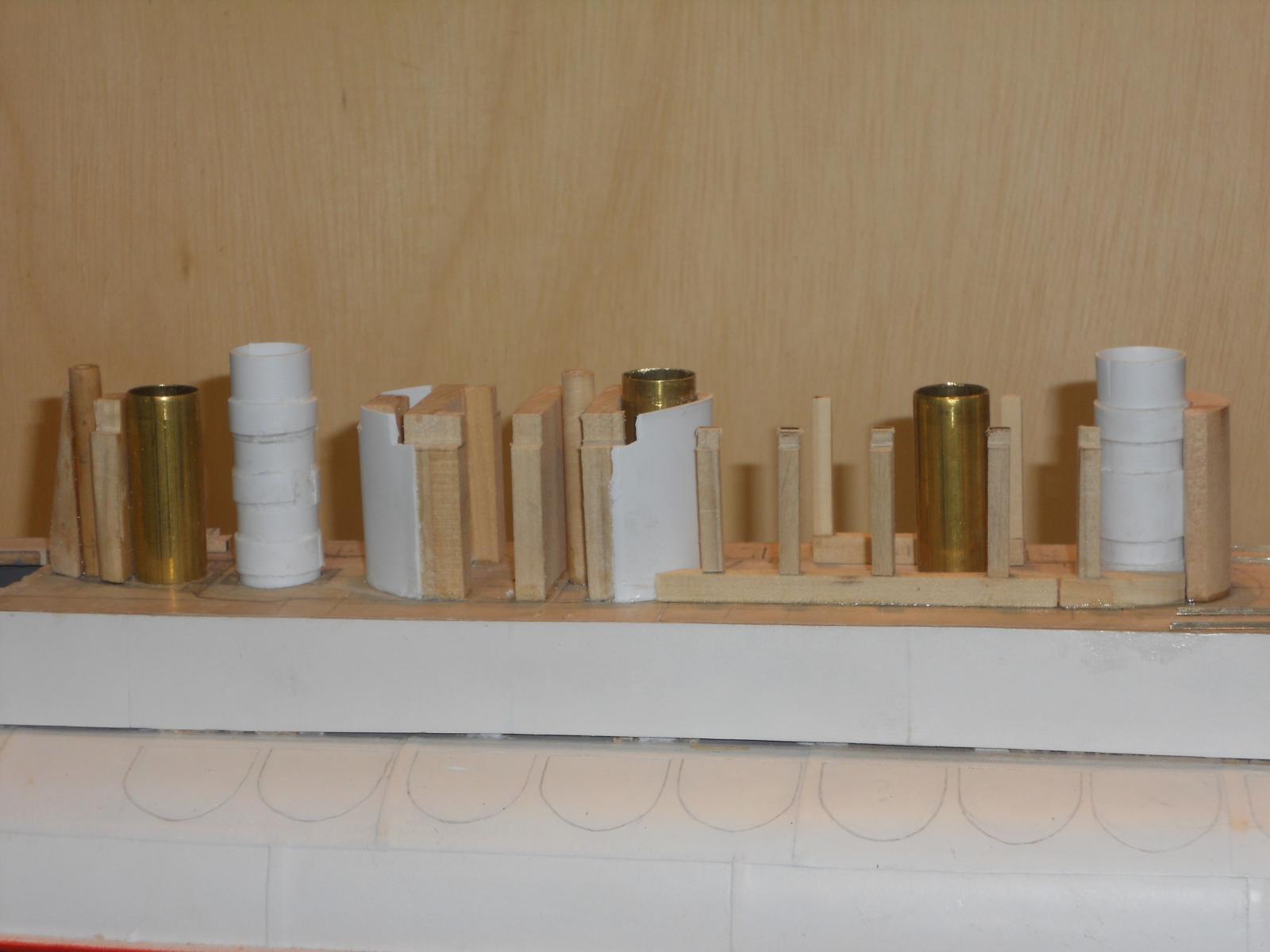
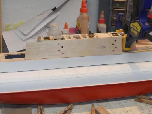
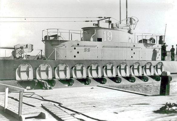
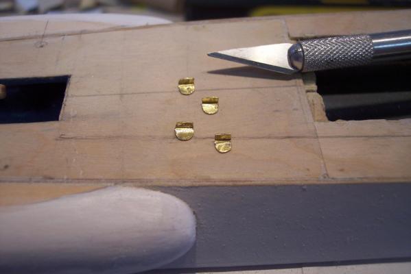
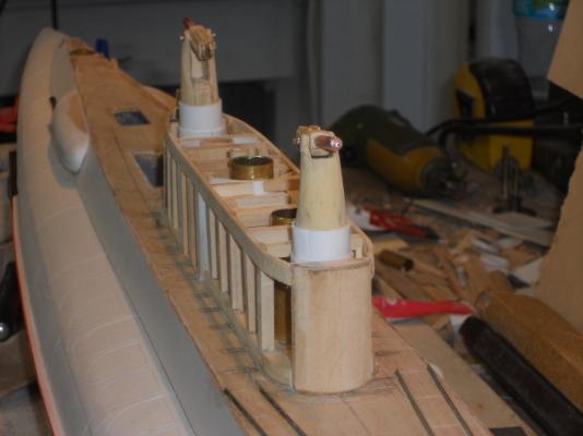
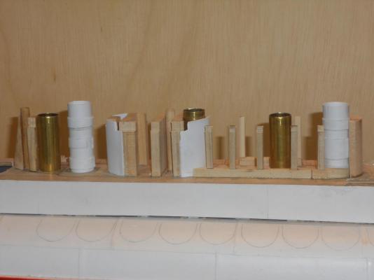
Today I made some more progress. I fiddled with the guns a little more in cleaning them up and then trimming some here and there to make them move in and out of the buns. The added thingies on the top were giving me a little problem but trimming a few thou off they slid in fine. I may have to cement these styrene tubes to the frames to keep them in place, the guns are just a tad snug, which is a good thing but it may lift the tubes out. This too is no problem because they can easily be put back in place. I made and installed the cockpit deck, that's where the commanding officer or whomever is on watch stand. The KM (Koninklijke Marine - Royal Navy) submariners call it "de badkuip" or the bathtub. I may as well make and cement the styrene deck slats to it while its nice and accessible. (Note to self: buy a tube of green Testor's cement - - - thanks Popeye). I cut out and glued the front part to the lower con from 1 mm plywood. It's still in the clamps to let the glue cure. In the meantime I cut out the starboard side panel and cut the step holes in it already. It would be more difficult after it's glued on. After this side is done then we'll turn the build board around and work on the port side. There is more detail on the port side, three doors! Hmmmm hinges - - - Saint Nicolas gave me some REAL small brass tubes and pins for hinges and now I'm really scared to try I'll need a 10 power magnifier to see the little buggers. Well, that's it for today below are a few pics but without the AA guns, they are resting in the "completed" section. This shows the rough precut starboard side panel. The curved front part is in clamps to let the glue cure. There are four outside foot supports at the aft end but they have oval holes in the side panel. These holes will be made tomorrow but I think to glue the steps on after the panel is installed. Even CA glue doesn't hold very well to this plywood. I may have to scrape some off. To give you an idea where the steps are I have added this picture of the real boat. You can also see that this lower con part is really not very high. This shows the four metal outside steps at the aft end of the con. Hmmm - - - looking at the picture I need to do some trimming. Yes, they show bottoms up. Cheers,
-
Thank you all for visiting and your like votes! @ Mark: Thank you for your kind words, appreciate it and the Admiral and I wish you and yours also a great Christmas. @ John (texxn5): you are welcome and thanks for your encouragement and kind words. Yeah, the end of this project - - - I'm also looking forward to it but I am taking my time. @ Sailor: Thank you too for your kind words. keep watching @ Sjors: Thank you Sjors - - - hmmm, skills - - - well it all started a long, long time ago, in a country far, far away - - - Oh sorry, that's another story Technical schooling and over 60 years learning while working for a living, aka the school of hard nocks Can you translate that gibberish stuff for me??? - - - me no habbla Dutch anymore after living in the USA for 56 years I'm kidding of course but the funny thing is that I speak Dutch with an American accent, go figure. "Prettige Kerstdagen en een zeer voorspoedig 2014 voor jouw en Anja." @ Augie" Thank you my friend, and we also wish you and yours the best of holidays. @ Popeye: Yeah, it helps in "nailing" the side panels on The side panels as well as the decking is 1 mm plywood. No grain because it's supposed to simulate steel sheet. The side of the plywood that faces out is extremely smooth and with the primer sanded down it really is as smooth as a baby's rear The Testor's red works fine. I first tried it with a piece of scrap on wood and it sticks real good. It was what I had left over from way, way back, when I put a plastic model of a PBY together for a small museum. But thanks for the tip of the green Testor's, I'll go get a tube when I'm glueing the deck strips on. I don't know yet if I'm adding more detail to the guns. These last additions caused me some work because it all has to fit inside the tubes, there is very little space to spare now. I'll have to see - - - To all of MSW, especially my visiting friends, the Admiral (Gwen) and I wish all a very enjoyable holiday season. Cheers,
-
Excellent! Short and sweet. This is a very welcome addition to submarine kits, there are just not may of them. I wish you good luck with it. Cheers,
-
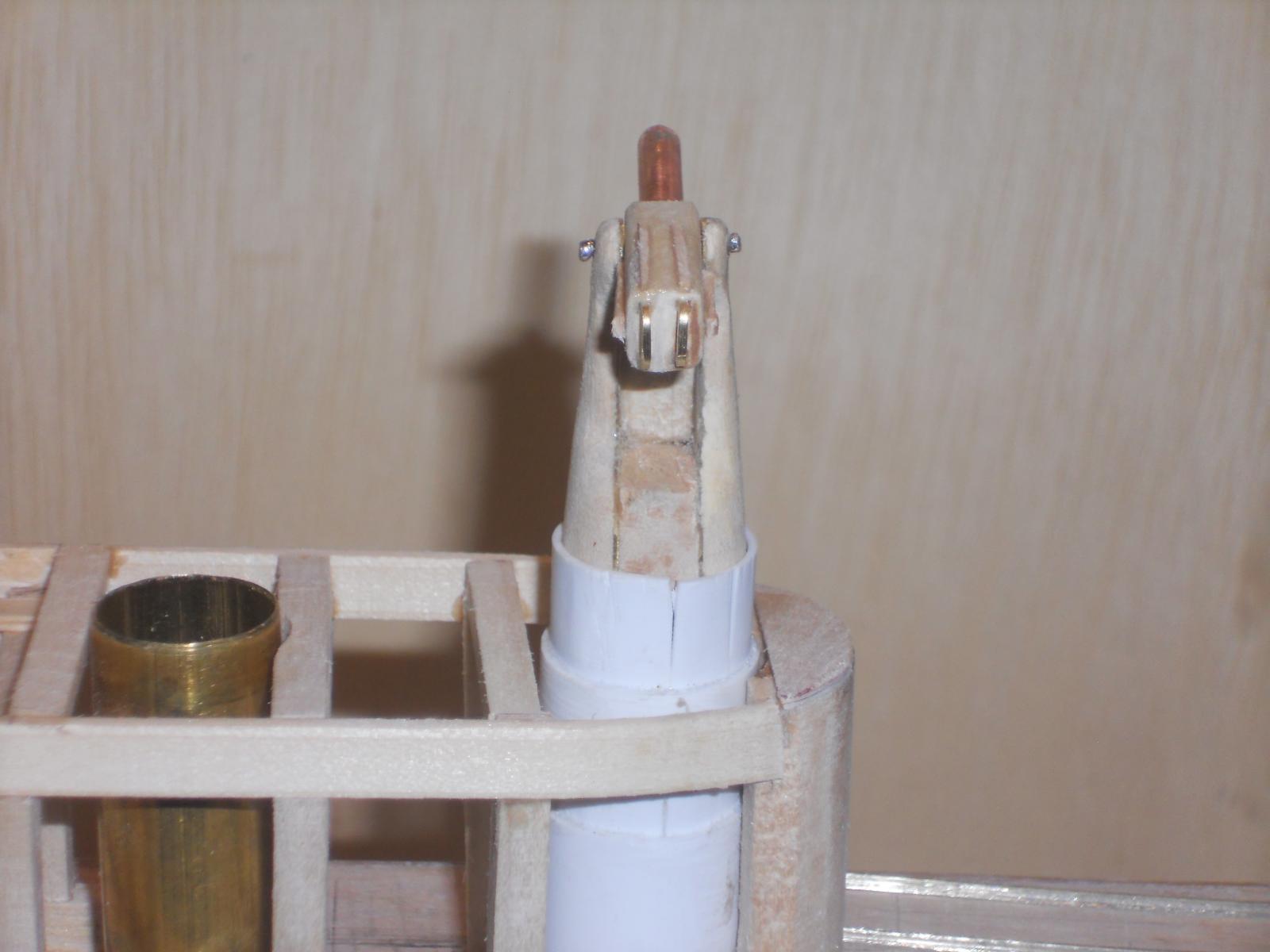
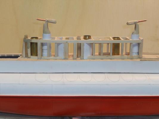
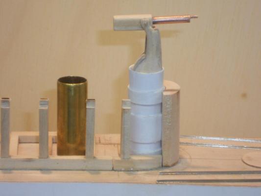
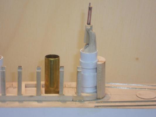
My sincere thanks to everyone who have visited my shipyard and clicked "like." It's much appreciated. Our best wishes for the holidays to everyone on MSW and may 2014 be prosperous, safe and with good health. @ John, thanks for the best wishes and Gwen and I extend our best wishes to you and Diane. We also cherish your visit and getting to know both of yuns. We'll try to keep up the good works and you do the same, your ship is really looking great, bravo. Today I could spend some quality time in the shipyard and worked some more on the AA guns. I added some detail and moved the barrels to the center of the cooling jacket. I don't know how much more I can add to these little buggers and need to start dressing them up some, removing the rough edges so to to speak. I'm ready to cement them to the piston and platform that'll go into the buns. So far they seem to work okay but I'm sure I'll need to do some fine-tuning. After these pesky guns are completed and in the buns I can start putting the side panels on the lower conning tower and the decks. Okay, here are a few pics of today's work. This is the forward 40 mm Vickers AA gun loosely stuck in the bun. You can see the double handgrip and some other stuff on the gun I tried to emulate from the photos. Same gun but now a frontal view to show Boris that the barrel is in the center I don't know about the gun-sight though. [ Same gun as seen from the back. You can see the double handgrips here. Starboard side view of the lower conning tower with both AA guns still loosely stuck in the buns. Here is a ¾ starboard side view looking aft of the lower con Cheers,

-
Hoi Freek, That's beginning to look really impressive. Now, if you had upped the scale by a factor of 3 you could have installed a real torpedo tube system that fires real torpedoes and with an explosive charge I'm kidding of course, no need to make everything workable. It's already a great job you did with the K XVIII!!! Cheers,
-
Lovely work on the wheels Dave! Marvelous idea, a prairie schooner - - - in a bottle no less. I've been following alright and "like" your progress. Cheers,
- 170 replies
-
- 1
-

-
- ogallala
- praire schooner
- (and 2 more)
-
Again, thanks to everyone who visited and clicked "like." It's much appreciated. @ Boris, no problem my friend, I already noticed it a few days ago and the barrel will go into the center when I have done the next one. This was just a prototype @ John, thanks for liking my efforts. Today was cut a little short. I had to visit my dentist in the morning to check how the implants in the left upper jaw look. He is very satisfied and next week i'll get the embutments installed, then the gums need to heal again, then the mold making for the crowns. This will be the last of a long process to restore my dentures and jaw bones that got hit through malnutrition during my time as the guest of the emperor of Japan, i.e. POW. Okay, yuns don't want to hear about that, sooooooh - - - here's what we did the rest of the day. I did some prelim shaping of the number two AA gun mount but could not resist working on the lower con. When I quit at 1700 hrs the cross beams were installed and the port side upper stringer is in clamps, curing the glue. I think that before I glue on the side panels of the lower con I should really finish the AA guns to make sure everything fits and works as advertised. I like to have access to the insides, just to make sure. I'm glad that Boris found only one fault with the guns but I already had plans to move the barrels to center. Somebody has to keep me straight The guns still need some more detail work too. No pics yet, this is just an update. Cheers,
-
To all who have visited my shipyard, thanks for your like votes, it's much appreciated. @ Freek, so, what's wrong with your gun, looks pretty good to me @ Ian, yes, that's a serious piece of armament alright. Thanks for the URL, impressive. I have also wondered about the same thing, did those guns not corrode and freeze up? But I guess subs being on the surface most of the time the crew would keep them well lubed and smeared in with a rust prohibiter. They may even fire a round or two to clean the barrel. Well, today I started on gun number 2. Tomorrow I'll start shaping it to make it look acceptable. Then I'll have add some of the details to it, nothing fancy, just enough. I have also continued working on the lower conning tower. All the frames are up and the top "longeron" on the starboard side is glued on. It's now ready to be faired. Tomorrow I'll do the port side and then the cross beams. Pretty soon I can put the sides on and start making the three doors on the port side. There is still a lot of detail stuff for this portion of the build. Well, this is it for today, sorry no pics, just a lot of detail work
-
Hey Popeye, thank you too for dropping in and your very kind words. I just hope that Boris and Gino like it. I'm waiting for the second one till I get the green light Keep our fingers crossed. Cheers,
-
Hi Mark, Thanks for looking in and your eval. I didn't knew either, remember, I'm an airplane guy True, not all subs retracted their AA guns into watertight compartments. Later on during the war the Dutch subs were refitted in Scotland and they left them out. What I also didn't know was that the Polish submarine "Orzel" had her deck gun also inside a watertight compartment. This allowed the crew to already man the gun when surfacing. That boat was also build in the Netherlands and my father visited her build as well. He was rather impressed with her. The commander of the Orzel understood that my father was the quality control officer for the O19 and asked him to look his boat over. The result was a list of "squawks' they handed over to the boatbuilder. Yes, my dad was a trouble maker alright The US subs don't retract their guns, at least as far as I know and they had the 40 mm Bofors.
-
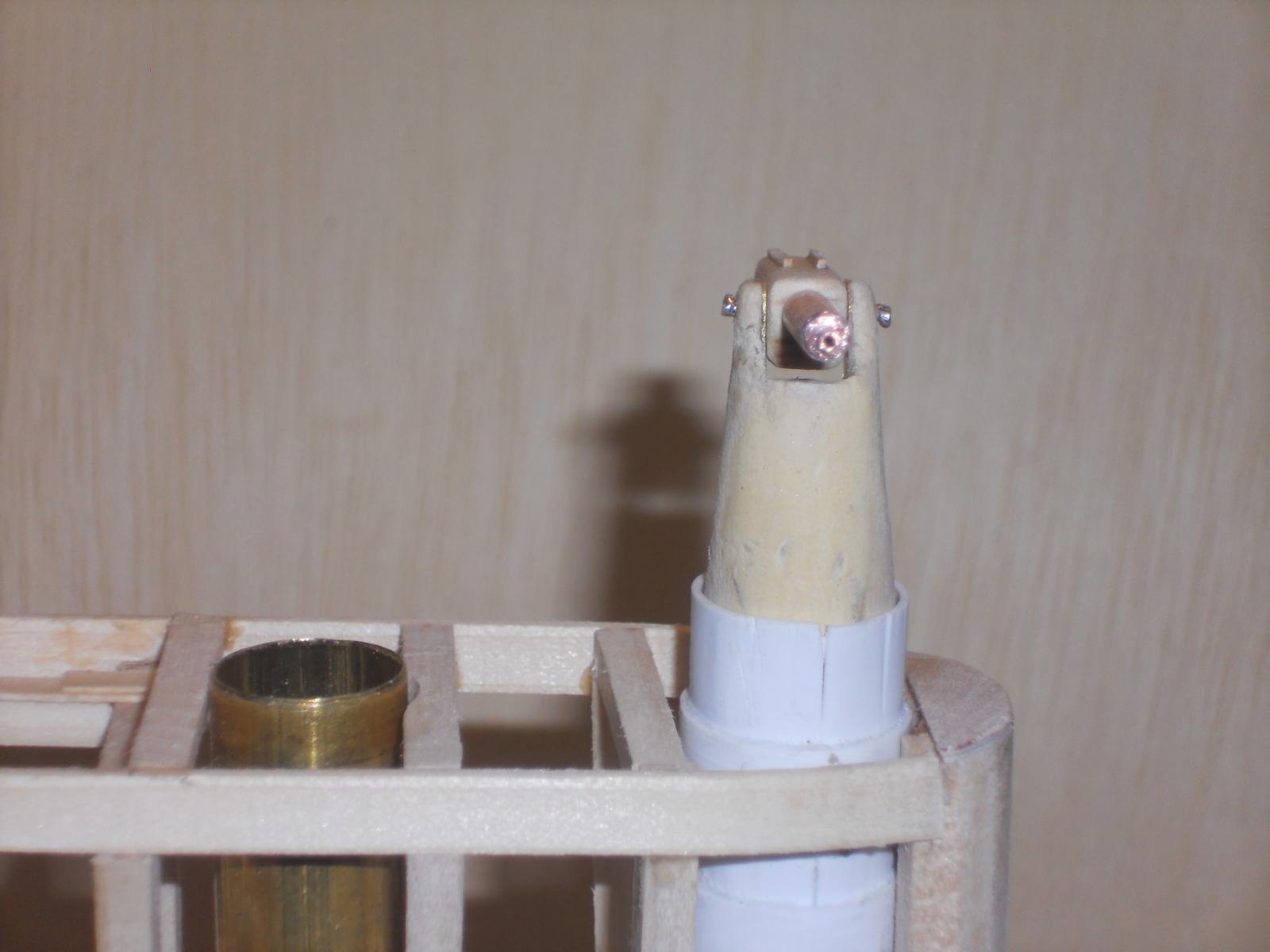
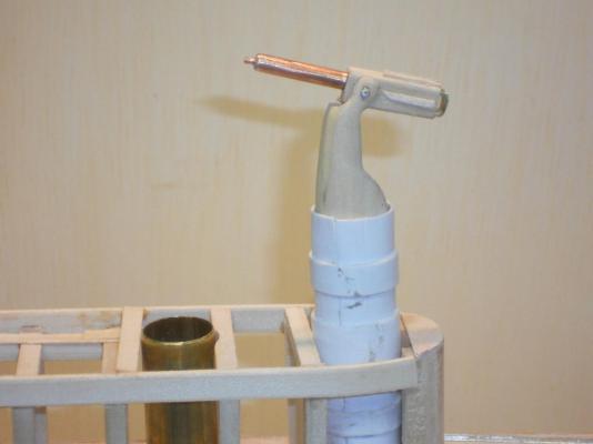
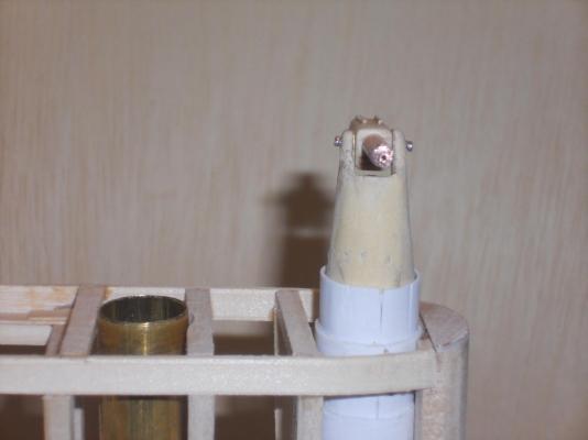
Thanks everyone for visiting. @ John (Lad), yes, so am I As explained above, with conflicting data it was not easy to sift through all that and come to a viable solution. @ Popeye, thanks for the pat on the back and your confidence. @ Greg, thank you as well for your kind words. Today was rather cool in the shipyard, aka the garage, it was only 60 F. I had to wear a heavy long-sleaved shirt AND a jacket! Brrrrrr However, I "suffered" through it and worked on the AA gun mount as a prototype. I also made the gun and installed it to the pedestal/mount. I think it kinda looks similar to the pics Boris send and the ones I copied from the Internet. At this scale it's not easy to also make the gun itself pivot in the mount. I gave it a dry-run before taking a few pics and it works nice and smooth. The gun swivels stiff enough to hold its position, which is also a winner. Eventually the guns will also be painted in the same light grey as everything else above the deck sheer. If this prototype is acceptable then I'll finish it up and make the second one for the aft position. I also continued with the rest of the lower con framing and hope to have that cemented in place sometime this week. This is prototype 1 of the Vickers 40 mm Pom Pom ready for action. The white portion of the styrene bun is what sticks out above the gun deck. It will have a brass ring around it and have the hinges for the watertight lid. I can only do that after the deck is installed. The styrene will not be visible. This is prototype 1 of the Vickers 40 mm Pom Pom made ready to be retracted into its bun. This is prototype 1 of the Vickers 40 mm Pom Pom retracted into its bun. Cheers,

-
Thanks everyone for visiting and your support. Today I cemented the two guide tubes for the AA gun platform piston. They are way down into the pressure hull part and the central vertical false keel. It guides the platform piston very nicely. Now I'm ready to make the gun pedestals and the guns themselves. I started with prototype one and see how it turns out. If it works and looks like the pics Boris shared with me and others I found then we'll make the second one. I didn't make a photo of this prototype yet, I need to see first how it looks all dressed up. I also continued with the lower con framing and cemented the forward starboard framing wall. The port side is ready to be cemented to the deck but that'll be done tomorrow. Well, that's about it for today. The framing section is just aft of the forward AA gun tube, that styrene thingy on the right. All the tubes are still loose and I may leave them that way till the deck pieces are ready to be cemented on. Cheers,
-
Thank you Boris for bringing this to our attention. This may be a thread for another part of MSW to properly comment on because it will involve politics, which is not part of this "scratch build" models. Moderator input please. Cheers,
-
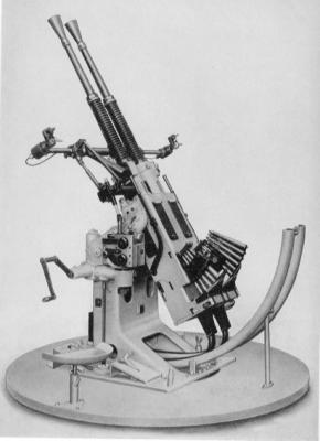
Hello everyone, never fear, Piet is here I had a very interesting exchange of thoughts with Gino den Ridder. Yes, we agree, there is still some confusion between several reports. Some say 40 mm Bofors others say 40 mm Vickers. However, Gino mentions that the Dutch Navy has been using the vickers guns for many years and would most likely not have switched to Bofors so close to the outbreak of hostilities in Europe. Gino mentioned that the Vickers guns for the O19 and O20 were the L/39 2 pounder, which is a derivative from the 37 mm 1 pounder gun. Okay, I also went searching and read-up on the Vickers guns on the Internet as well as the Dutch sites, one being www.dutchfleet.net. I have been a member for many years but rarely visit after not finding answers to my questions about my father. Sooooh, bottom line is that I'll be modeling the Vickers 40 mm 2 pounder "Pom - Pom," on the navy base. I have already downloaded a few pics to use as examples to model from (thanks Boris). Oh, I have not been idle with the build and continued with the AA gun installation "stuff." Most everything for that project is ready to permanently cemented in and work on the guns themselves. I also need to finish the mount itself to make it look like the ones on the photos. All in all this has been a very interesting and educational exercise and learned that the Vickers 37 mm and 40 mm "Pom - Pom" guns were not rated as effective as the Bofors guns. There is a small single barrel 40 mm Bofors that could be made to fit on the Vickers mount, this and the mentioning of the 40 mm Bofors on the spec sheet I downloaded from the Dutch website www.dutchsubmarines.com, made me automatically assume that these boats had Bofors and went with it. @ Daniel, a doctoral thesis? This is nothing compared to some other people's builds, fortunately The intend is to build this model as close as possible to the real boat as she was when commissioned in 1939 when my father sailed with her back to the Netherlands east Indies. He was also a stickler for details and accuracy. The issue with the AA guns is as important to me as others have in building a model of any other historic ship, they should come as close as possible to be true. Look at what Nenad goes through with his Cutty Sark and so many other modelers, doing painstaking research on details. Updates are coming soon my friend, my fingers are itching to complete these little pesky guns @ John, no John, no disappointments. We just had to spend some time to get the facts straight as best as the available data allows it. Now that we have made up our minds it's full speed ahead Cheers,
-
Have a great vacation and holidays, we'll be here waiting. Cheers,
-
Hello Boris and Freek, thanks again for the input and pics. This is rather interesting but we have a controversy here. According to the website "dutchfleet.net" the O19 and 020 were equipped with 40 mm Vickers guns but why would the original spec sheet call out the 40 mm Bofors????? Were they installed when they were build in 1938 or not???? Who is right???? That the O19 received the Vickers guns in 1943 is well documented and mentioned on the spec sheet, but again, which guns were originally installed on the O19???? I have absolutely no problem in trying to model a Vickers gun, it's not that much work. It's now getting a little late in the evening but tomorrow I'll send an e-mail to both links and ask the question. I don't know if Gino den Ridder knows for sure but I'll send him an e-mail as well. In the meantime I'm progressing with the AA gun tubes and the gun lifts. I have started to make the gun mount/pedestal which can be adapted to either gun. I have also made the two guns, more or less modeled after the Bofors. This too is not much of a problem to remake them to look like the Vickers, if need be. I can lift the entire gun off it's platform anyhow, they will be able to rotate via a pin in a tube. In the meantime this project is on hold till I am relatively sure. Thank you both for your help, we'll solve the riddle soon, I hope Cheers,
-
Hello Boris and Freek, thank you both for your responses and help, it's much appreciated. First of all, remember that my model of the O19 reflects the time period that my father was on board as a member of the crew, which was between 1938 and january 1941. According to the original specification sheets of 1938 the O19 and O20 had quote "2 x 40 mm Bofors in single 'disappearing' mounts, in watertight wells forward and aft of the conning tower" unquote. I have posted this spec sheet when I started this build and is on post #9. I venture to guess that the subs build after the O19 and O20 also had the same Bofors. It would have been more economical to purchase a bunch at the same time. What the K XVIII had or others before it, is a guess and really not relevant to my search. The K XVIII could very well also have had the same Bofors. Also, according to the list of guns manufactured by Bofors and those in the States under license lists only one 40 mm AA gun, the type L/43, for submarines, mounted on disappearing mounts. The drawings I have of the O19 do not show these guns having such a large round chamber just aft of the barrel. It looks more like what I see Bofors look like. Remember that the Bofors are not just machine guns but something more substantial. I know that the Dutch subs all head to go to Scotland to be refurbished and had their armaments changed to those that could fit british arms. Reason being, the Dutch submarine supply ship was sunk by Jap action and all spare parts and ammo was lost. The O19 had the forward AA gun deck removed and the aft Bofors was replaced with the Oerlikon machine gun. Boris is correct in that. But again, we are not dealing with a model build after 1941, we are prior to the war with Japan. I have to stick with the Bofors gun and looking at the spec sheet they may be a single barrel gun that looks like the last pic Boris posted. Boris can translate what is described on one of the drawing picture, that would be interesting to me and helpful A single barrel gun makes sense to me, however the two barrel gun will also fit in the tube if we remove the gun-sights. I think the single barrel Bofors is what I should concentrate on. Some more research my be in order but honestly, I would be hard pressed to make these guns look like the originals Thank you Freek for the outstanding photos of the deck gun. That'll help me a lot in modeling my deck gun. You guys are great, thanks for the input and help. Cheers,
-
Hey Rob, what do you mean "your painting looks awful." These figure heads were not made by Michael Angelo you know I think it looks terrific and watch out for that "old" word, not a good word to use when other "old" people are around - - - me In any case, I like it and like your build. Cheers,
-
Wow, John, looks like real in miniature. Am awaiting your experiments with the ageing washes, that'll really make it. Cheers,
- 2,250 replies
-
- 1
-
-
- model shipways
- Charles W Morgan
- (and 1 more)
-
Wow, I am humbled by the many who have visited and like my build, thanks every one. @ Kevin, hello, I missed your visits, glad to see you again. Yes, I understand you are busy. Thanks for your kind words and yes, I figured that not many people know much about how these older subs were build and equipped. That way I am also learning, - - - with me having spend my entire adult live with airplanes, subs were not upper most in my mind. @ Popeye, thanks my friend! @ Sailor, Yes, I know you have served in Royal Canadian Submarine service, thank you for your service sir. Thank you also for your kind words, I really appreciate it coming from "bubble heads" you and Kevin @ John, thank you, thank you. Actually, I should get my head examined to add so much detail but hey, what else can I do in my "free" time. Don't ask the Admiral, she'll give you a list your arm long @ Boris, my Russian friend, thanks for searching on the internet for "pop poms." Those look like water cooled guns and unfortunately they were not used on the subs However, they look really spiffy. Hmmmm, spiffy, now translate that one into Russian Thank you all for checking in and your encouraging words and help. I did some snooping on Google last night and came up with a Bofors 40 mm gun that was designed for subs in the mid thirties. It looks like the gun that was used on the O 19 and subsequent builds, at least according to the specs. It's a type L/43 that fits into a watertight tube and just what the doctor ordered. See pic below. I also found a complete assembly manual for that gun, so now I can also put one together if i had all the parts I checking for the space I need to make the gun fit inside the tube and found that I needed a deeper hole into the central keel, which is at this stage of the game a rather touchy proposition. But I managed to do so without hardly any damage. Now I can go ahead and finish that project. It'll take some time, though. At least I have a few good examples to work with. My third try with the styrene tubes look really good. I am now cementing the outside reinforcing rings on and continue with making frames. This is the gun designed by Bofors for submarines around 1935 or so, the L/43 type. I think you all agree it looks like the real McCoy. I hope I won't disappoint John Texxn5 Cheers,
-
Hello Boris, That looks terrific my friend. I like the detail on the decking. I dread doing mine, even at a larger scale then yours. Cheers,
-
That looks very nice Popeye, love the ladder! Could you have made the gunport ropes from a darker thread? Dark tan perhaps? Just a thought Cheers,