Piet
-
Posts
3,568 -
Joined
-
Last visited
Content Type
Profiles
Forums
Gallery
Events
Everything posted by Piet
-
 Hello Bob, Looking real spiffy and real like! Great job. Now back to building the rest of her Cheers
 -
Sherry, I too want to extend my sincere condolences for your loss. May the Almighty One give you and your family strength. In Christian love,
-
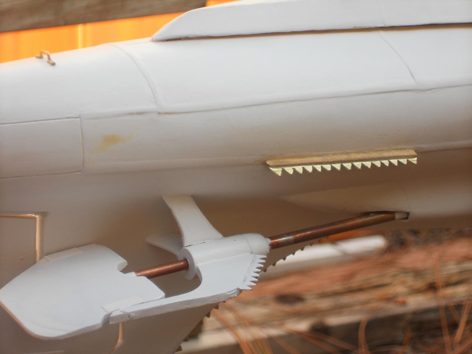
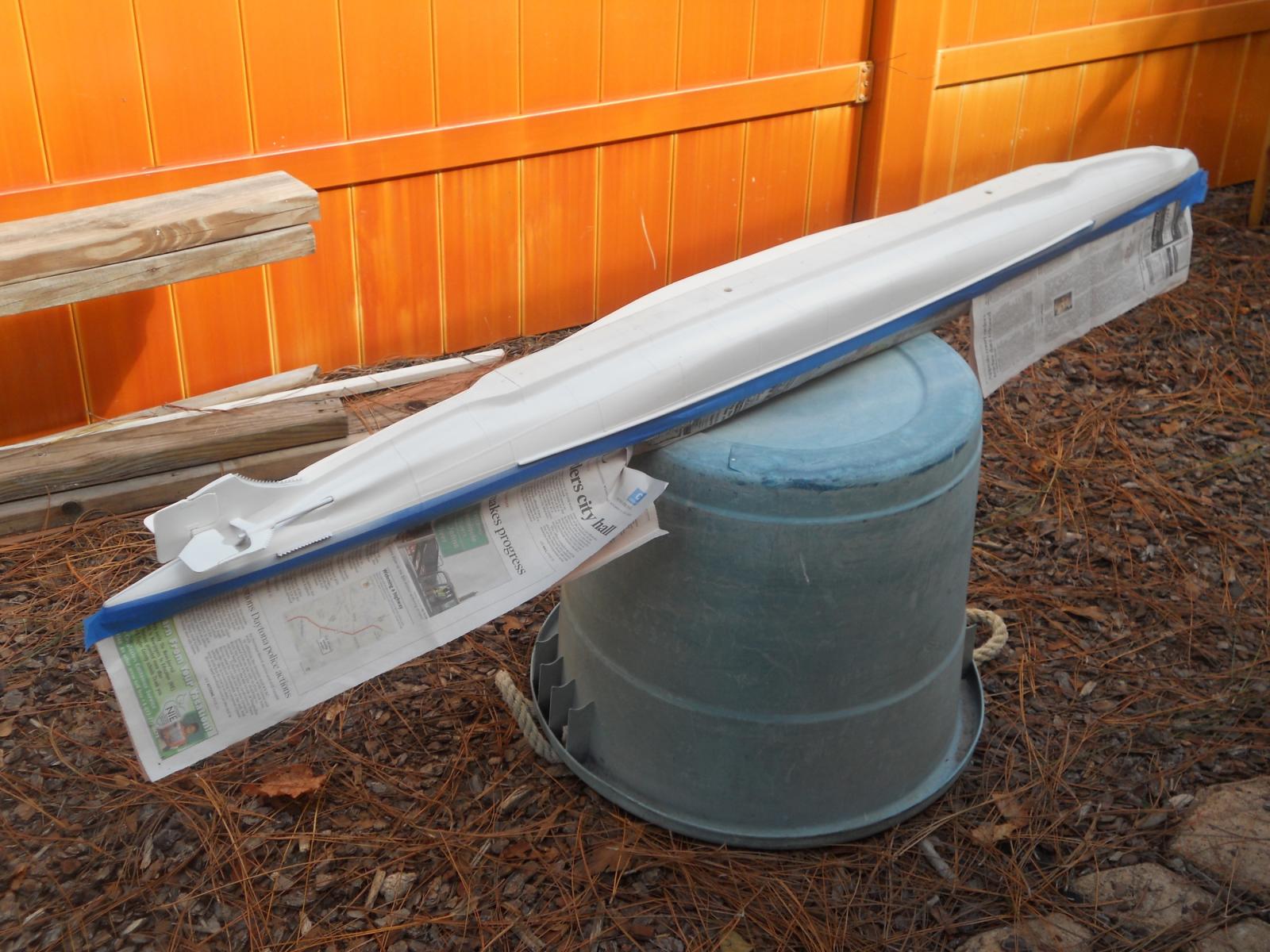
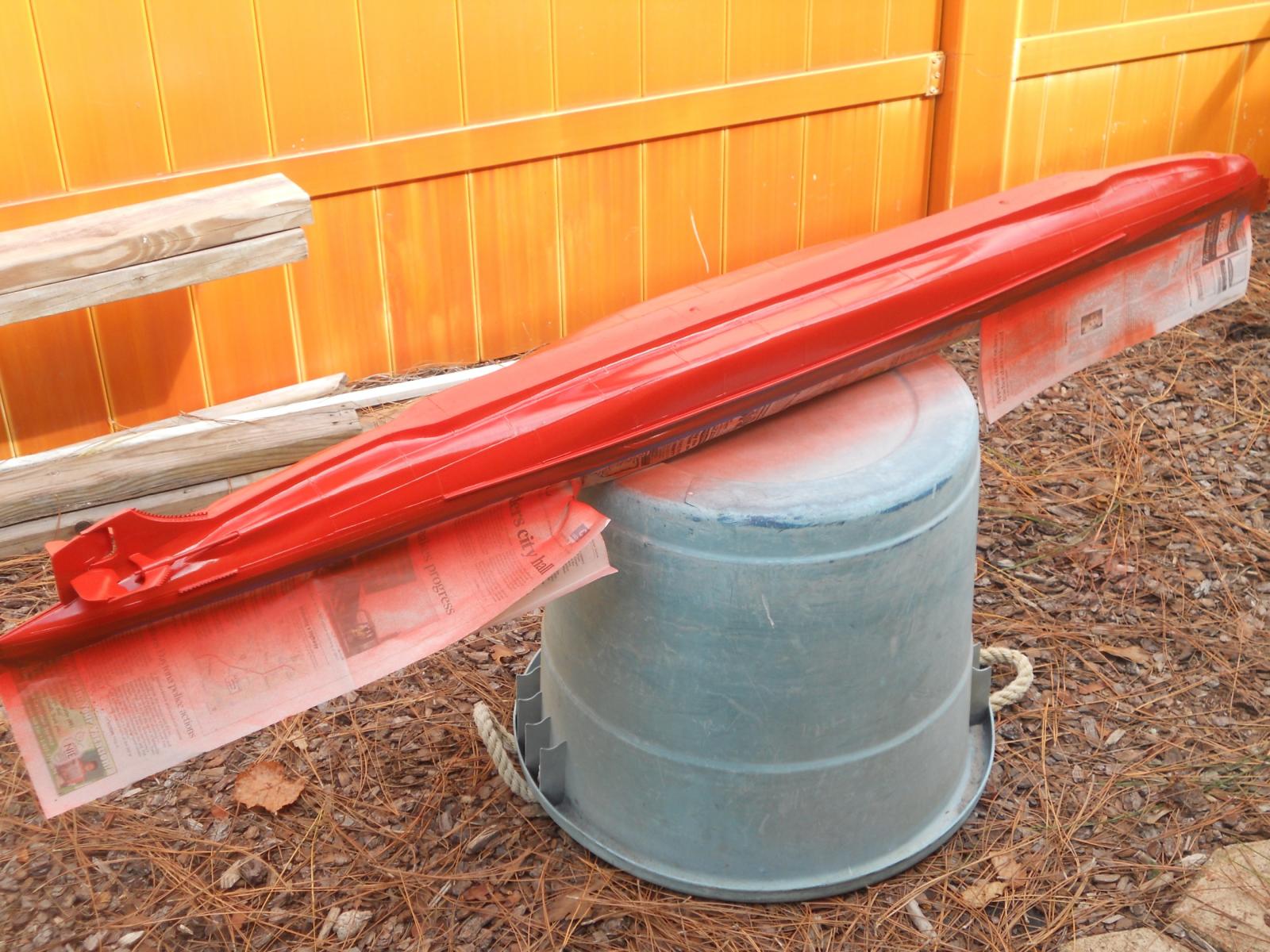
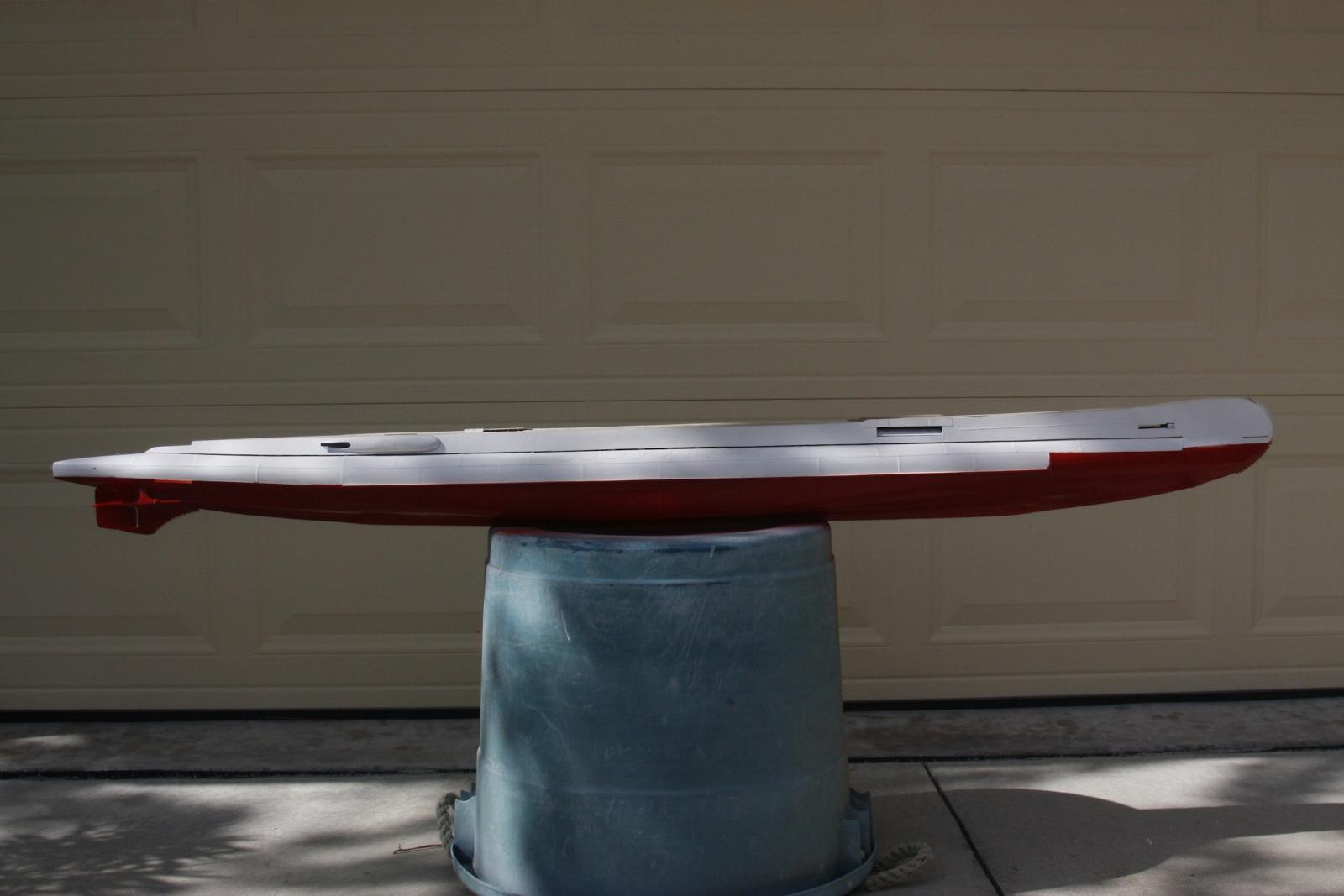
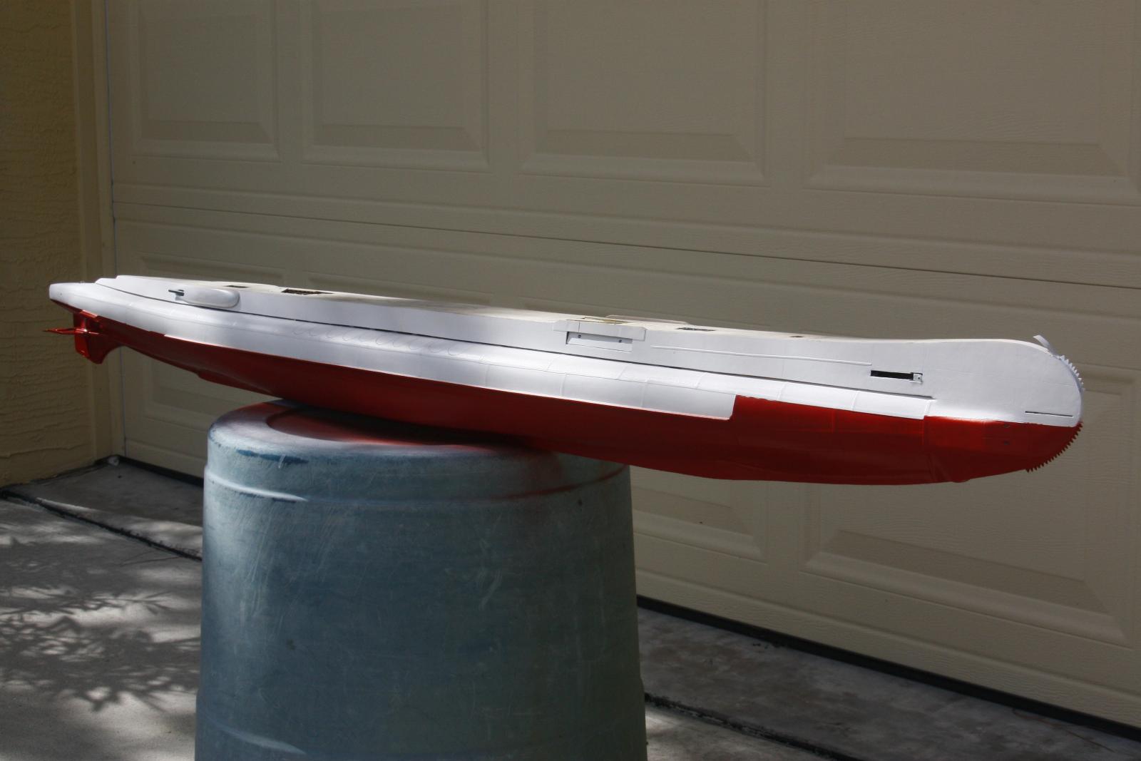
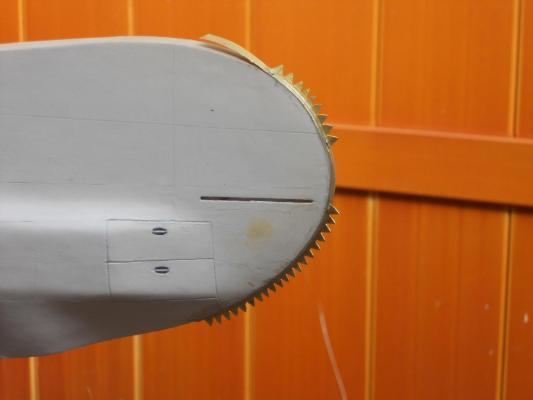
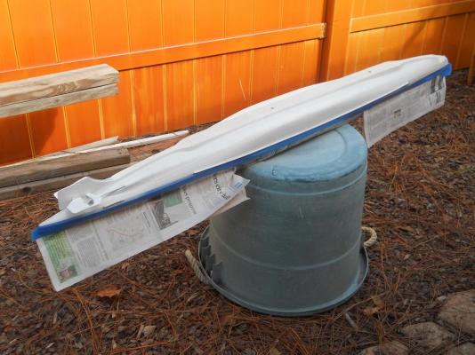
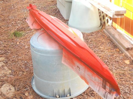
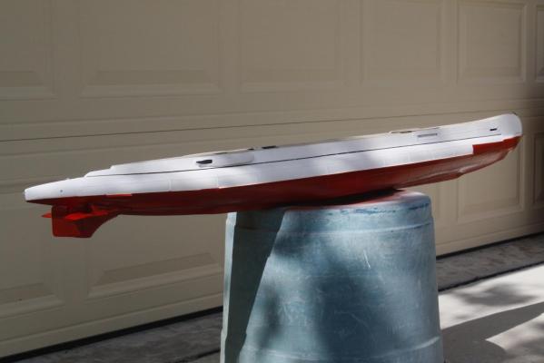
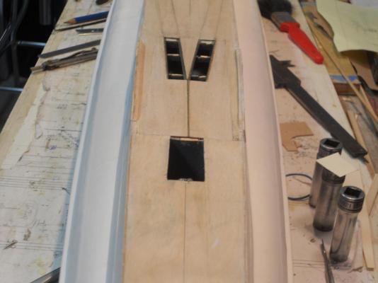
Thank you all for dropping in, enjoy the fresh popcorn and some good belgian ale. @ John (texxn5), hmmmm, yes John I have X-ray eyes that bounce off of the satilite and see you smirk'n Well, today I dressed up the net - cable cutters I cemented on yesterday and prepped the boat ready for painting the bottom. I took her outside to paint, weather was nice and warm, some sunshine and very little wind. I masked the the hull above waterline 7, that's the one with the dock bumper or wale. This was mainly done to keep the overspray off of the white primer. The paint I was originally going to use was just the wrong red so I bought a "rattle can" of RustOleum Satin Paprika. I is not quite the same as the color photo of the model but it's close enough. The reason for a red bottom is that below water it appears more like a very dark brown. At night all red colors appear black. After I removed the masking paper I let the boat sit outside to let the paint dry and went inside for lunch. After lunch I made a few pics for the profile thingy and took the boat back into the garage and put it on the build board. I shouldn't have to remove for some time now and can proceed with the stuff on and above the deck. I cut two round holes in the deck structure for the escape hatches and cut two 17 mm brass tubes for the hatch tubes. One more to go just aft of the deck launcher and between the tracks. Talking about tracks, I completed grinding the flanges away from the four pieces of N gauge tracks that will be cemented forward of the con. There are still some long ones to tackle that going aft. I also made six of the torpedo loading access hatch doors above the deck launcher. There will be three on each side. The rest going aft will be simulated between the rails like the rest of other hatch doors except those at the dingy "hangar." Well, that was a productive day and am pleased how she is turning out. Can't wait for the con to go on but must exercise patience Okay, here are the pics of today's work. This is a close-up of the bow net /cable cutter. There will be a "steel rod" structure at the bow for the antenna support and there will also be an extension of the net /cable cutter on top of the center steel tube. There is still a lot of small detail work to do. This shows the small horizontal net / cable cutters on the side of the hull. This pic shows the masking for the overspray. A shot of the now freshly painted bottom of the gull. Another shot of the freshly painted bottom. At the bow and stern I painted it a little higher then the intended demarkation line of the red bottom and the green top. Reason is that I can now feather the small sections to prevent a masking line under the green. The demarkation line will be at waterline 7, which is at the dock bumper or wale. That line will be level with the waterline from stem to stern. Thus some of the red you see here will disappear under the green. You can also see the mushroom anchor at the keel close to the bow. I placed the painted hull in front of the garage door for some nice shots of the hull Here you see the six hatch doors between the tracks over the deck torpedo launcher. They are ready to get their hinges put on. Further to the bow you can see the forward exit hatch tube. This thing is just stuck into the hole, it still needs a ladder, hinges and the pressure door before I can permanently cement it in place. Cheers,


-
Hello all y'all ship builders and thanks for dropping in and your like votes! @ Popeye, wow, thanks for spending the time to scrounge up those URL's. I'll be looking into it and see what I can find that I can use. The O 19 numbers and letters is rather odd and I may have to avail on Remco to make them for me. He has a method to duplicate them exactly as they were. @ John (texxn5), and why do I see a sh-t eat'n grin on your face? Straight face indeed Just for yuns info - - - there is a plan being cooked up by them sawdust worms, miracles are not out of this world yet @ John (Lad), you know, I thrive on pressure, makes me think harder - - - - uh oh, what's that stuff coming out of my ears?? Oh - - - it's smoke! Brain is heating up Cheers,
-
Hi Nenad and I hope you'll feel better soon and lick this flu thing. We are anxiously looking forward to more pics of your work. Cheers,
-
Hmmmmm - - - - I'm waking up the woodworms in my skull to help me out, nothing else there but sawdust. No pressure - - - says he with a straight face too, and yes, all yuns LOVE to turn the screws on to this old - - - uh oh, there is that dreaded word again - - - befuddled ex Dutchman Well, as I said before, I am thinking about it - - - - - as he is pulling what little hair he has left from his head Cheers,
-
Looks like you got things well under control Adriaan, carry on Cheers,
-
Sky light - - - yippee! Just take your time with it Cheers,
- 2,250 replies
-
- 1
-

-
- model shipways
- Charles W Morgan
- (and 1 more)
-
Tanks for looking in Adriaan, Popeye, Sherry, Sjors, Daniel and Mark and for your like votes, much appreciated. @ John (Lad), thank you for agreeing with me Yes, fitting these small pieces of decking was time consuming, filing wood away one molecule at a time but in the end it paid off, I only had to remake one piece. @ John Texxn5), yup, it sure makes a big difference with the deck closed. Now I need to make the hatch doors that fit in between the rails. The anchor should not be a big problem. I have to wait for the copper to arrive from Paul out of Malta, provided there is enough left over from making the propeller blades. Well, yeah, the mine storage tube issue looks very simple but in reality it's really not. There has to be a part of the round pressure hull visible behind the tubes and on each side is a frame with on the topside a flange with lighting holes. All that has to be made and then try to worm it inside an empty space with nothing to adhere it to. How do you attach something to nothing? You have to make that something first and then see how to wriggle it inside that small opening. Magic?? But I'm thinking about it though. Yes indeed, I'm forging ahead with the needed work before the con and am still making sketches for it. @ Popeye, thanks my friend for your encouragement. Am very curious about your three-ship holiday project Today I did some metal work for a change. I made the small horizontal net / cable cutters at the stern, the ones just above the prop shaft bearing housing, and the bow net / cable cutter. They are just cemented on with epoxy and in "the raw" so to speak. No pics though because I want to first dress them up nice for all yuns to look at. I bend small strips of .3 mm brass sheet to 90 degrees to create a small edge to solder to a strip of .2mm brass sheet. This way I can bend them to the curve of the bow without the teeth part separating. I used a small cut-off disk to shape the teeth but had to finalize it with a knife edge file. They came out okay. A final touching up after the cement has cured. Did I hear "paint the bottom of the boat"? Hmmmm, my hearing is playing tricks on me, again That's what happens when you get old - - - - I mean - - - respectably ancient This is it then for this day and now back to my drafting table and work some more on the conning tower drawings. All y'all have a great rest of the day or new day, whichever case may be. Cheers,
-
Smart idea, better be safe then sorry. 3 X 7 is pretty stout and should work but - - - Any pre-bending to relieve the strain at the bow? Cheers,
-
Hello Sherry, just stupendous looking work !!!! What a joy it is to watch such a magnificent ship taking shape with such craftsmanship Hope your brother is recovering. Cheers,
-
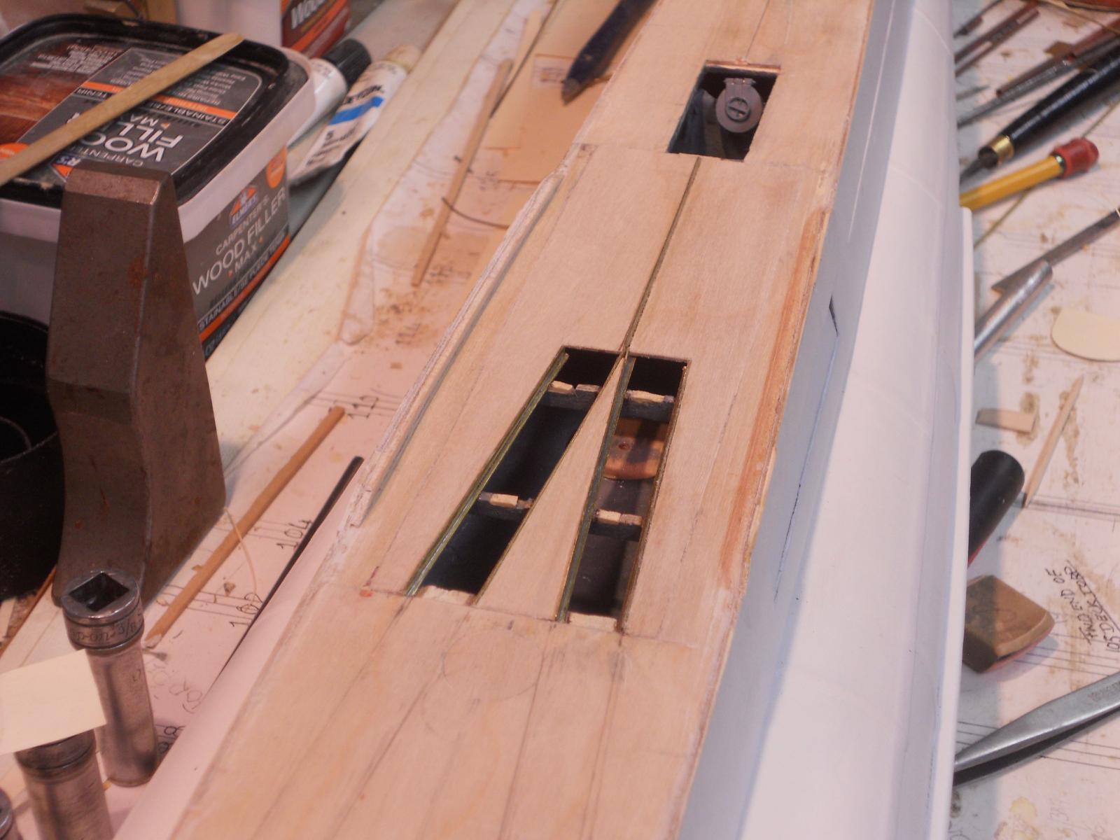
Hello every one and thanks to Mark, Daniel, Sjors, Nenad and Freek for dropping in, much appreciate the encouragement. @ Freek, You know, I just overlooked that anchor on the floor of the dock, even with that cable running down. Hmmm - - - what kind of excuses can I dream up - - - Not many, just not paying attention And yes, that looks like a Hall type anchor all right. Should be an interesting project making one. Well, today the Admiral wanted me to cut down a bush or two in the backyard so very little time in the shipyard. I did manage to cut the decking pieces between the rails over the deck torp launcher and cement them in. Then I dry-fit the N-gauge rail tracks to see how they look but now I have to grind off the sides of the top of the rails. It measured to .8 mm and at my scale of 1:50 that works out to 40 mm wide. Much to wide for the original rails. After grinding away the excess it measured to .2 mm which is closer to scale. I can't get it any thinner and besides, it is the same thickness as the brass rails I made for over the deck torp launcher. It's just a lot of work to that to do all the rails though but so what - - - I also started on making the two small net / cable cutters at the stern end just forward and above the propeller bearing housing. The mailman also delivered the 21/32 inch brass tubing for the crew escape hatches Now I can also cut them to size and make the ladders for them. I think though that I'll make the bow net / cable cutters and install them first. I need to lift the model out of it's build dock to fasten them to the bottom part and need to have the deck clear of any obstructions. Let me show the work I did this afternoon, I'm quite happy with it This is looking forward and shows the rails and associated decking installed. Remember that I cut that part of the deck out some time ago and only made two rails for one row of hatch doors. This was not in accordance with the drawings and photos of the real boat. So I had to redo all that. I tried to make the deck pieces fit as tight as I could manage and even the photos show very little edge seams, I am happy with it. There is no putty used! The "teak" deck slats will cover most of whatever seam is visible and then painted. That steel hunk to the left in the pic is a bucking bar (I used in a previous life repairing aircraft) to hold the deck pieces down, the same with the socket wrenches with a steel bar on top. As it turned out it didn't hold the pieces down tight enough so I mixed some 1 minute epoxy and held it down by hand. Yeah, it says it's 5 minute epoxy but even when I mix less hardener in it it still cures rather fast. I don't mind it but I can only work with one or two things at a time. This is the same work but now looking aft. Cheers,

-
Marvelous, simply marvelous! Will there be more filler wood in the bow to support the planking there? Cheers,
-
Hey John, it's in the low 80s here and I'm having breakfast outside next to the pond btw your stern end of the ship looks fab! even with that blue - green lozenge as a life preserver kidding! Keep up the good works my friend. Cheers,
- 2,250 replies
-
- 2
-
-
- model shipways
- Charles W Morgan
- (and 1 more)
-
I'm sorry to hear all that and wish you and the Admiral good luck. I understand your predicament, been there. Wonder what's wrong with people - - - hmm, maybe not. Cheers,
-
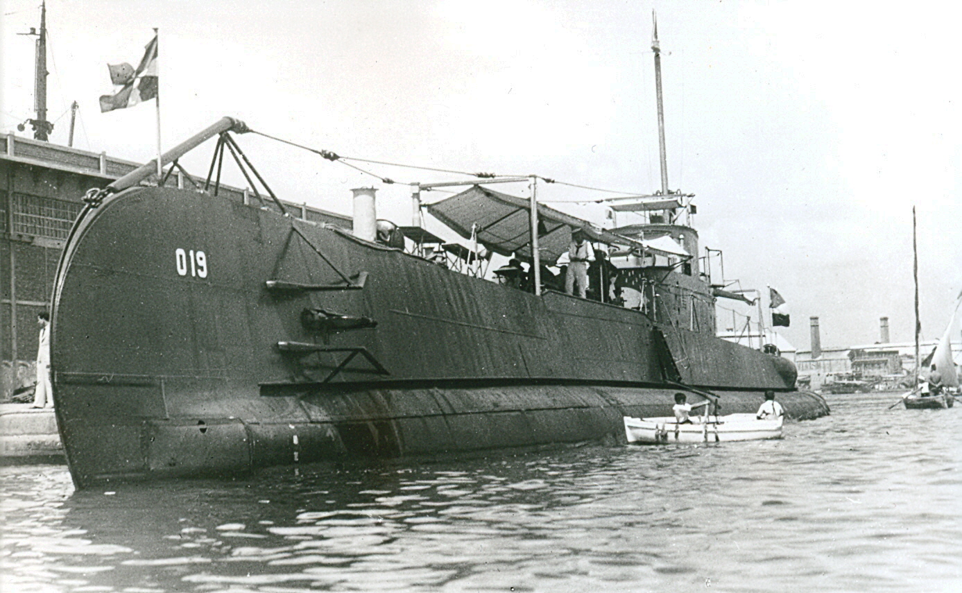
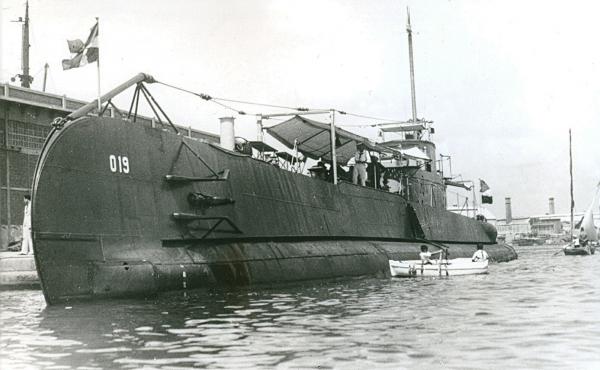
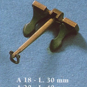
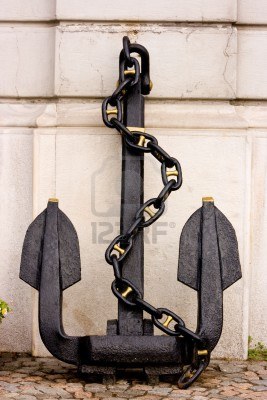
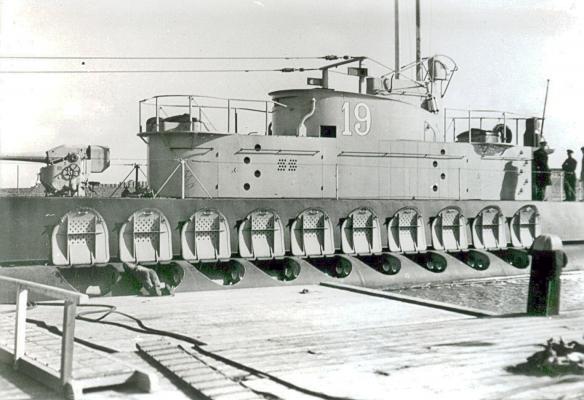
Greetings to Freek, Ian, Daniel, mark and Elia, thanks for dropping in. @ John (Lad), Yes, that is also my thinking. It certainly looks like a small Hall type anchor and most likely an auxiliary anchor relying on the mushroom anchor that drops down from the bottom of the keel. @ Daniel, That's a great idea making a collage of these pics. I want to make a nice folder or binder to put most of the photos I have with the plans and a historical narrative on the O 19 and place it with the finished model. The purpose of the "teeth" at the bow and stern parts are to function as net and cable cutters. They are supposed to enable the sub to cut through security nets of enemy harbors that are suppose to prevent subs or surface ships from entering. @ Freek, Thanks for photo of the K XVIII in it's build dock. It clearly shows the place where the anchor is stowed. I don't think that the K XVIII had a keel drop-down anchor as the O 19 and O 20 had. It also looks a little larger and is at the starboard side The picture in my previous post with the O 19 surfacing, and a few others I have, it appears that the O 19 and O 20 had some extra metal in front of the anchor opening as fairings. I now vaguely remember having seen a photo of an earlier sub where the bottom of the anchor is clearly visible on the side. I guess I could go back to the picture archive of the KM and search for it. However, at this point I'm pretty well convinced in how to shape my anchor. Not much activity in the shipyard, I had to run a few errands. I was also hunting for a few previously marked angle pieces for the bow net / chain cutter. I Put them with other "to do" things but they got moved underneath some of them and overlooked them. I did cement the rails on the beams above the deck launched torpedo tubes. I got sick and tired at looking at that open hole in the deck And it emptied the "to do" shelf some so I won't loose them again Now I can also add the missing decking and make the hatch doors between the tracks. I just don't want to think about all the hinge pieces I still have to make I also did some "Googling" to find model anchors. The one in the top of the pics of yesterday's post I found at a place in the UK, "cornwallmodelboats. com. I think it's probably the best illustration to model my anchor on. Should not be too difficult. So, now I have pictures and drawings for the anchor and the propellers, great - - - what else do I need - - - plenty! The deck gun and the two AA guns to start with. I do have a few nice photos of the deck gun so that should not be a big problem to model. Next I have to find some good pics of the AA guns. Then back to sketching the draft working drawings for the con. It's all a slow process. Here is a nice photo of the O 19 dockside in Alexandria, Egypt. As you all can see she did not yet have her teeth yet, these were added later on. This was sometime June 1939 when my father sailed on her when she was on the way to the NOI (Netherlands East Indies). Oh, I still remember the stories my father told us about that voyage. One was how they caught a shark in the Indian Ocean and he brought a few teeth with him to show us, and they were sharp! How do I know? I cut myself, that's how and my father was laughing. This one is for your collage Ian, hope you like it. Cheers,
-
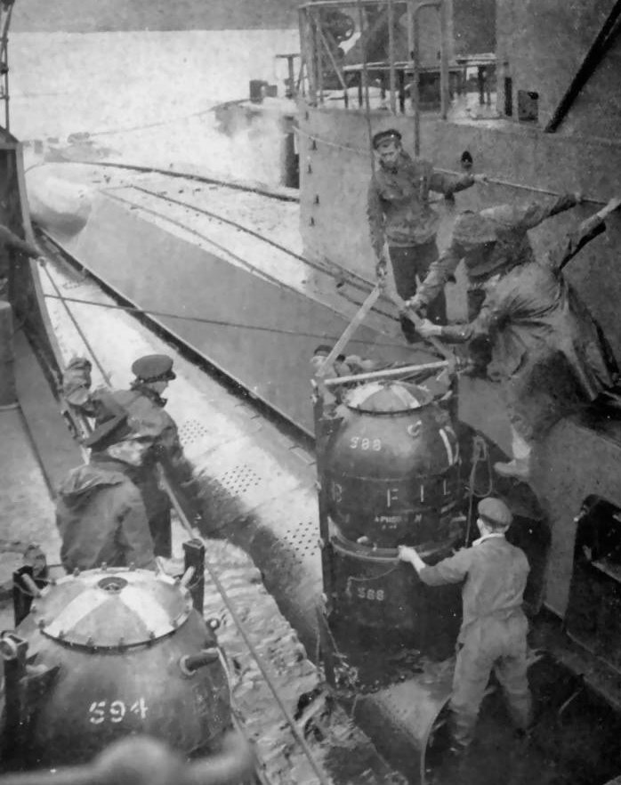
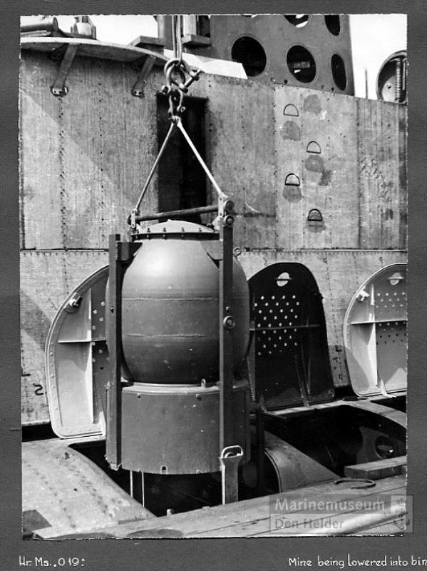
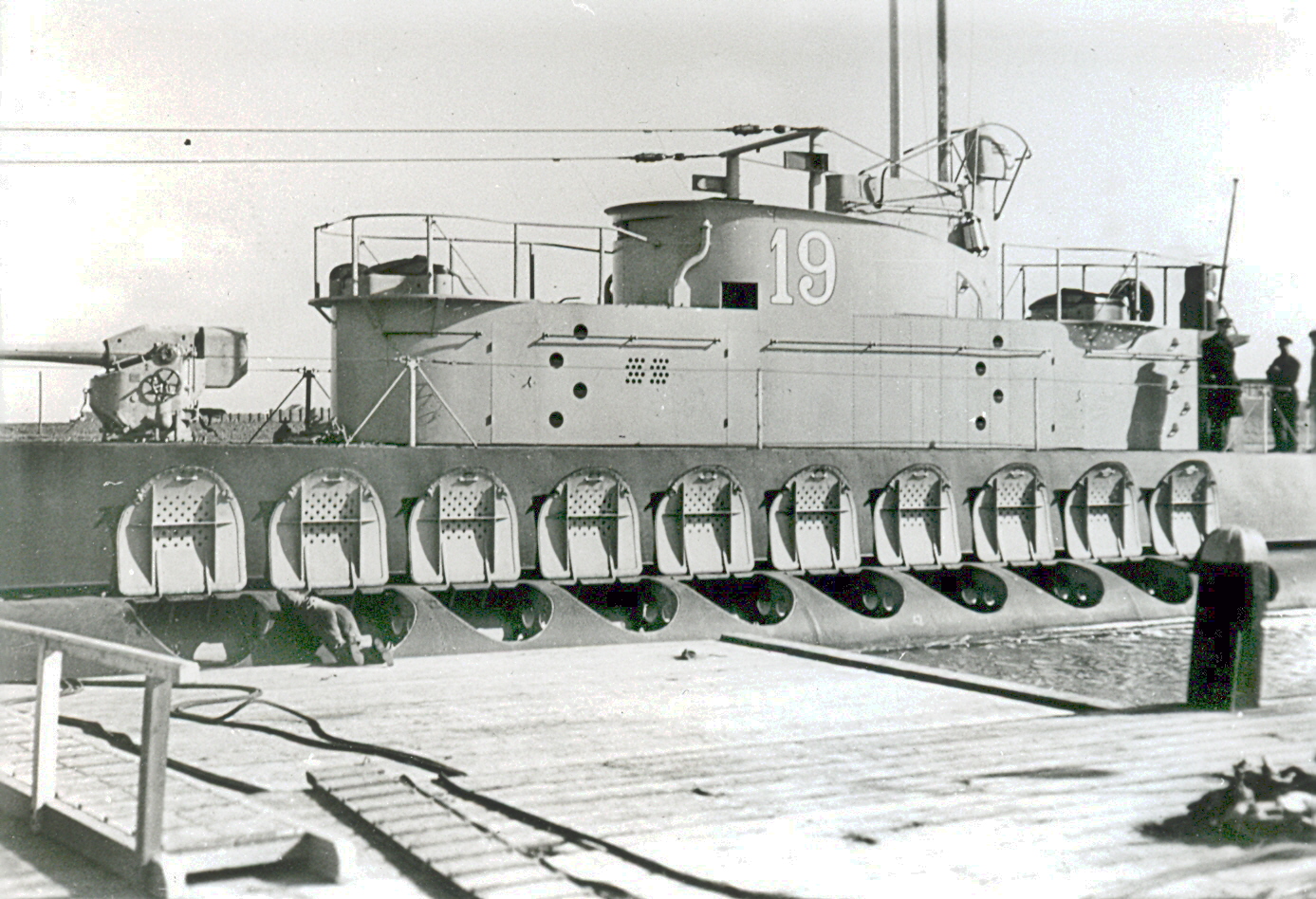
Greetings to Elia, Popeye, Banyan, Sjors, Anthony, Ian and Boris and thank you all for dropping in. Did you get enough beer and popcorn? Sjors was buying @ Ian, you know, our daughter is still talking about it and planning to build that railroad. She and I designed a nice little mining and lumbering layout, with a small river loading dock! As far as the mine issue goes, it's really tempting but let me get my head wrapped around drawing up the plans for the con first, then we;ll see - - - - or sooner @ Boris, yes, thanks for sending these, they are great and add to my collection. I have send you also a few pics I found in my files and the digital pics Remco send me from the Navy Archive. You could machine them from copper or wood or sculpt them from Sculpy. I'm waiting for the copper that Paul mailed to me and will try to use that. @ Popeye, thanks for looking. Remco also came up with an idea and we are looking into that as well. Fortunately there are only a few letters and numbers I need The small ones at the bow for the load levels are the ones that can be gotten from model railroad places. Well, today was also a day away from the shipyard. Went to our monthly colored pencil society chapter meeting and then mowed our backyard lawn. Besides the mine issue I am also in a dilemma about the bow side anchor. Remco went to the Navy Archive and could find nothing on that anchor but according to three photos I have there seem to have been a small standard anchor. I'll show the pics below. I won't cut into the side of the deck structure until I have something more positive on the anchor. I think that this will also be guesswork but as long as it looks similar to what I see on the photo then I'll be happy. I'll also add a few pics of mines being loaded. These are training mines by the way. This too was not a simple procedure. This shows the O 19 surfacing after a test dive in Scotland after she was overhauled in 1944. When you enlarge the picture you should be able to see the bottom of a small anchor. This is what I think this anchor could look like. This is another example of the type anchor they could have used, much smaller of course. Cheers,


-
Hello Cees and Pollex, thanks for dropping in. @ Cees, thank you for your kind words. The length is supposed to be 165 Amsterdam voet, beam of 41 A'dam voet and the hold is 16 voet. I think I have written this in my intro on page 1 with some other stuff. @ Pollex, thank you too for dropping in and your questions, appreciate it. About the steps, well, yes, this may not be as the English ships would have it but, if you have read my intro you may have seen that this is a hypothetical ship. As the shipwright, owner and captain I have taken certain minor liberties with the design. Also, this design is based, or closely so, on Dutch merchant ships of the mid 17th century, not English. And remember, it's a merchant ship not a naval war ship, although they have been "rented" by the navy to battle their enemies at that time. I have also looked at many paintings and drawings of ships of this era and have seen variations in details such as this. There were and still are no plan drawings of these ships and the ship yards of the 7 chambers of the VOC build their ships their way, not bound to one standard. Although van Ijk and Witsen wrote very comprehensive treatises on shipbuilding. Right now the best anyone can do is take off the lines of old models that hang in churches and museums and use these models and the drawings and paintings as a guide. As the designing shipwright, builder and owner I wanted a hybrid. I.e. a heavily armed merchant vessel to combat the many pirates in the Indonesian archipelago and of course the Portuguese and with a good cargo capacity. That's my excuse anyway Will it suit my model? Yeah, I think so. I designed and am building it for my pleasure not so much as making it authentic, which is impossible anyway. As long as it looks like and could function as a mid 17th century Dutch merchant ship the VOC would use then I'm happy. Much more can be said but I think this should answer your very legitimate question. Cheers,
-
Hello Freek, Fascinating project! I'll draw up a chair and watch the build. Cheers,
-
Well hello Lawrence, good to hear from you again and thanks for dropping in. Yes, I guess I'm adding more things to this build then initially intended but I like the way she is turning out. Right now she is put on the back burner in favor of de model of my father's submarine, the O 19. Sooner or later I'll get back on the VOC ship Surabaya. Cheers,
-
Thanks again everyone for dropping in and your kind remarks and "like" votes. Today was a research day thus no shipyard work. @ John (texxn5), yes, it's tempting and not out of the picture. It's not as simple as all that you know. There is nothing behind the outside planking and I have to simulate a part of the pressure hull too and have nothing to attach it to. The side frames are equally difficult to get in through that small hole. We'll see. @ Mark, thanks for your approval of the torp tubes. Yes, the mine tube can go all the way to the bottom, that's not my biggest problem, it's what I mentioned to John. I need to think about a method that can accomplish it without doing any damage to the hull. Hmmmm, foam there is already foam inside but we could scoop some out and redo it - - - - - and - - - I'm thinking - - - - I'm thinking - - - - @John (Lad), right, easy peasy right??? Yes, the idea was to do it with just one mine tube. I have the specs for the mines and several photos, that's not a or the problem. @ Boris, yes indeed ! My face is red from embarrassment Just not paying attention, but this is an easy fix If all my errors are this simple - - - - @ Michael, thanks for the info, appreciate it. Remco suggested to make my own decals by printing it on decal "paper" or whatever it's called. I'll certainly look at model railroad decals. That'll be good for the small numbers but the large letters and numbers for the con may not be available. BTW I love model railroads our daughter and I were at one time building a nice N gauge layout on a 4 X 8 framed table. Oh well, things got in the way and the trains are in a box in her garage for the last 34 years, Wow, how time flies. Thanks again all y'all for your encouraging words and help. Now I need to get busy with drawing up the plans for the conning tower. Cheers,
-
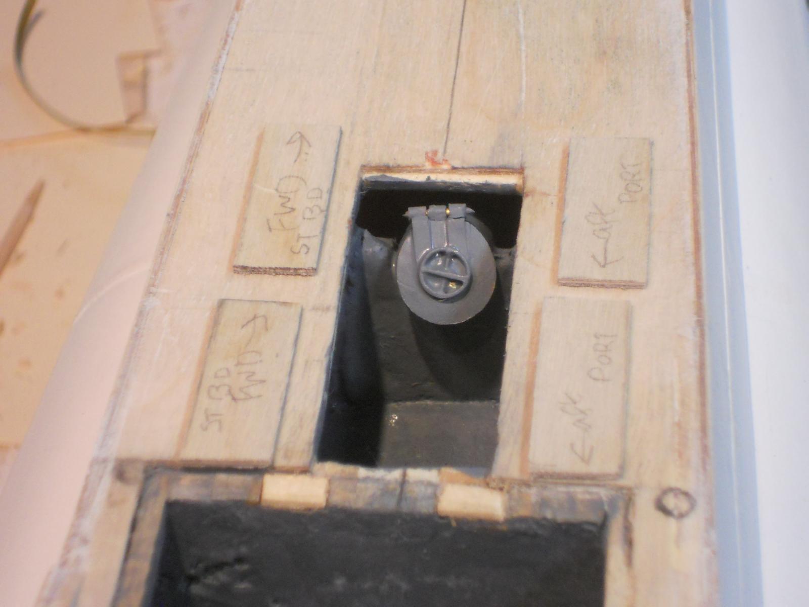
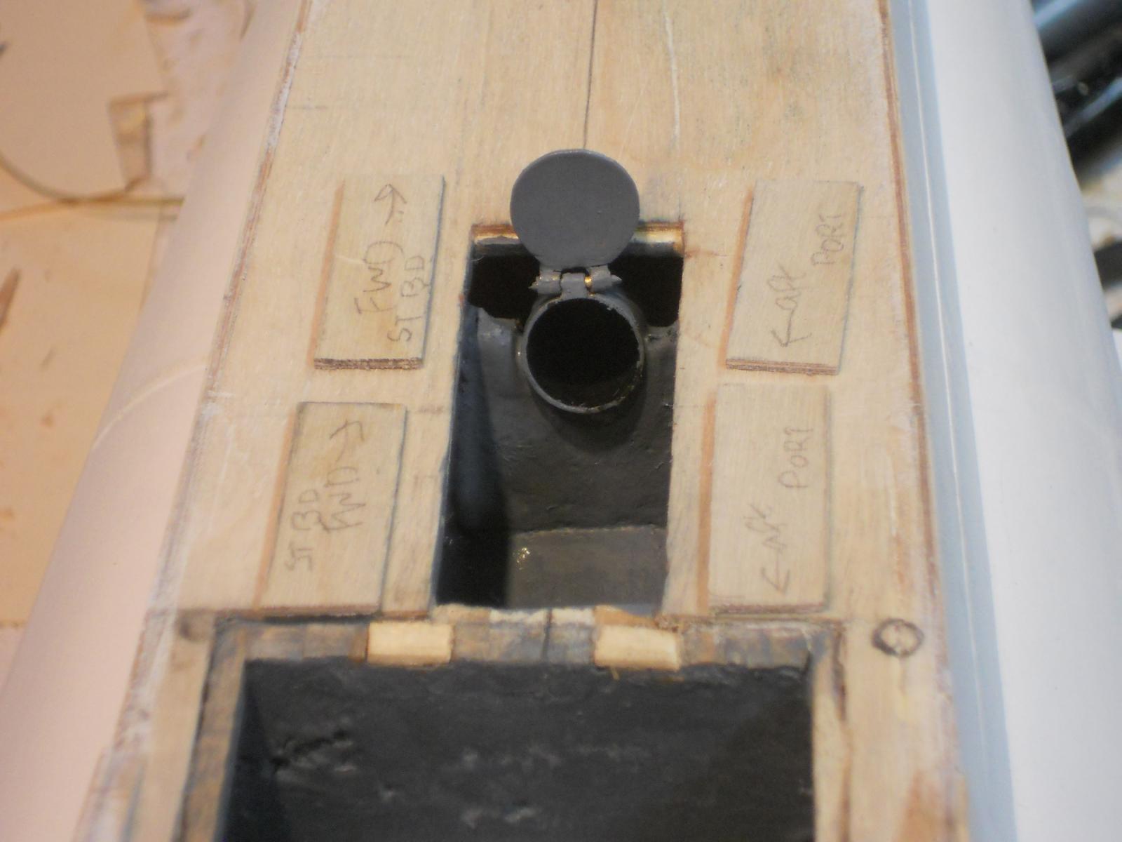
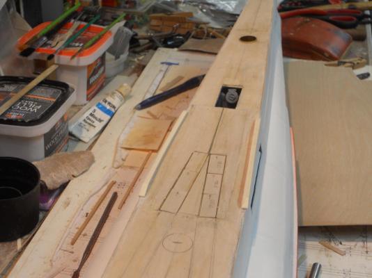
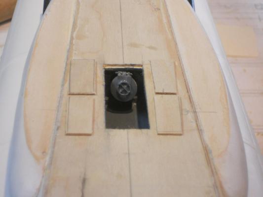
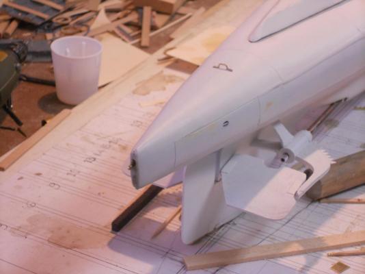
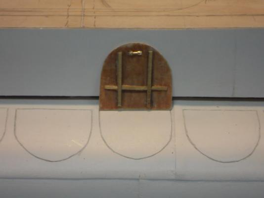
Hello again friends, Today was more exploration of the conning tower. Instead of just building the con without any working detail I "conned" myself into going hog wild. That's why I am now taking my time to draw up the basic build as "plank on frame". I must be sure about where all the detail stuff is placed and the measurements. I'll have to go back to my drafting table and lay things out for this build. It's like Remco's mantra, treat each part as a model. In addition to more thinking and sketching I painted both the stern and bow torpedo loading wells and tubes. I also made the stern well hatch doors. Then, in my sketching the conning tower I determined that I had to remake the dingy loading boom, which is also the center support for the hatch covers. I have no detail drawings for this thing but have a fair idea how it could have been done. For the model it'll be attached to a rotating pin at the aft end of the conning tower and can also be rotated out of the dingy compartment with a bolt through the rotating pin assembly. The other end will have a place for a sheave and tackle and a latching hook for the lift cable. I also made two of the stern mooring thingies. Well, that's about it and below are a few pics of today's progress. This is the stern torpedo loading tube installed and painted. The entire well is painted dark grey. This is the bow torpedo loading tube installed and painted with the pressure door closed, as well as the entire well area. This is the bow torpedo loading tube installed and painted with the pressure door open. Here are the two mooring gismos at the stern. Just for doing something else I made the lid for the mine tube bins. Still tempting to actually cut a hole in the poor boat and install a tube with a model of a mine. Just too much work, the area inside was not build with that in mind and it'll require a lot of very difficult work to make it look right. It's like doing an appendectomy through your nose. But then again, who knows, I love a challenge. Don't get your hopes up too high John This is a copy of a photo I have of the O 19 with all the mine bins open. I modeled my lid after this picture. My question is this, if anyone can lead me to a place that sells letter and number decals that look like these I'll be mighty obliged. I also need Roman numerals for the draft markings. Cheers,


-
Hello Popeye, John (texxn5), Daniel, Remco, Mark and Anthony for stopping by and your kind words. @ John, yeah, there is always a way to skin a cat but I have to be extra diligent in drawing up the build of the conning tower. There are other details involved and this time I can try to anticipate the correct location of all the "stuff" that's involved with the con. It'll be more like a "plank on frame" job. @ Popeye, please don't sell yourself short my friend, you do some awesome stuff with your builds Thank you for your encouragement, I really appreciate your comments. More to come later. Cheers,
-
Hi John, ol eagle eye Popeye strikes again I looked at the pic too and din't see it. I guess I wasn't looking for it. Hey, stuff happens Strange helm arrangement on this ship but it works. Cheers,
- 2,250 replies
-
- 1
-
-
- model shipways
- Charles W Morgan
- (and 1 more)
-
Hello everyone and I trust all y'all are doing fine and being in good spirit. @ Mark, locks on the hatch doors? They have locks? Oh noooo, more work, hinges and locks. I thought locks is a preserved fish Oh, sorry, different spelling. Talking about hinges for the hatch doors I am making, I need 25 pair. They are to be made from 1.5 mm brass tubing cut into 1 mm small pieces. That makes 50 of these little buggers. That'll keep me out of the bar @ Daniel, painting the tubes and locking wheels is coming soon. All of the "stuff" inside the wells will be painted dark grey. I'll leave at least one well and door open showing the loading of a torpedo. I think it'll be the forward one. @ Adriaan, thanks for your approval, yes, I'm happy with the way they turned out. @ John (texxn5), thans John. Yup, I have figured out how to make the AA guns retract into their-water tight pressurized tubes. how? Glad you asked - - - - - first I insert a brass tube into the pressure hull with the end even with the top of the pressure hull. The length of it must be long enough for a second tube that can slide into the lower tube, much like a hydraulic car lift. On top of the second tube will be a cross beam to keep it centered and the base for the AA guns. This way the gun can swivel up and down and rotate horizontally. Now, that's what I see in my mind right now. Next I'll have to make a work sketch and put some measurement on it. I just bought a few brass tubes for this project as well as a few smaller tubes for the periscopes. Hmmmmmm, yea, they'll retract too @ Remco, Sinter Klaas? Oh my, I have not been a very good boy this year - - - - I hope "Zwarte Piet" wrote all my bad things with invisible ink I hope you realize that I didn't mention it as a hint - - - but it would really be great to know what sort of anchor they used on the side. @ Ian, well, that's what happens when you go away for a week and don't log in to MSW. Things change rapidly. Well, this morning I had to remake the stern loading tube and grind some more wood away in that area. Took me about an hour total. Both tubes are now cemented in place and I can paint the wells and tubes. Tomorrow we'll have a few pics. I have drawn the outline of the con on top of the deck but I may have to make it a tad narrower yet. I'm following the deck layout drawing I got from Gino. First I used the O 21 model drawings I bought through Remco but the O 19 and O20 seem to be narrower then the later subs. Hey, I am also learning about subs, I'm an airplane guy I'm still waiting on my 17 mm tubes for escape hatches. As mentioned a few posts ago, I will be making my own AA pressure tubes from flat stock. I don't see paying $25 for shipping. I also started with the net / cable cutters for the bow. Well, that's it for today. Thank you all for joining me on the build of my father's boat, the O 19. Cheers,