

BIGMAC
-
Posts
50 -
Joined
-
Last visited
Content Type
Profiles
Forums
Gallery
Events
Posts posted by BIGMAC
-
-
-
-
-
A square is a parallelogram as well as being a rhombus and rectangle or so that old geometry teacher taught us
 The angle at the corners can be anything, including 90 degrees. As long as the opposing sides are parallel to each other and of equal length and the opposing angles are of equal measure it is a parallelogram. Is this stuff useful? Sure, but did I enjoy the classes? Not as much as history and geography!
 Allan
agreed!!!! even if the angles are 90, it is still a parallelogram.....
-
Mac,
Yes, it is 'C".
A parallelogram is a closed structure with two pairs
of parallel lines. The sides are parallel and the top/bottom
are parallel. They meet at something other than 90 degrees.
If they meet at 90 degrees, they have a special name: square/rectangle.
Thanks Jaager....I got what u mean. Just to add here that the exact is "'A Parallelogram is a flat shape with opposite sides parallel and equal in length."' which means that squares and rectangles are Parallelograms too. A parallelogram where all angles are right angles is a rectangle.
-
In the case of parallelogram-shaped ports, the lid hinges were arranged to pivot in a horizontal plane. One hinge's axis would be located slightly higher above the upper edge of the port. Thus the lid could open and shut without binding.
Hi Druxey...do you happen to have a close-up drawing of this??
-
I am pretty sure that the gun ports are parallelograms.
The frames define the sides and the deck decides the
sill and lentil.
If you look at framing diagrams of
English warships of the 18th c and 19th c you will
see that they used some fairly elaborate positioning
to shift their frames so that whole timbers made up
the sides. From my observations, the French and
Americans rolled the dice and cut into the timbers to
get the gun ports where they wanted them. Or let
the frames define the gun port location.
Hi Jag....Saying parallelograms, you mean Diamond shaped as in case C?
-
First the most important question: What ship/era/nationality are we talking about :-)
It is he most common during the later times - as druxey and others point out - that the sides are vertical and bottom and top follow the line of the deck.
This allows the frames - which were build vertically - not to be weakened by cut outs and also gives the same height level towards the deck and also allows the spriketting to pass uncut underneath the ports.
This applies for carvel build with frame first and vertical frames.
Now the "it depends": Older ships build hull first - like Vasa or contemporary dutch builds - where the frames were afterwards applied into the hull and were not vertical, pointing towards the ship´s middle on the top, thus resulting in tilted squared ports like #D.
XXXDAn
Hi dafi.......its about a late 18th century Mediterranean Brig
-
Have a look at the NMM plans section - you can see the ports are almost invariably vertical sided with various angle top and bottom depending upon position along the vessel
eg http://www.rmg.co.uk/sites/default/files/styles/slider/public/images/J4207.jpg?itok=if47AICt
( I have always wondered how the port lids were hinged when they were slightlyt diamond shaped !!)
Thanks Spy .......and !!!!! I have exactly the same question- how do the hinges work!!!!!! I was thinking, maybe the upper side remains parallel to the waterline and the lower side is inclined...maybe
- thibaultron and mtaylor
-
 2
2
-
Usually the sides of the ports were vertical, as you have in 'C'. However, depending on the ship, if there were drag (floating lower at the stern than bow) the ports would appear as if 'leaning' backwards. The frames were normally set upright on the keel, the sides of the frames forming the sides of the ports.
Thanks Druxey.... So you say C is the correct one?
- mtaylor and thibaultron
-
2
-
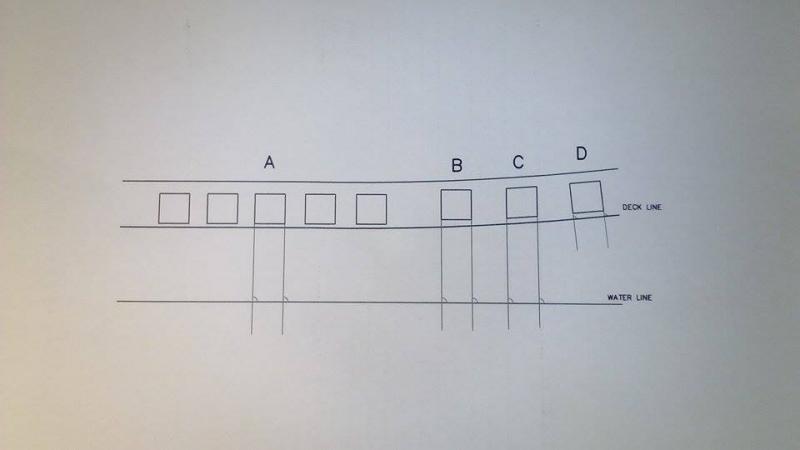
Not sure which one of B, C or D is correct....
A...Deck line parallel to water line...Ok, thats easy. Just a square.
In cases B, C and D, the deck line not parallel to W.L.
B is like A....the left and right sides vertical to the Water Line, up and down parallel to the W.L.
C has left and right sides vertical to the Water Line, up and down parallel to the Deck....Not a square. No right angles.
D is a square with left and right sides "vertical" to the Deck Line, up and down "parallel" to the Deck Line.
Think D is the correct one, not sure though........
Any Advice pls?
Thanks,
Mike.
- GemmaJF, WackoWolf, thibaultron and 2 others
-
5
-
Hi there Big, and good luck with your project.....Is this a scratch or a kit? what scale? ...and if it is a kit, which one please? Thanks!!!!
-
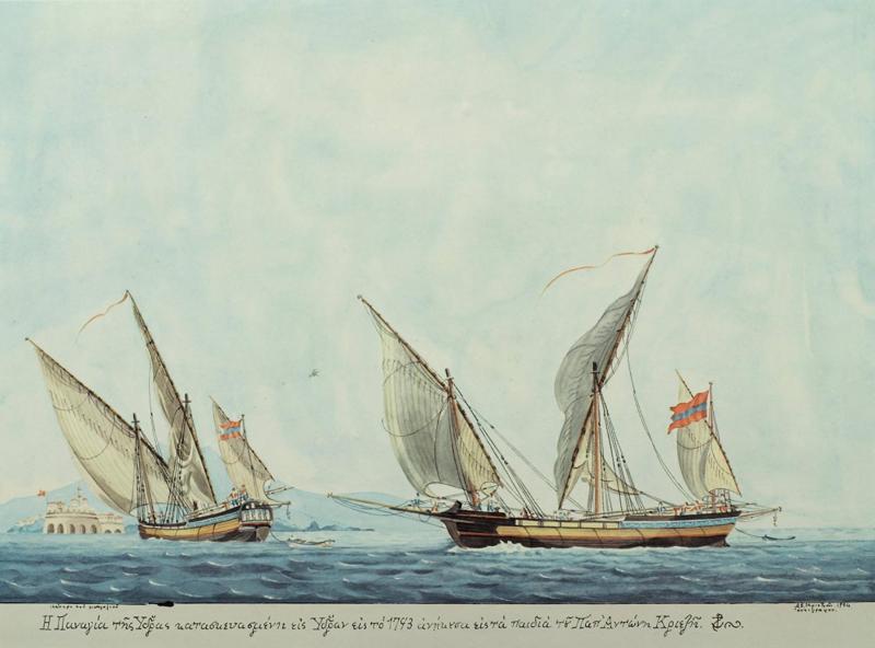
Hello all.Portuguese fishermen might still use something similar, not to say the same at least at the end of the stem of the galliot bow.From the photos I guess that, either they were using something made of rope like the "baggywrinkle", or they might would cover a proper wooden shape, with a sheepskin. That would explain what it seems like heavy load at the edge of the yards.What remains, is to ask a Portuguese fisherman, about the name or even the construction of that.
 Thx
Thxmany thanks Thanasis......one would expect to be widely used, even in present day, in the Mediterranean area, but I dont recall to have seen it anywhere.
-
Hello,I must say that I have never met the name of the accessory that is quite common in Latin rigging. Present at the end of the yards but also on the head of the bow for the same purpose: to save sails.This element could it be a wooden disc as it would appear on some drawings? Why not but I doubt because the weight of such a disk would bend the yard.Concerning the curvature of the yard, it's natural and due to the weight and the flexibility of the yard wood (pine).For huge galleys yards I studied, the "comite" or executive chief of the galley (that is, among others the function, sail master), takes the curvature into account when cutting the sails. The arc of this curve is, at rest, between 3 and 4% of the length of the yard so about 3 feet to a yard of around 100 feet for the longest of them.With the wind, the rope retaining and swelling of the sail this curvature increases.Regards,Gérard Delacroix
thanks Gerard, great piece of info!!!!
-
I have continued digging as time allows, but surprisingly little detail accessible (that is the operative word) concerning the actual manufacture of the spar. I can find a huge volume concerning the evolution and dispersal of the rig, and some tantalizing tidbits that I can not access (see, for example, Landström, B. 1961. The Ship: An Illustrated History for what is purported to be a good description of how the lateen sails were handled).
I would suspect, based solely on the visual evidence of the attachments (on galliots, galleys &c.), that they were indeed sometimes of other than sheep skin. Rounded wooden "caps" would offer nearly similar protection (the purpose being to protect the aft sail from damage).
Think so too. seems practical and logical I guess...
-
The descriptions of how these rigs were operated would tend to support a designed curvature. The optimum location for the sail is on the leeward side of the mast so that it is pushed away from the mast, filling and using the most available sail volume. In order to accomplish this, the yard would need to be brought to the other side of the mast. One (probably most common) way this was done was to bring it to a nearly vertical position then physically wrestle the yard to the other side of the mast. The curved yard would ease this by keeping the ends away from the mast, avoiding (or at least reducing) interference with the mast itself as well as shrouds.
See Campbell, I.C. 1995. The Lateen Sail in World History. Journal of World History 6, no. 1: 1–23. http://www.jstor.org/stable/20078617as well as Castro, F., N. Fonseca, T. Vacas, and F. Ciciliot. 2008. A Quantitative Look at Mediterranean Lateen- and Square-Rigged Ships (Part 1). International Journal of Nautical Archaeology 37, no. 2: 347–359. http://onlinelibrary.wiley.com/doi/10.1111/j.1095-9270.2008.00183.x/abstract (available at http://nautarch.tamu.edu/shiplab/00-pdf/Castro%202008%20-%20IJNA%20-%20Lateeners%201.pdf )
Many thanks Wayne for your time.....and excellent references!!!!
-
The beauty of the internet and the great collective experience we have on this site - thanks for the explanation Gerard (we learn things every day) and thanks Big Mac for raising the sugject.
cheers
Pat
Thats right Pat and I thank everybody for their thoughts and time.......BUT, nobody answer my second question
 .....(Furthermore, the curvature of the spars/yards was "build in" or they were very flexible and it was due to the force of the wind?).....
Mike.
-
Hello,
This "object", which is composed of a large piece of sheepskin with its all its wool, is designed to avoid tearing of the back sail by the top end of the fore yard when they are handling. This yard end is very flexible.
The great latin sails are succeptibles to many positions to function properly, this involves yard movements sometimes poorly controlled with high winds.
The bottom of the yard is often equipped with this accessory but this part is more controllable because it is steeper and it is headed by a rope.
Regards,
Gérard Delacroix
2 quick ones Gerard......1) is there a name for these objects?.......2) do you think that, as an alternative, they maybe use a wooden ball-shaped part, instead of sheepskin?
Thanks and Regards
Mike
-
Hello,
This "object", which is composed of a large piece of sheepskin with its all its wool, is designed to avoid tearing of the back sail by the top end of the fore yard when they are handling. This yard end is very flexible.
The great latin sails are succeptibles to many positions to function properly, this involves yard movements sometimes poorly controlled with high winds.
The bottom of the yard is often equipped with this accessory but this part is more controllable because it is steeper and it is headed by a rope.
Regards,
Gérard Delacroix
Great!!!!! Many thanks Gerard!!!!
-
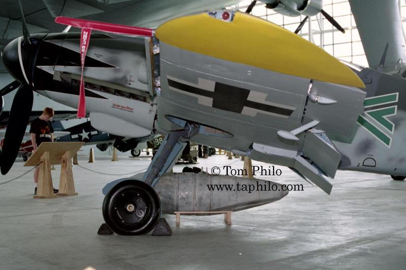
On the funny side. Friend called me and congratulated me for the first ever (he says) aircraft photo on this site....
....and without being out of context!!!! (he says) -
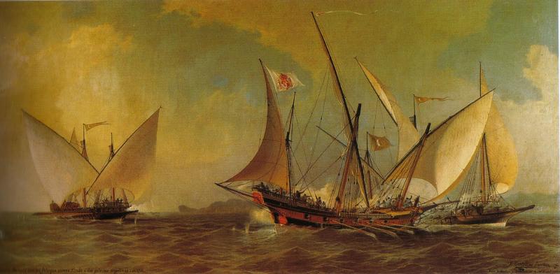
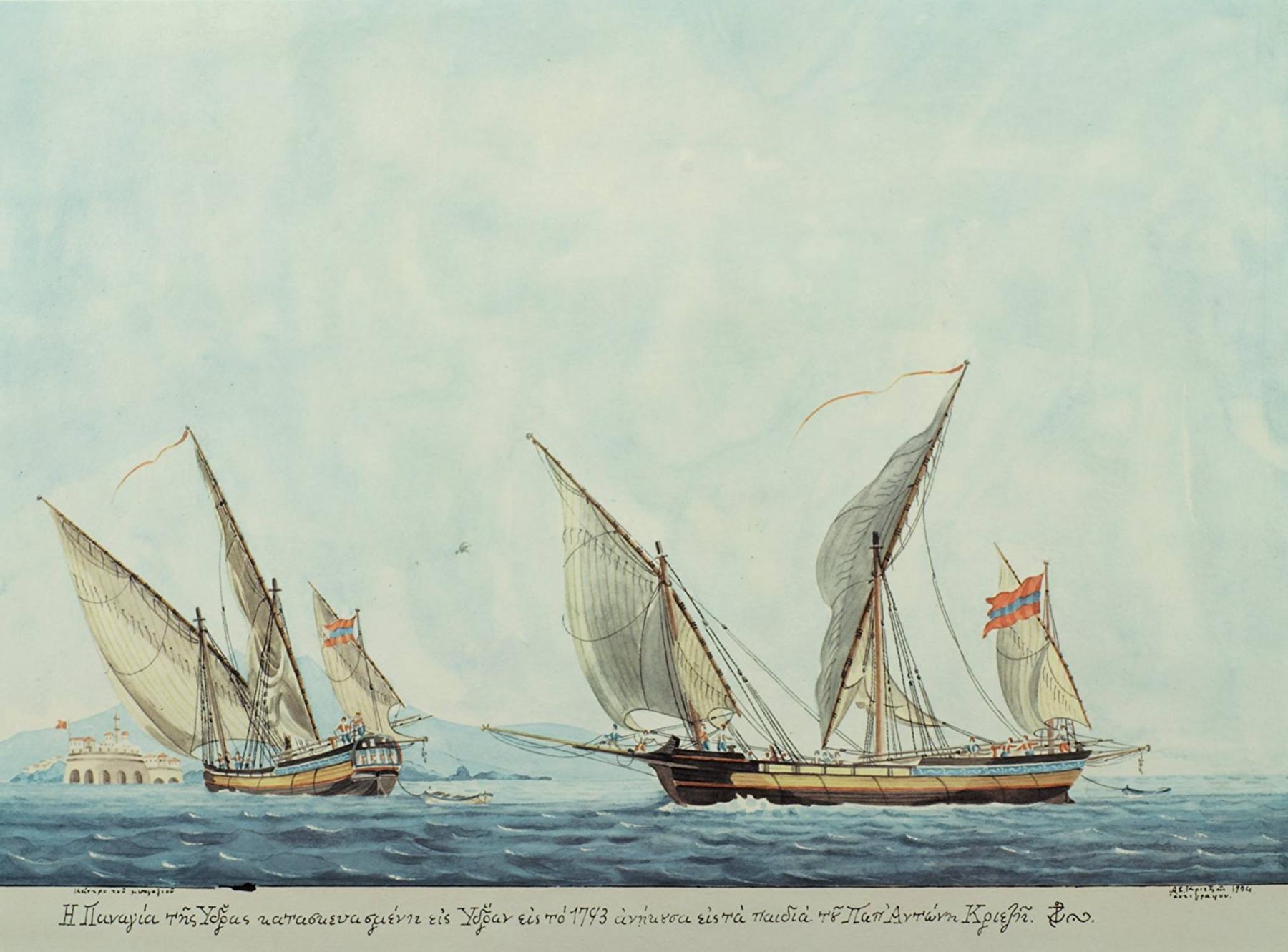
Not really getting much closer concerning the function, however the object in question is hardly unique to the galleot. Note the 2 images below where Steel shows a similar appendage on the Xebec and the Pink.
Decidedly not a sheave (block, pulley &c.). No lines evident in any of the views, yet control lines are visible along the lateen yard.
May want to take a look through some of the history of fore and aft rig resources out there (Chatterton, Leather, R.C. Anderson) for descriptive information.
Very interesting photos Wayne. Thanks alot. You are right, not only in galleots. I think that has something to do with Lateen sails and their handling. In some cases there are not appearing, but maybe there are just omitted by the artist
.
- mtaylor, popeye the sailor and BANYAN
-
3
-
Greetings everyone;
With regard to this object being a counterweight, I do not think this is very likely, as it is on the longer part of the yard. A counterweight would need to be on the shorter part to balance the additional length of the longer arm. At least, if it was countering the weight of the yard this would be so. If it was somehow intended to counter a force exerted by the wind this could be different, but a rope would seem the easiest way of countering the wind.
Would a weight at this point be advantageous or disadvantageous when changing tack? How is a lateen sail handled when manoeuvring?
Could it be intended to act as a damper, taking some of the spring out of the yard that could arise due to its length, especially during a change of tack?
There is no sign of any rope reeving through it on any of the illustrations shown (although that could, of course, be artistic licence) so a truck for flag halliards seems unlikely. Especially as one vessel is shown with a flag at the masthead. Although, certainly, the absence of flags from the yard-arm does not prove anything in this case.
More food for thought, I hope.
All the best,
Mark P
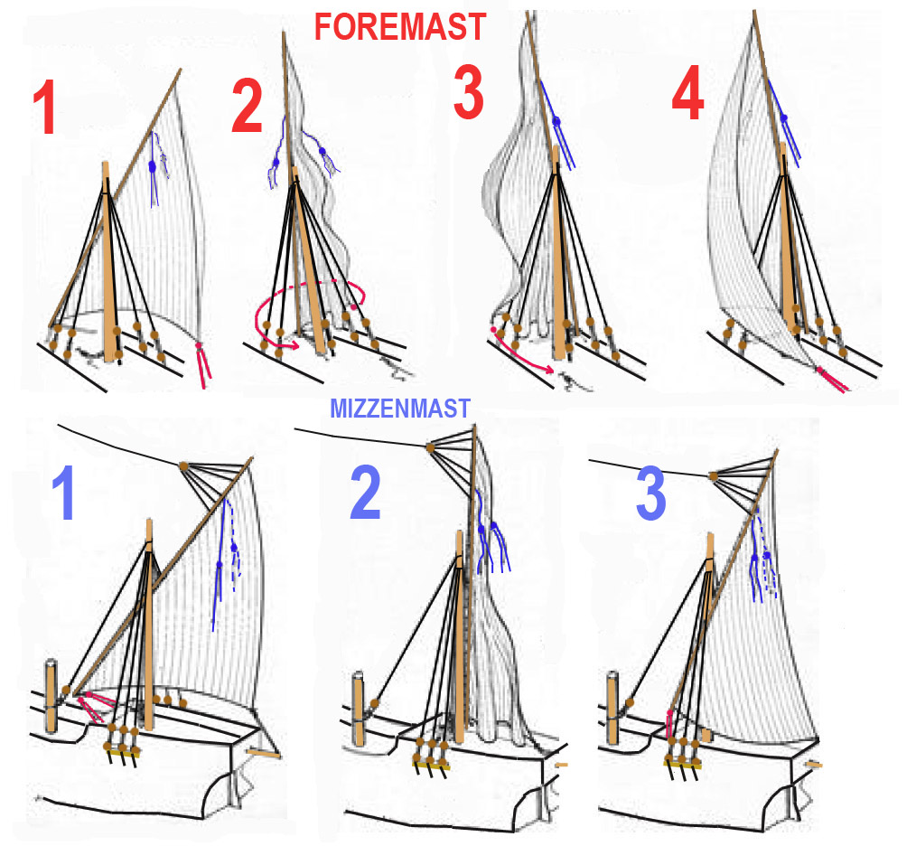
Thanks for your interest Mark. Indeed many question marks. During my pre-building research, I have saved this graph of a lateen sail handling (its from a building post on this site, unfortunately dont remember which one), but i dont find any answers yet....Dumper? buffering control?

-
I like the idea of the counterweight/buffering control. Kind of reminds me of the horns on the flight control surfaces of aircraft wings, which, I think, are there for buffering control. Maybe......

-
Could they simply be a large counterweight (cantilever)? The last image is not that clear but appears to have only a tackle on the opposed side? the weight would then assist in the working of the yard???? Only conjecture offered for further discussion.
Cheers
Pat
Hmmmm, Interesting thought Pat. Thanks alot!!!!!


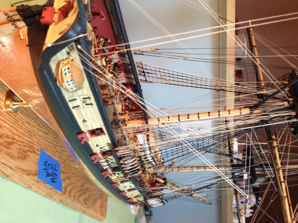
US Brig Syren by Gahm - Model Shipways
in - Kit build logs for subjects built from 1801 - 1850
Posted
Hi Gahm...E X C E L L E N T build!!!!!!! I have the kit and it is prop my next one. Being in the study phase, I wonder if you know whats the use of the quarter galleries, since there is no space behind them on the deck, or any kind of door at least. Thanks for your time. Mike.