Jaekon Lee
-
Posts
110 -
Joined
-
Last visited
Content Type
Profiles
Forums
Gallery
Events
Everything posted by Jaekon Lee
-

HMS Alert 1777 by Jaekon Lee - 1/64
Jaekon Lee replied to Jaekon Lee's topic in - Build logs for subjects built 1751 - 1800
Thank you Mark. Yes, I,d like to full planking in and outside of port side. Starboard side will be left unplanked except wale and reband. Lee -
HMS Alert 1777 by Jaekon Lee - 1/64
Jaekon Lee replied to Jaekon Lee's topic in - Build logs for subjects built 1751 - 1800
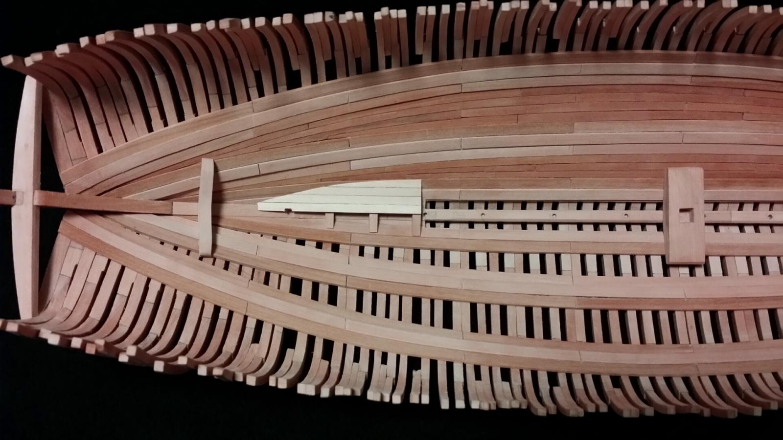
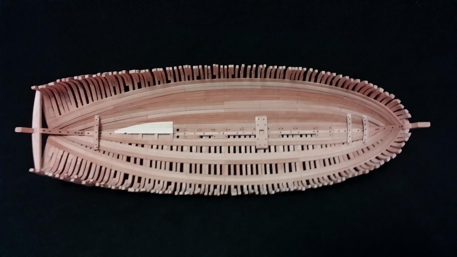
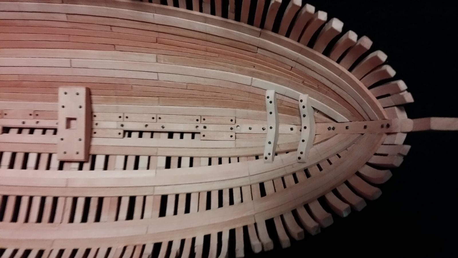
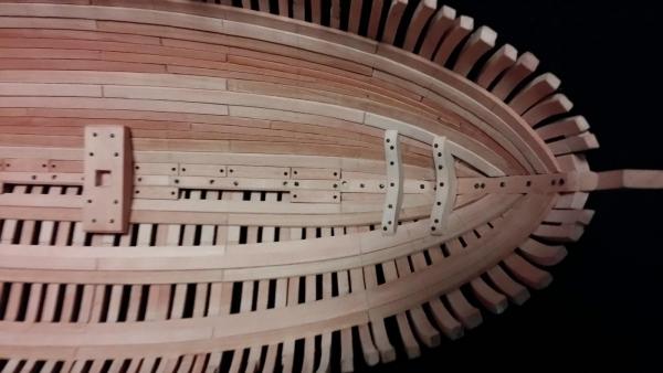
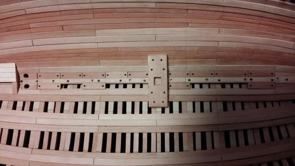
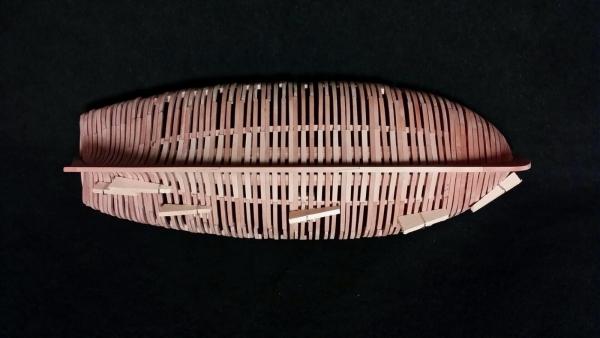
Port side inner hull planking, limber board and bolting Inner hull between thick stuffs of port side were planked. Planking boards were tapered and dropped at the ends of fore and aft. To simulate bolting, blackened steel pins were nailed. Two kinds of bolt heads, square and round size of around 1mm, were tried but they seem to be oversized in this small scaled ship.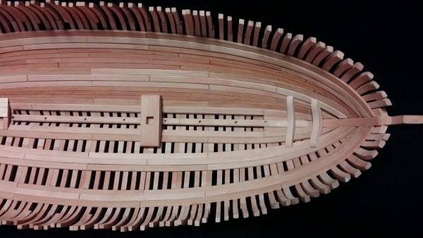

-
HMS Alert 1777 by Jaekon Lee - 1/64
Jaekon Lee replied to Jaekon Lee's topic in - Build logs for subjects built 1751 - 1800
Many thanks Antony for your kind words. I learn lots of skills and tips from the logs of this forum everyday to bring her up. Merry Christmas and Happy New Year. Lee -
HMS Alert 1777 by Jaekon Lee - 1/64
Jaekon Lee replied to Jaekon Lee's topic in - Build logs for subjects built 1751 - 1800
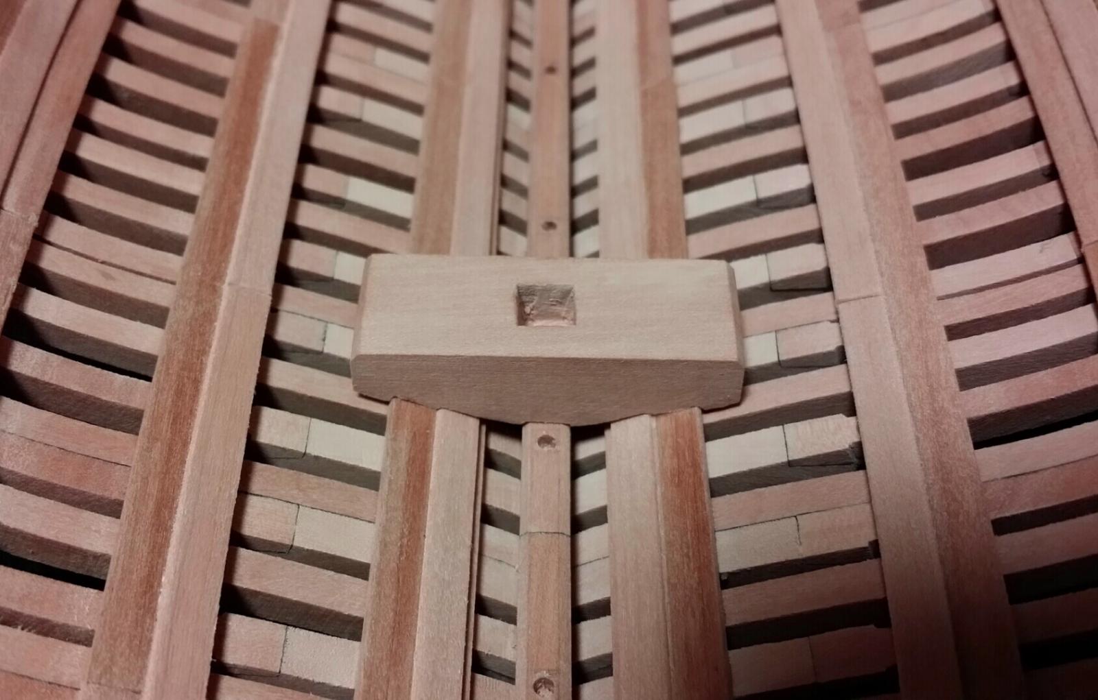
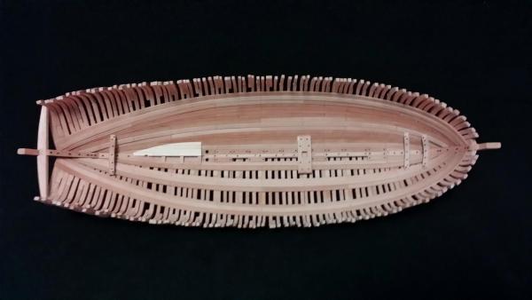
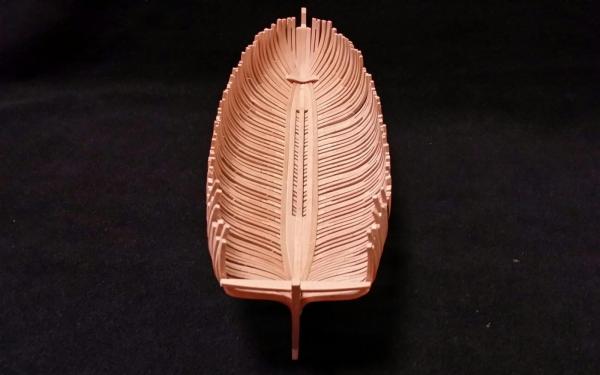
Thick stuff, footwaling, mast step, hooks and aft magazine I decided to plank only the port side to see the inner parts after finishing this ship. As one trial, half of aft magazine platform was planked. To get some contrast, I choose lumber of bright domestic pear wood for the planking board. Cheers,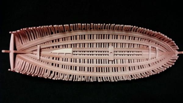

-
HMS Alert 1777 by Jaekon Lee - 1/64
Jaekon Lee replied to Jaekon Lee's topic in - Build logs for subjects built 1751 - 1800
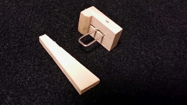
Tip - Joining Clamp In this small scale model, the spacing between frames is very narrow, sometimes less than 1mm, holding parts after gluing is somewhat difficult. For this, I made special clamping tool and found that it is quite useful and handy, so I introduce it to all. As can be seen at last pic, it can be made easily with paper clip and small wood block and wedge without special tools. Cheers

-
HMS Alert 1777 by Jaekon Lee - 1/64
Jaekon Lee replied to Jaekon Lee's topic in - Build logs for subjects built 1751 - 1800
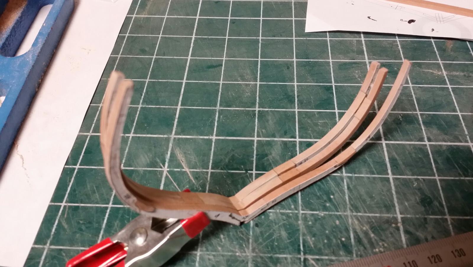
Many thanks Nils for your compliment. Small update today. Lower thick stuffs are added with steam bent long strakes. She becomes stronger day by day.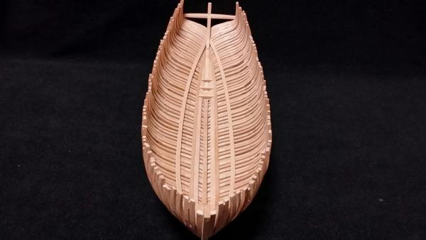
-
HMS Alert 1777 by Jaekon Lee - 1/64
Jaekon Lee replied to Jaekon Lee's topic in - Build logs for subjects built 1751 - 1800
Thank you Christian. I sincerely appreciate your comments. By the way, it would be another question, why Goodwin drew this odd shaped design? He is responsible for this as an author of book. Is there any one who can get in touch with Goodwin? -
HMS Alert 1777 by Jaekon Lee - 1/64
Jaekon Lee replied to Jaekon Lee's topic in - Build logs for subjects built 1751 - 1800
Hi, Allan. Thank you for your interest on my building log. I'm following the plan of "Anatomy of the Ship" series written by Goodwin. Yes, there are evenly spaced 6 gun ports at each side of hull and also, some of top timber are used as the post supporting the sheer rail. In my understanding, the shifting of top timbers is assumed to accommodate the mismatch of gun port and frame position. Anyway, it is quite unique frame design. Lee -
HMS Alert 1777 by Jaekon Lee - 1/64
Jaekon Lee replied to Jaekon Lee's topic in - Build logs for subjects built 1751 - 1800
Hi, Mark. Thank you for your kind comments. I've reviewed some logs in this forum to get the answer and found that the clutch and breast hook placed over the planking from the log "HMS Naiad" by EdT. So I'll de-bond the hook and score the bottom to fit to the profile of planking boards. Lee -
HMS Alert 1777 by Jaekon Lee - 1/64
Jaekon Lee replied to Jaekon Lee's topic in - Build logs for subjects built 1751 - 1800
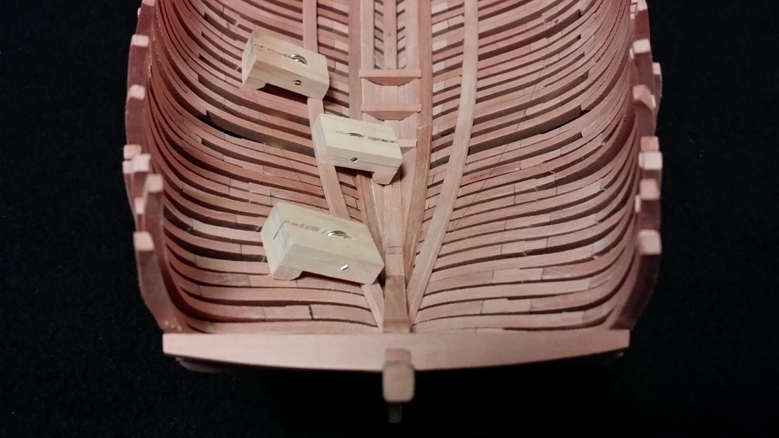
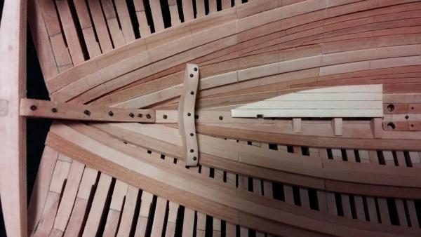
Thank you for kind words, John. She is growing every day. ♡♡ I have a question to all. Is the crutch or breast hook joined directly on the frame or on the inner hull planking board? I think I made a mistake as shown on the photo.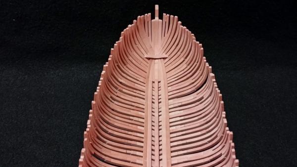
-
HMS Alert 1777 by Jaekon Lee - 1/64
Jaekon Lee replied to Jaekon Lee's topic in - Build logs for subjects built 1751 - 1800
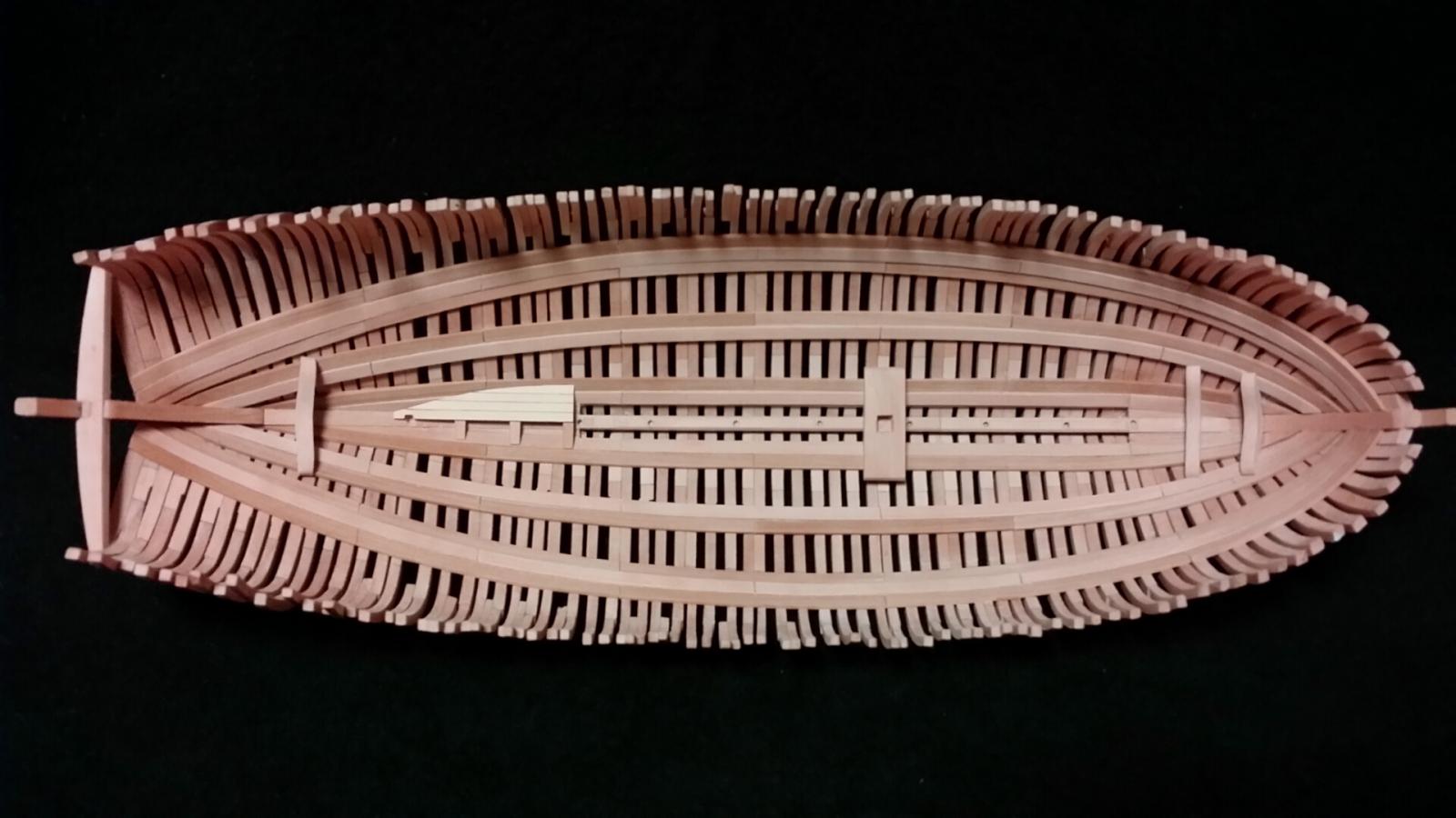
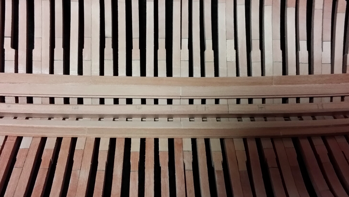
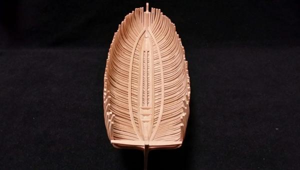
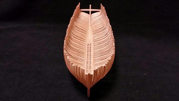
Keelson and limber strake Small update by joining keelson and limber strake but, the structure became a little stronger one.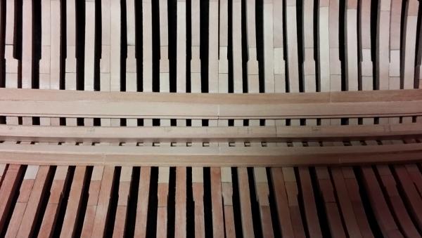
-
Mary Rose 1545 by tarbrush - Scale 1:72
Jaekon Lee replied to tarbrush's topic in - Build logs for subjects built 1501 - 1750
Hi, John. You are building very attractive ship. I hope you can fix the problem soon and enjoy the following works. Merry Christmas. Lee -
HMS Alert 1777 by Jaekon Lee - 1/64
Jaekon Lee replied to Jaekon Lee's topic in - Build logs for subjects built 1751 - 1800
Thank you for kind comment, Mark. I agree with you about the importance of frame alignment. I've thought about using base plate with squaring jig but I concluded it would be useless due to the irregularity of frame shape. Fortunately, frames are flexible enough, I'll try to adjust frames to keep alignment and symmetry during joining cross members. Lee -
HMS Alert 1777 by Jaekon Lee - 1/64
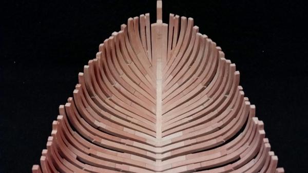
Jaekon Lee replied to Jaekon Lee's topic in - Build logs for subjects built 1751 - 1800
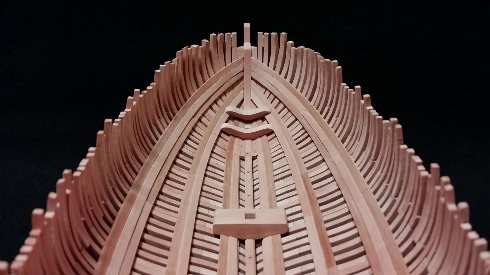
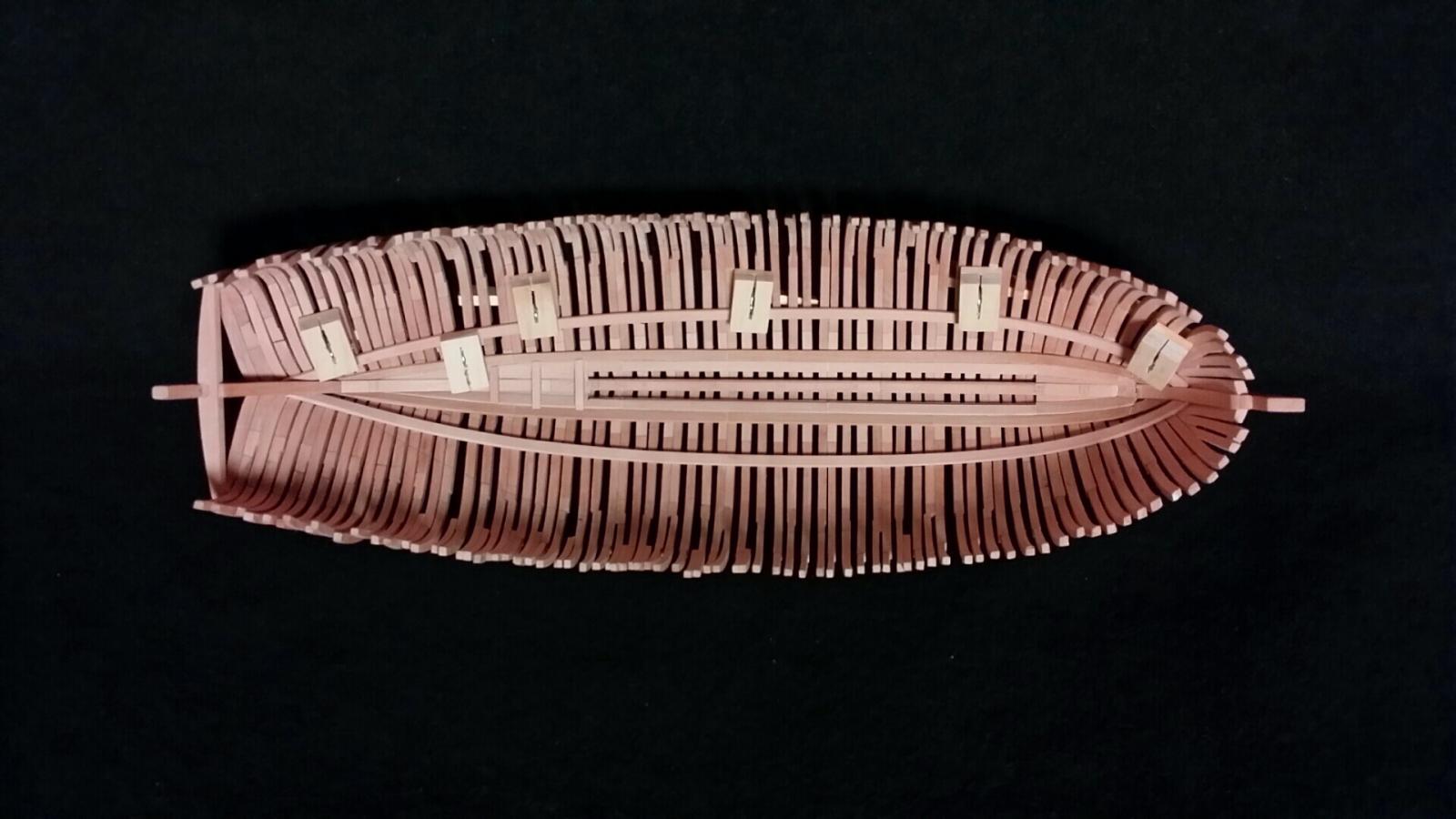
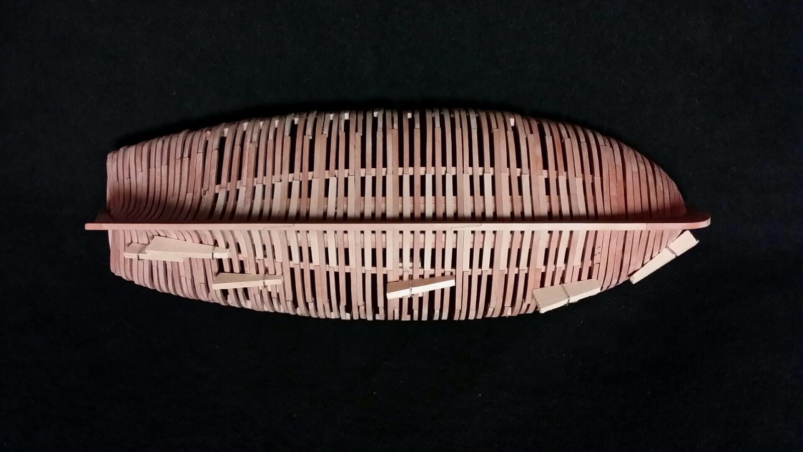
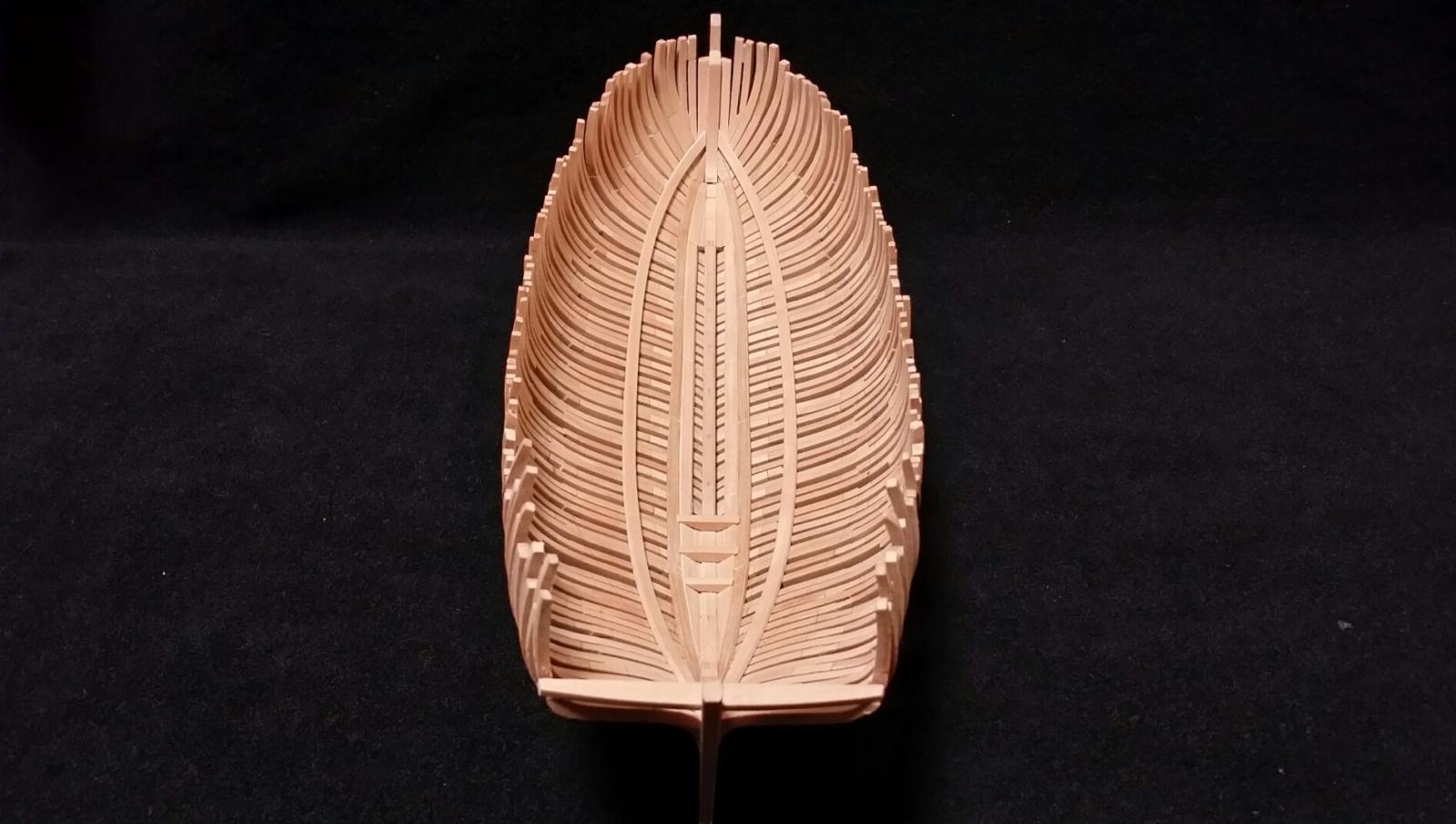
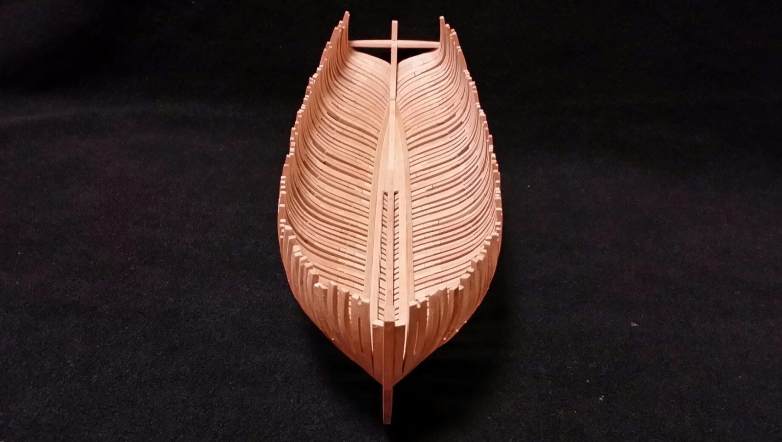
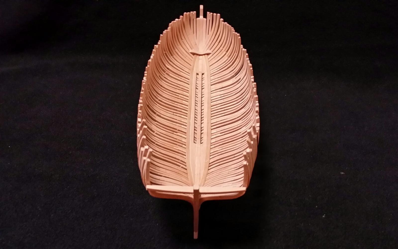
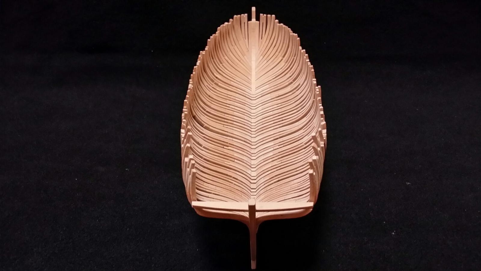
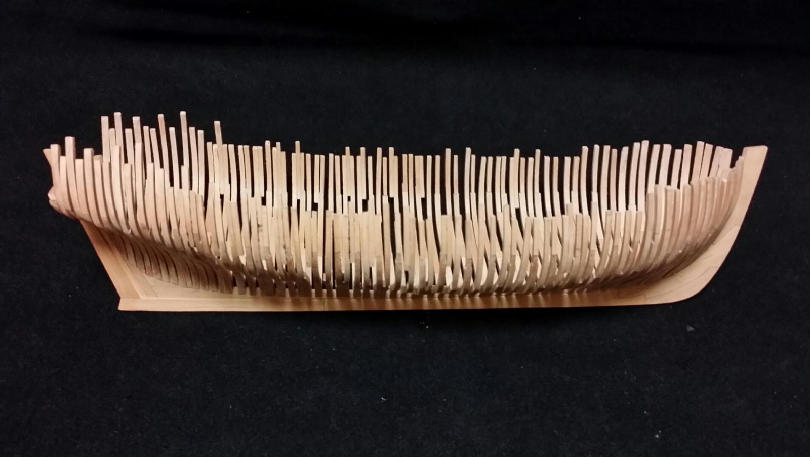
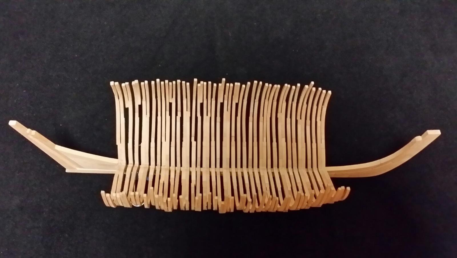
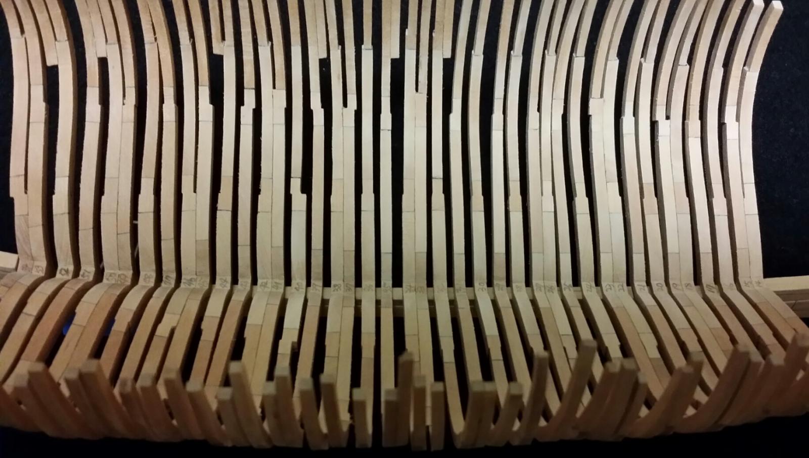
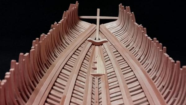
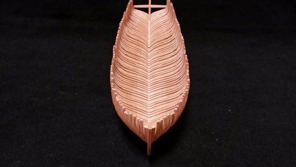
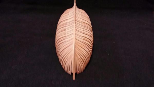
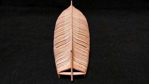
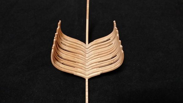
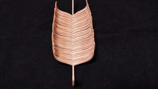
Finishing frame structure I've finished joining all the frames including fashion piece and wing transom. Counter timbers and other transom structures will be added later. As was done at fore cant frames, aft cant frames also glued to the deadwood directly without paring out the deadwood. Bearding line, the locus of cant frame feet on deadwood, was estimated with the help of Christian's plan. Below the bearding line, deadwood was tapered to the rabbet of the keel and stern. Though, the shape and spacing of frames are not well ordered, it began to seem like a boat, at least.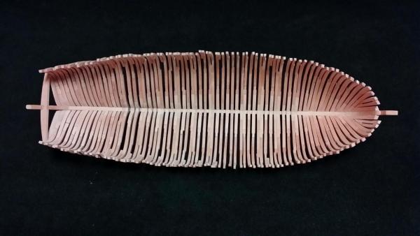

-
HMS Alert 1777 by Jaekon Lee - 1/64
Jaekon Lee replied to Jaekon Lee's topic in - Build logs for subjects built 1751 - 1800
So generous and kind, Antony. Thank you all for visiting this log and leave likes. -
Hi, Chuck. What a beautiful cutter you are building! Recently, I started building 'Naval Cutter Alert' and, with your log, I found it is almost same ship to Cheerful. So, your building log is quite helpful to me. Thanks. Lee
- 1,051 replies
-
- 1
-

-
- cheerful
- Syren Ship Model Company
- (and 1 more)
-
HMS Alert 1777 by Jaekon Lee - 1/64
Jaekon Lee replied to Jaekon Lee's topic in - Build logs for subjects built 1751 - 1800
Thank you David for your kind words. I also hope l can prepare small woodworking workshop soooon. -
HMS Alert 1777 by Jaekon Lee - 1/64
Jaekon Lee replied to Jaekon Lee's topic in - Build logs for subjects built 1751 - 1800
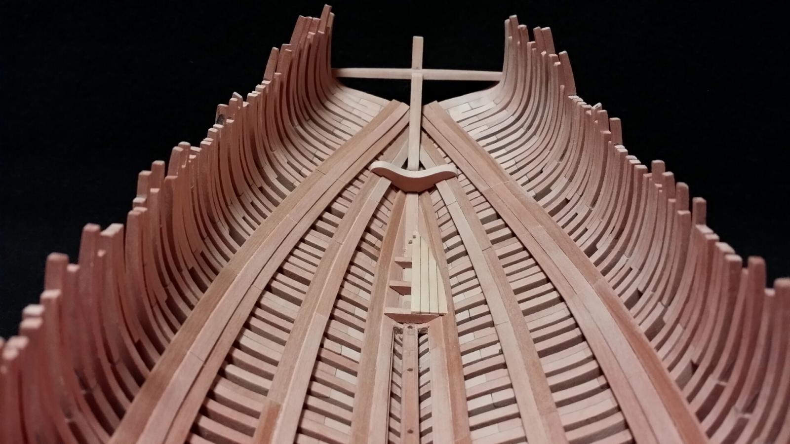
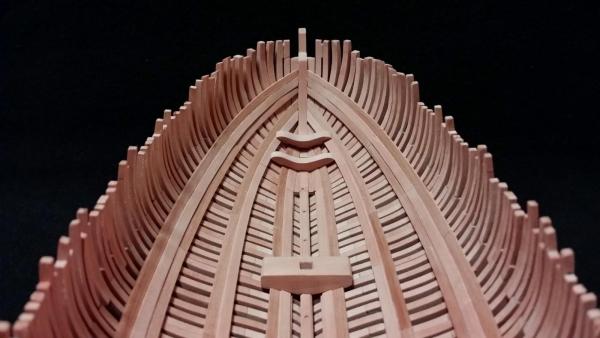
Forward cant frame and hawse pieces. After all the square frames were joined with glue to the keel assembly, forward cant half frames and hawse pieces were glued. It was also not clear, there is no sign of scoring or mortising on the apron at the plan of Goodwin, I glued cant frames directly on the forward apron. The feet of them were matched to just above the rabbet line. Now, I'm going to aft.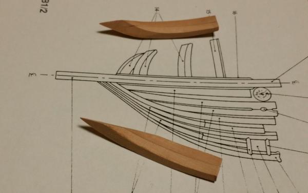
-
HMS Alert 1777 by Jaekon Lee - 1/64
Jaekon Lee replied to Jaekon Lee's topic in - Build logs for subjects built 1751 - 1800
Thanks Christian, I'm so happy to hear you. Let's see how she will grow up. -
HMS Alert 1777 by Jaekon Lee - 1/64
Jaekon Lee replied to Jaekon Lee's topic in - Build logs for subjects built 1751 - 1800
Thank you Christian for kind comments and sharing your thoughts. As I said, I'm not sure that Goodwin's frame design is authentic or not. In his book, he described the frame structure as a set of one double frame and two single frames is repeated but, he didn't mention anything about the shape of each frame. I'm curious how he designed this frame shape. I can find the similar frame design from the plan of HMS Pandora which was built in similar period. Anyway, I would like to follow Goodwin's book to respect his efforts. LEE -
HMS Alert 1777 by Jaekon Lee - 1/64
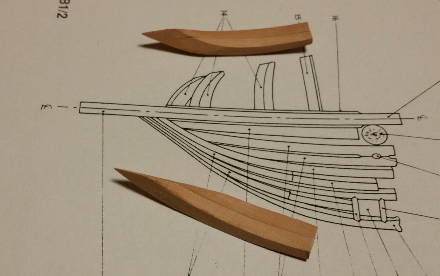
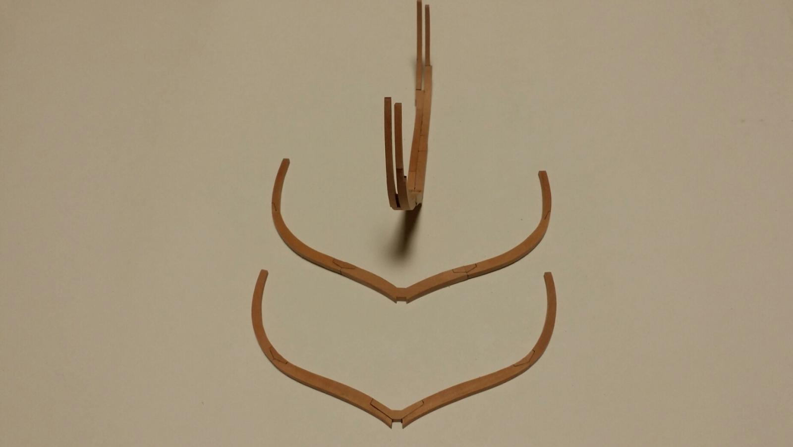
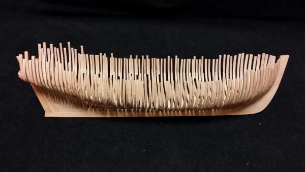
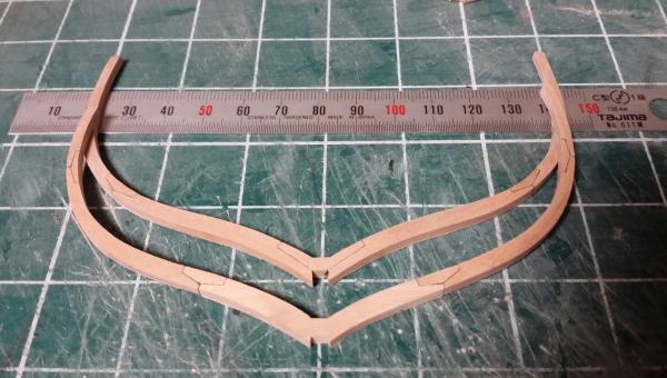
Jaekon Lee replied to Jaekon Lee's topic in - Build logs for subjects built 1751 - 1800
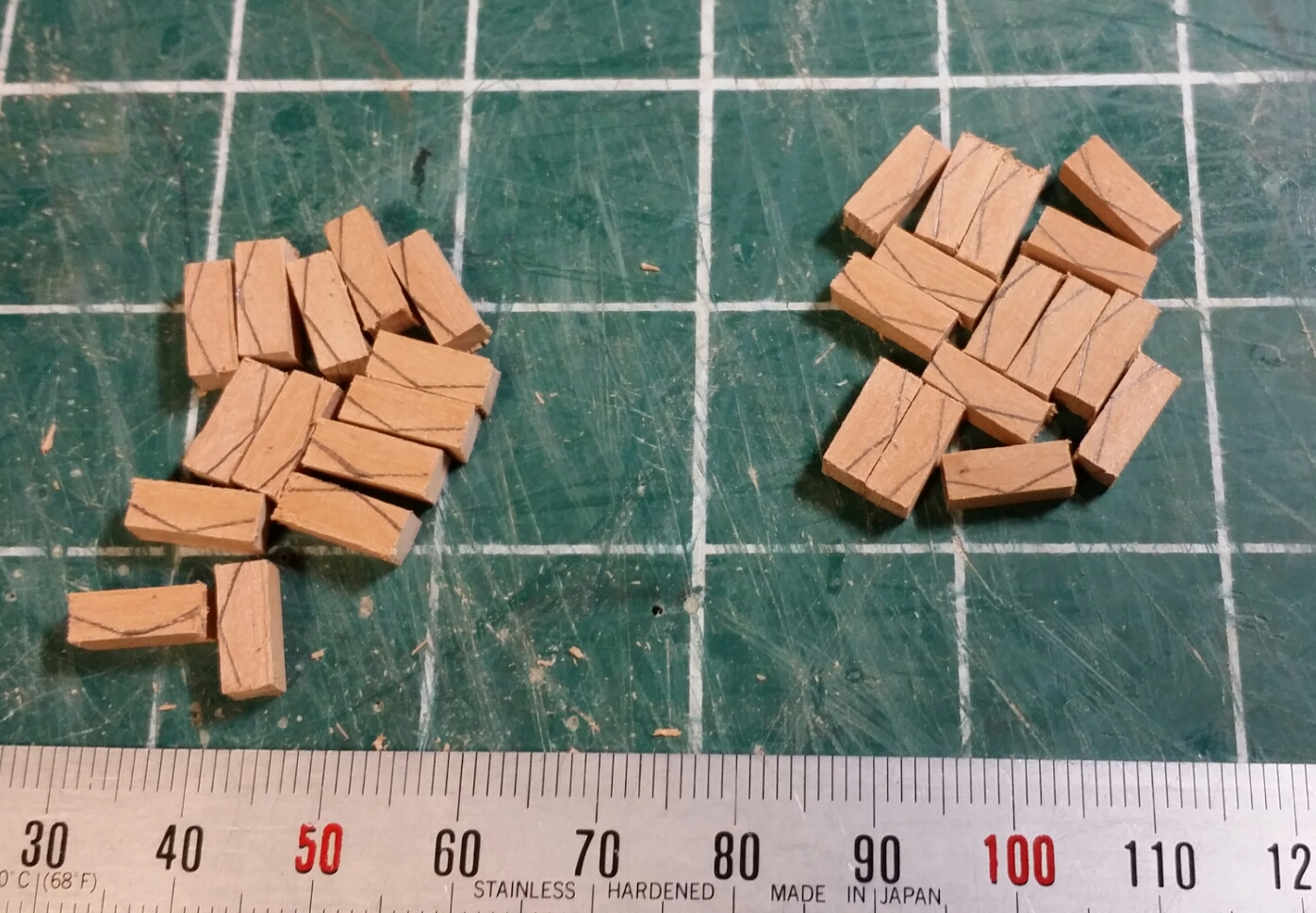
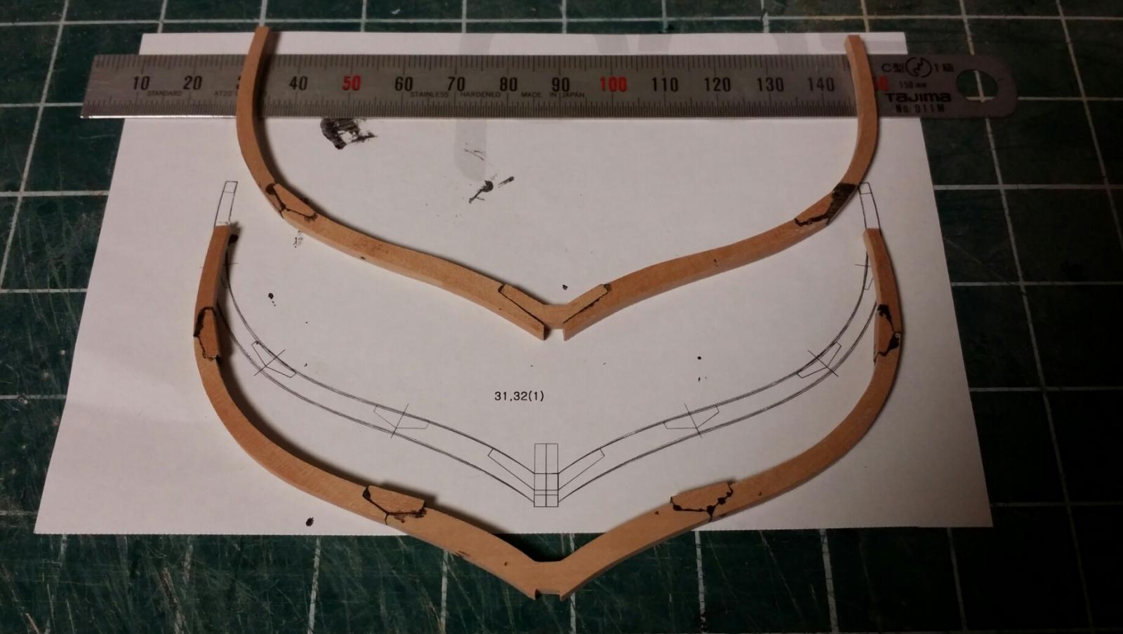
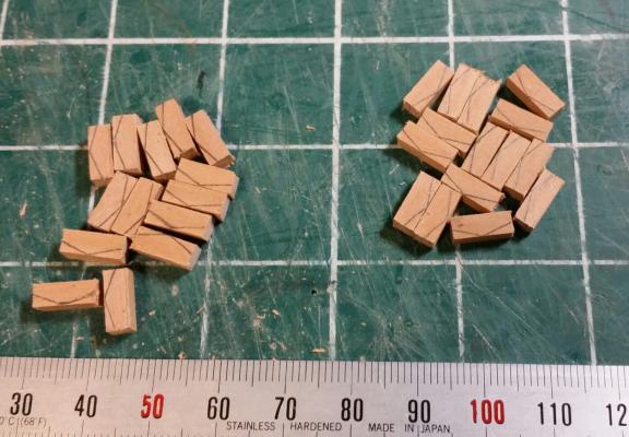
Square frames All the parts of frame were cut out from pear boards of three different thickness and glued to the square frames. After glued joints dried, all the frames were roughly trimmed and beveled to the final shape. Smoothing the inner and outer surfaces will be done after they are joined with keel. As shown on Goodwin's framing plans, most of 2nd futtocks and top timbers are shifted from lower timbers. I don't know this unique design of frame is the same as that of original ship. Though building frame of this design seems to be very tough, it is very attractive point especially for this small scale. Following pics show the progress of work. In these pics, frames are not glued yet but inserted to rising wood of the keel assembly. LEE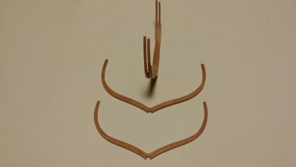


-
HMS Alert 1777 by Jaekon Lee - 1/64
Jaekon Lee replied to Jaekon Lee's topic in - Build logs for subjects built 1751 - 1800
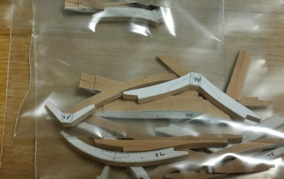
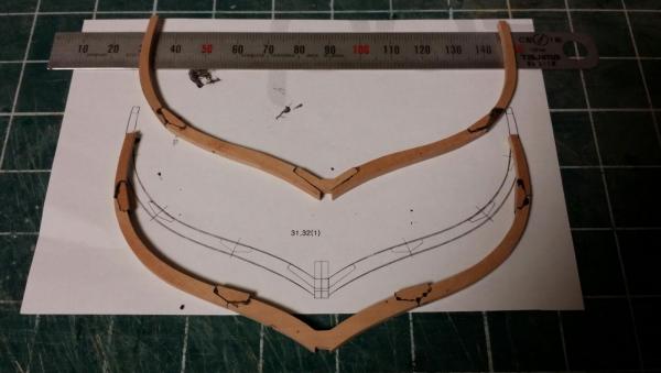
Now, I'm on the way of cutting square frame parts with the pattern of chock joint manner as Goodwin's drawing. All the frame shape is extracted from his body, half breadth and sheer plans. Time to time, imaginations were required at the ambiguous points because his drawings do not contain all the information. Anyway, I'm enjoying woodworking rather than paper working. Look at some pics about my messy table.

-
HMS Alert 1777 by Jaekon Lee - 1/64
Jaekon Lee replied to Jaekon Lee's topic in - Build logs for subjects built 1751 - 1800
Soooo kind of you, Christian. I sent PM Many thanks Daniel and Learner. I feel I got a seat at this nice forum. Lee -
HMS Alert 1777 by Jaekon Lee - 1/64
Jaekon Lee replied to Jaekon Lee's topic in - Build logs for subjects built 1751 - 1800
Thank you Christian and Pat for kind words. Christian, of course, I already found your excellent posts about Alert and read them several times. About the aft bearding line, I'm just guessing you draw it from the intersection of surfaces of deadwood and cant frames with the aid of CAD. Unfortunately, because I am so old fashioned person, I am not able to use CAD or other digital tools. So, your drawing would be very helpful for my hand drawing of bearding line and feet of cant frames.