Rick01
-
Posts
652 -
Joined
-
Last visited
Content Type
Profiles
Forums
Gallery
Events
Everything posted by Rick01
-
If my memory serves me correctly, the bowsprit/bulwarks problem is due to the bad instructions. The supplied bulwarks have a front and back, with the back being slightly higher than the front. This however is not noted on the instructions, so, like me you've probably fitted the bulwarks on back-to-front! You will also find another problem in that the three holes on the stem will be fouled by the bowsprit unless you really play with the whole setup at that point. I seem to remember that I had to adjust both the cut-out that the bowsprit sat in and the support that it rests on. Which-ever way you go the forestay holes will be a problem by the look of the clearance you have on the stem (I had a row with the maker of the kit over this). Rick
- 241 replies
-
- 1
-

-
- mermaid
- modellers shipyard
- (and 1 more)
-
With the rigging, run the rope through the pin rails from below and then just push the belaying pin through the hole securing the rigging. This way once you've completed all running rigging any tension adjustments can be made. Once happy all you need to do is make up separate coils to look like excess rigging hooked over the top of the belaying pins (hopefully you can understand this 😉 ). Rick
- 241 replies
-
- 2
-
-
- mermaid
- modellers shipyard
- (and 1 more)
-
Well we survived the last couple of years pretty well, and as you'll see from my signature I've a couple more kits under my belt (plus a couple that I didn't illustrate here). This is still probably my favourite build and from time to time I'm tempted to get it again as I feel I could do a much better job this time round. I'm keeping on following your build but I've only got around another 25 years before I start pushing up daisies, so I'm expecting you to do the right thing and finish within that time span. 😉 Rick
- 241 replies
-
- 2
-
-
- mermaid
- modellers shipyard
- (and 1 more)
-
Good to see you back on this project, remember King doesn't seem to show a bell anywhere and also (as I recall) no sign of bilge pumps. I was advised when I built this that some small cutters had dismountable pumps. Rick
- 241 replies
-
- 1
-
-
- mermaid
- modellers shipyard
- (and 1 more)
-
I always feel that the option of a clear Perspex side should be available, just to display the intricate work that goes on inside the model. Check this out https://www.arcair.com/Fea1/201-300/Fea206a-Wellington-Hill/00.shtm Rick
-
Thanks for the link Andy - I already know at least one of the stories "Winston Parker". I'm deeply involved with a FB page about Stalag VIIIB Lamsdorf where he was held and am helping set up a web page covering all allied POW's held in Europe during WWII. Rick
-
On top of the discomfort all you can see from the seat is a part of the instrument panel! I stood slightly back from that position in the Walk Through frame just to get an idea of what my father had experienced - all I can say is "Not Nice". Rick
-
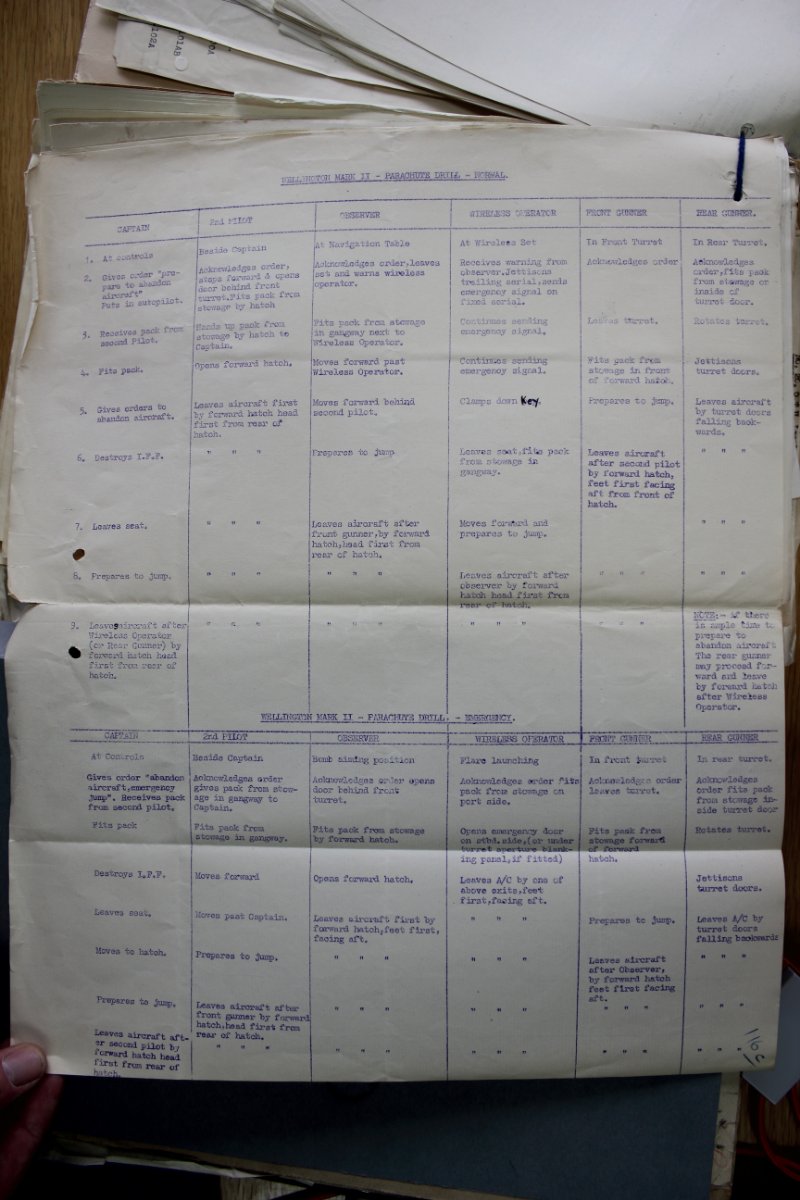
I don't know if you've been supplied with parachute packs, but if so, here's the positions and order of bailout from a Mk II (unchanged I guess from the Mk I. . All very well - unless your bomb aimer manages to pull his ripcord whilst still in the nose! Wireless operator and front gunner bundled him up and threw him out. He ended up with a strained groin,treated by a local Dr and passed back to England by the underground. The rest of the crew spent the rest of the war as POW's. Rick

-
It's a "walk through" display at Brooklands Museum alongside R-Robert. Basically just a fuselage using assorted items collected over the years, but it really does make you appreciate what the crew went through every time they flew. Rick
-
This is the bit in real life. 🙂 Note the cut-out in the seat for the control column (useful when pulling back hard to get an enemy fighter off your tail ). Rick
.thumb.JPG.9c5bc6c6f76945745c5414593a28d527.JPG)
- 174 replies
-
- 11
-
-
No argument - the one on the right. I've seen R-Roger in the UK and the colour was very close to the right one (as was the earth colour you have shown). Rick
-
Thanks Andy - I have seen it but my skills are just not good enough to do it justice I'm afraid. These are two of the exits when told to bail out. This one is a kick out panel on the side of the aircraft (just below the roundel position). It would have been a bitch to get throufh when wearing full flying gear plus parachute. ... and this was also kick out after lifting the duck boards, although not all the Mk I/II series had the blank for a belly gun position. This shot does give a fair representation of the colour of the framing. Rick
.thumb.JPG.4d397c31f25d7afbfb60851e513e1030.JPG)
.thumb.JPG.20f69f145f54ebde3acc37385eefa36f.JPG)
-
I can also add a direct interest in the build. My father was 2nd pilot in a Mk II , shot down over le Havre on his second time out and spent the rest of the war in Stalag VIIIB. Rick
-
Did that at the same time as posting these photos. 😉 Thanks for following, I wonder, if I'd put a couple cannon on it and built it as an 18th century dhow, would it have gained a little more attention? I do have another couple of builds under my belt, but they didn't make it here, now to decide what next. Rick
- 35 replies
-
- 1
-
-
- Artesania Latina
- Sultan
- (and 1 more)
-
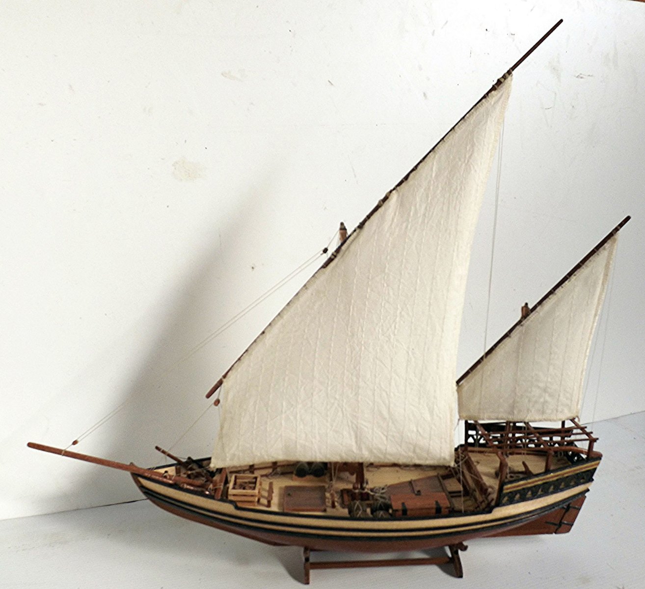
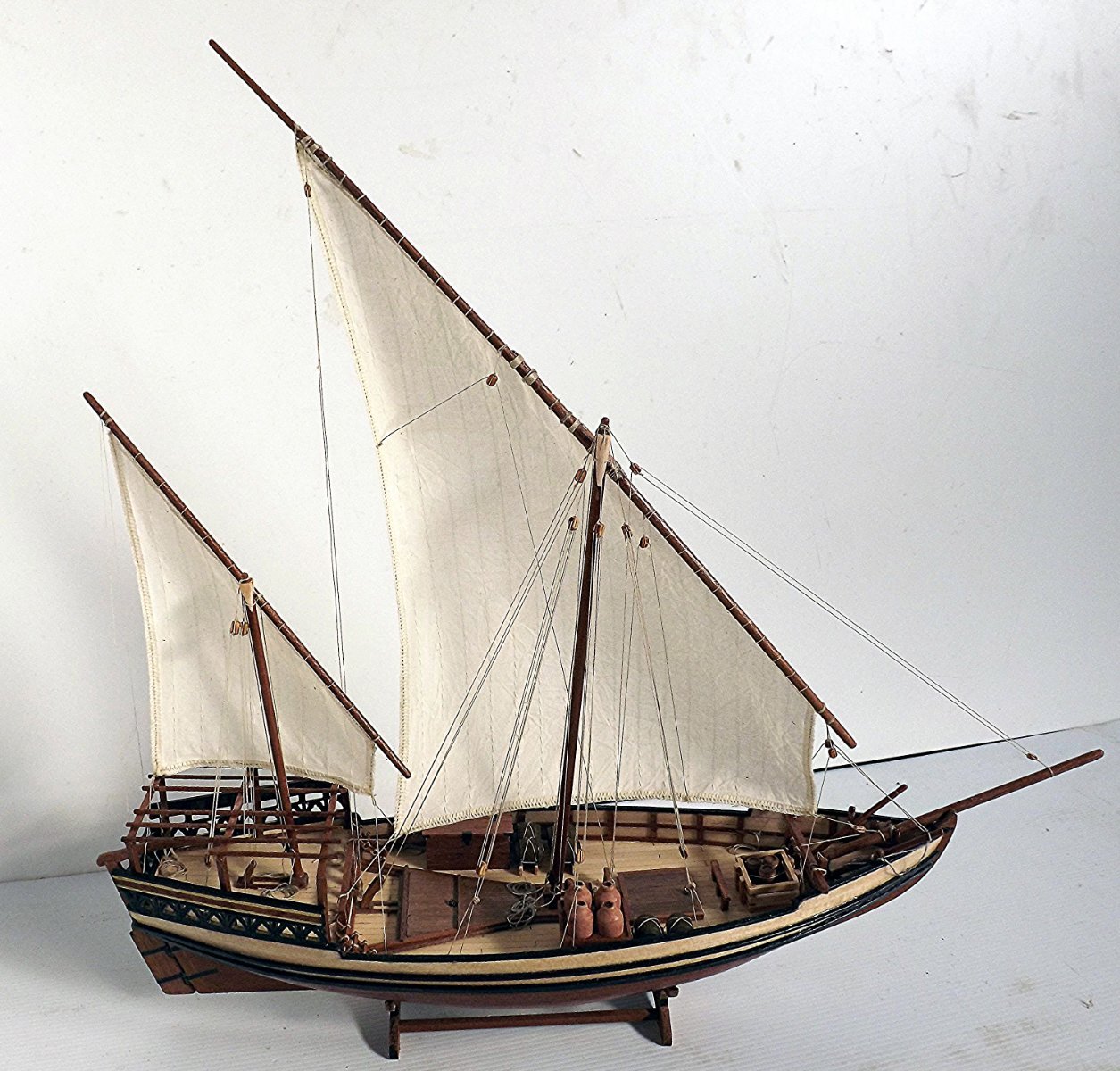
Finally finished. For anyone else attempting this model I'd strongly recommend a good magnifying glass to read the instructions and study the pictures. A lot of research on what these vessels actually look like, including the rigging. Measuring and dry fitting items at every step. Before gluing anything check ahead in case you find that fixing the item may interfere with later actions i.e. deck furnishings. Other than that - enjoy. Rick


- 35 replies
-
- 13
-
-

-

-
- Artesania Latina
- Sultan
- (and 1 more)
-
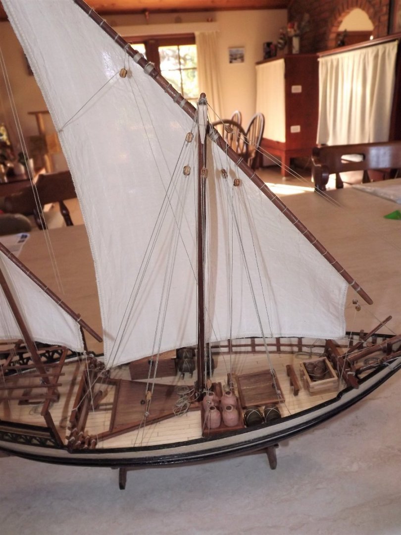
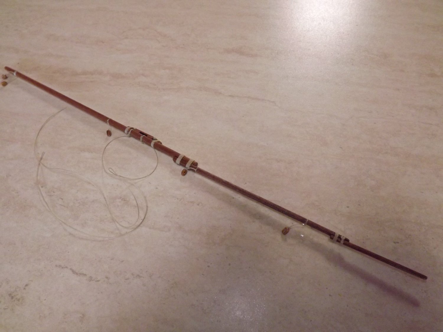
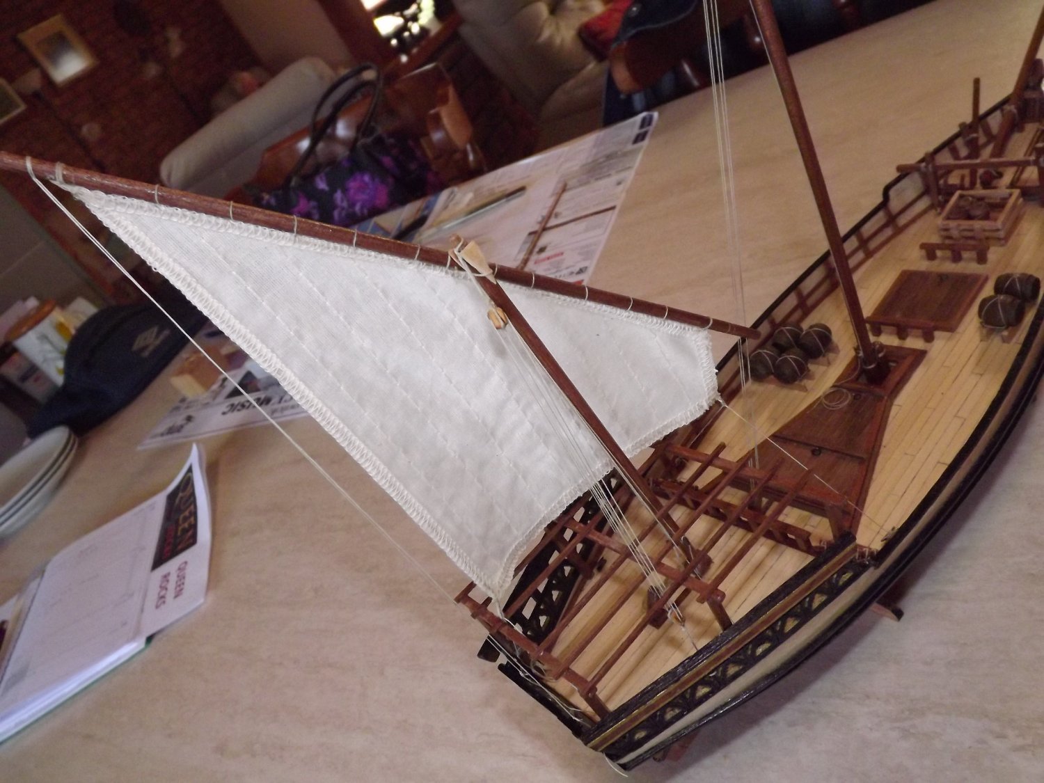
First assemble, then dress the yard. According to the instructions it's assemble,sew on the sail, then mount the yard.After that then add various blocks once the yard has been hoist. Much easier however if you fully assemble all items that are attached to the yard before hoisting it. It was then just a matter of sewing on the sail, hoisting the yard and then commencing the rigging. I I re-arranged the siting of the sea chest and amphora so as to not interfere with any rigging and the mast stays are only mounted on the starboard side of the ship (see my previous post). I also re-sited a some of the bow rigging in order to effect a free flow of the cables and a more effective control of the sail. A couple of shots of the finished item will follow. Rick


- 35 replies
-
- 5
-
-
- Artesania Latina
- Sultan
- (and 1 more)
-
Finally pinned down a couple of illustrations of dhows to help with rigging the main mast/sail. This is a short description of an Indian two-masted "dhow" measuring 40 ft (the kit measures 70 ft along the deck) https://journals.openedition.org/archaeonautica/594?lang=en . This is a 60 ft modern dhow clearly showing the rigging to the main mast https://www.eastafricayachtcharters.com/60ft-zanzibar-charter-boat-dhow . In both variations it's pretty clear that there are no stays on the "sail" side of the mast. I've also seem a few photos of working decks but no good close-ups, these seem to show that they are pretty untidy including ropes piled rather than neatly coiled/hung from gunwales. I'm working on the main mast and spar and should have something further to post shortly. Rick
- 35 replies
-
- 1
-
-
- Artesania Latina
- Sultan
- (and 1 more)
-
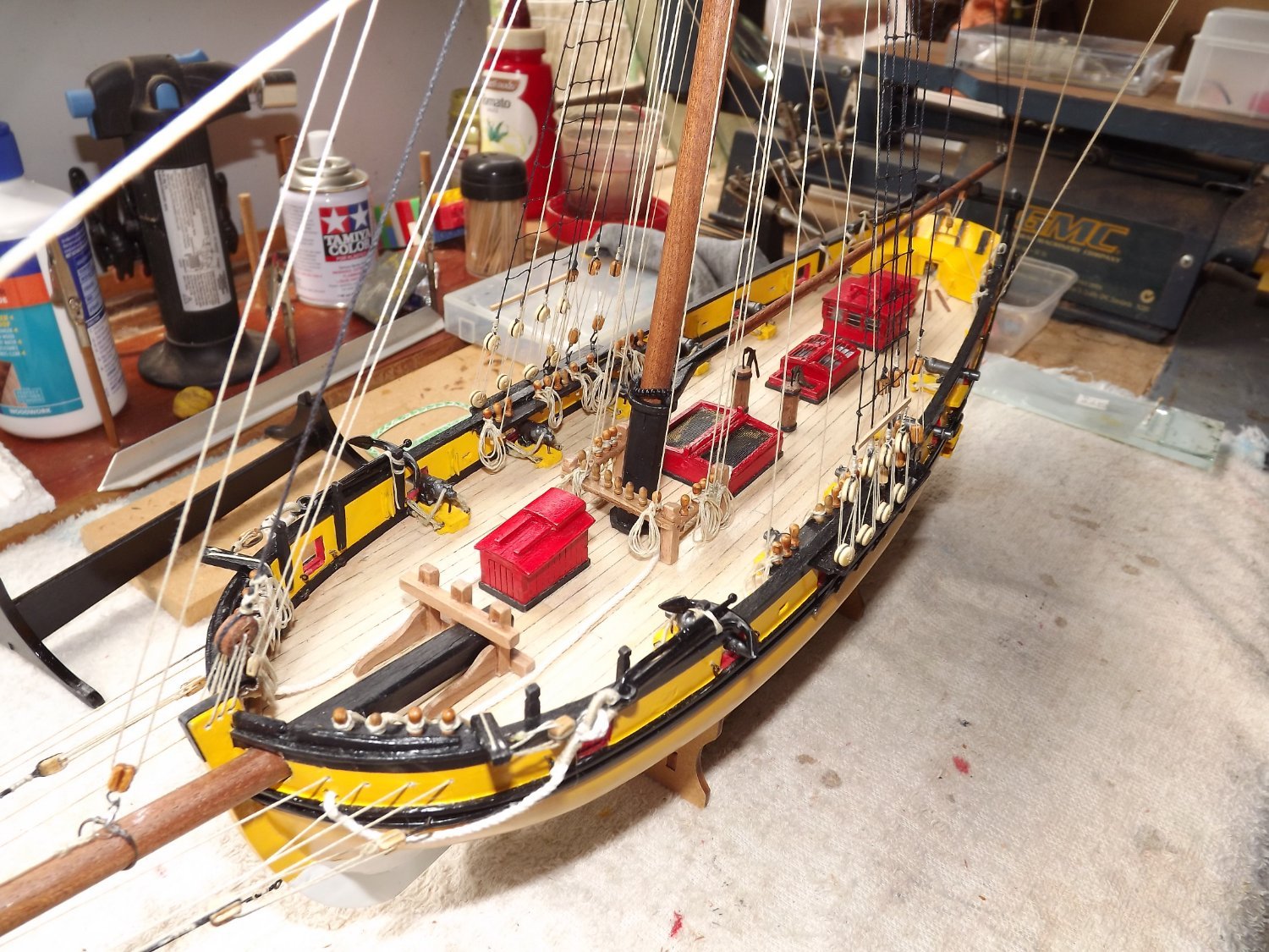
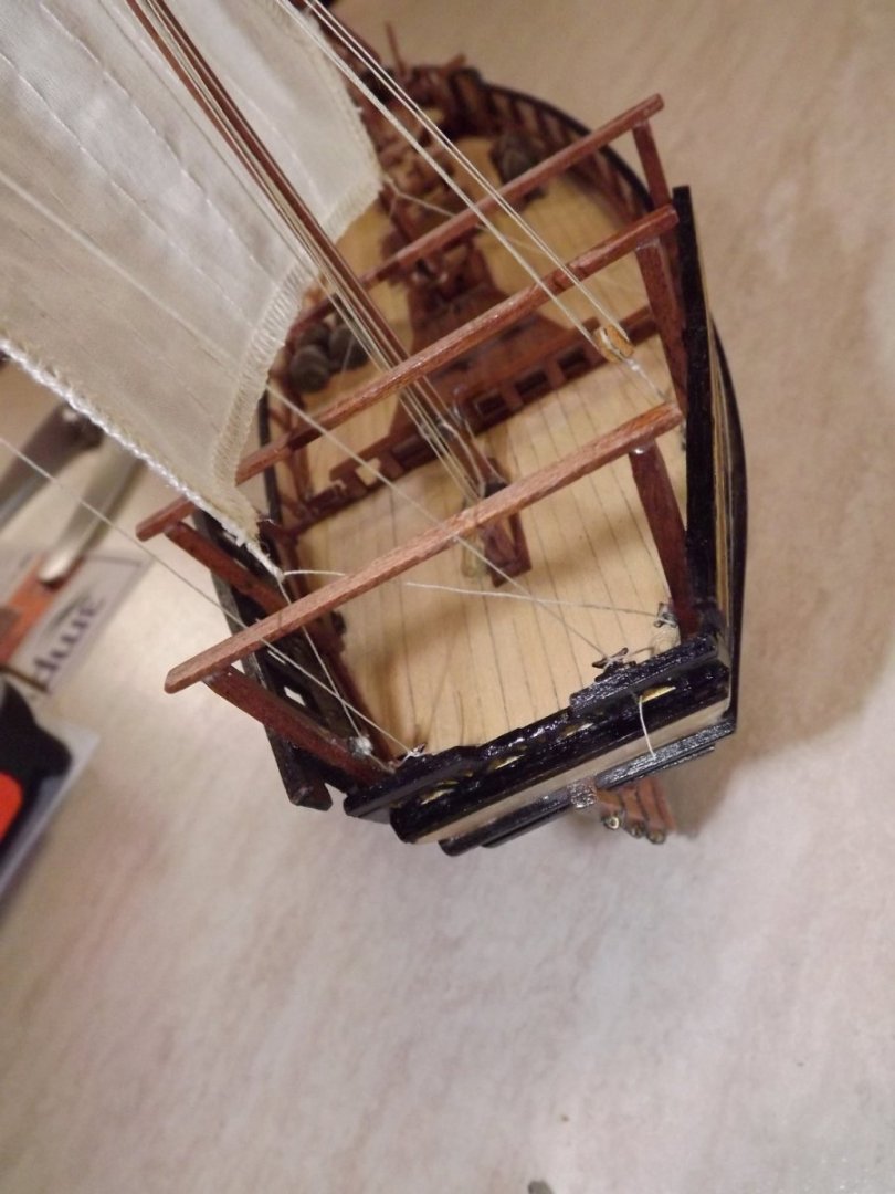
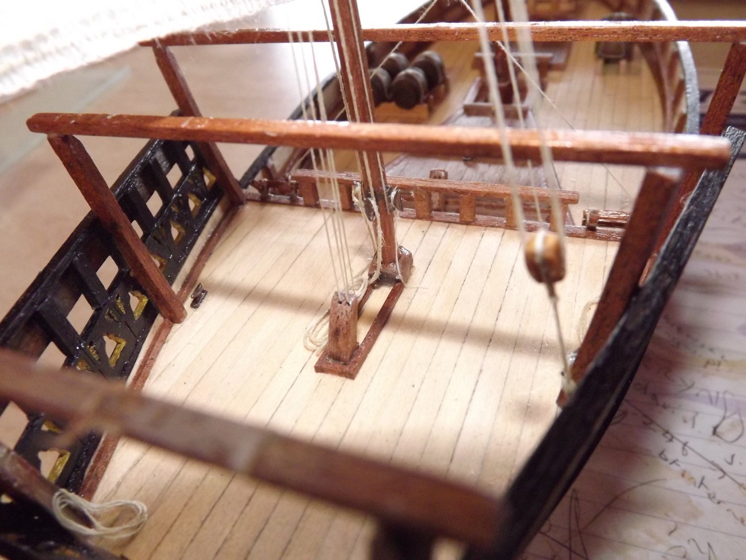
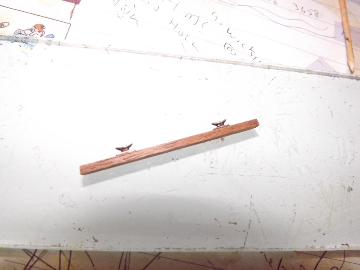
Well after considerable searching on the net the only half way constructive advice I could find was this nice item here. It seems that the jury is out on a number of items concerning rigging this type of sail and thus I'm working on what (to me) seems common sense. First I stripped back the cover supports as they were fouling any run that I attempted for control of the sail foot and spar tip. I then added two more cleats to the mast, this way the sail hoist, a second rope used to hold the spar against the mast, plus the rope which tensions the mast brace, all have a separate securing point. In the foreground is a further brace for the mast, on the opposite side to the sail. There will not be one on the other side. Next I built a strengthener with cleats for the top of the fancy work on the counter. This was added as two sections to allow the rudder bar free play. Despite appearances the cleats are inboard, not on top of the reinforcing strips. The end result has allowed me to rig the lines controlling the sail foot and spar tip to be added, without (again) using one cleat for two lines and without rubbing on any woodwork. The end result isn't too bad and once I've dealt with the sail to give it the impression of wind filling it, all the lines should run freely. I know the sail is pretty average but it's past my ability to construct a better one, arthritis in my fingers is severely hampering my dexterity. Rick


- 35 replies
-
- 2
-
-
- Artesania Latina
- Sultan
- (and 1 more)
-
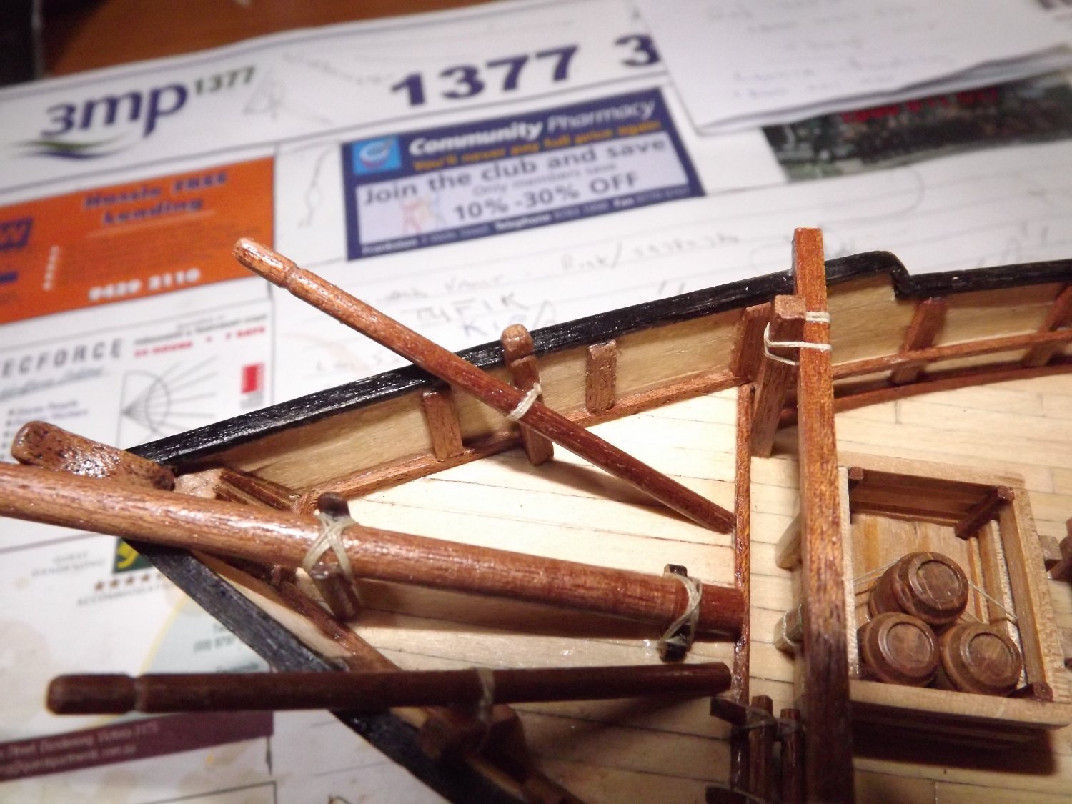
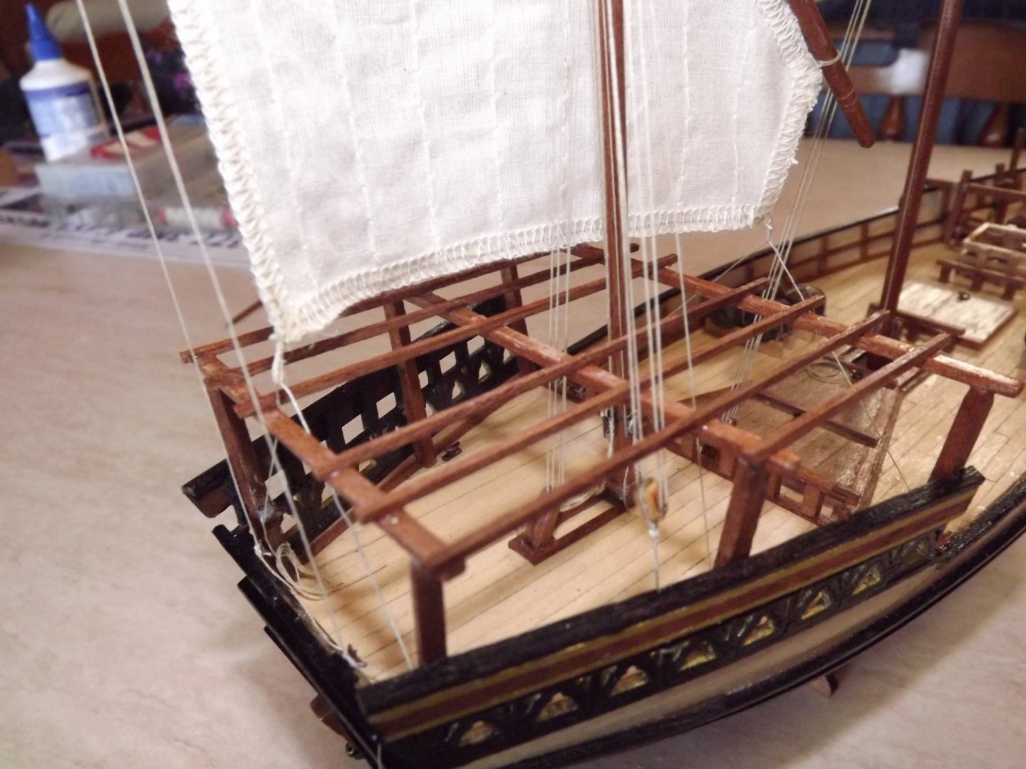
Things are now about to come to a screaming halt! Again I've amended the build slightly, the "shade" area at the stern now consists of a number of flat slats, not the convex cover shown in the plans. 99.9% of the actual dhow photos that I've seen use the slats and only a very few use a tent like structure and these latter seen to be tourist boats. Masts have also been stepped. Spars and rigging next and this is where I have major problems. As you can see, the instructions are pretty poor and illustrations as clear as mud. The bottom left illustration seems to indicate a hoist for the spar coming down to a cleat on the mast. Now check the next page. Here illustration 2 and 3 show what appears to be a brace for the mast, again terminating on the same cleat but over the spar hoist. Surely you don't release the mast brace every time you lower or raise the spar! Nest problem is the two braces (green thread) shown at 4 and 5. If these are correct then the spar is effectively working fore and aft only. The same is shown later for the main mast/spar. Again every illustration of a dhow under full sail shows the spar as working almost as a square sail. So, at this point I'm off to find some sort of dhow rigging manual to try and clarify this area. Rick
.thumb.jpg.5106ed5e6d884a0a5e96a2ae0b771b8f.jpg)
.thumb.jpg.470d233fa92f94bffff73af896af3e35.jpg)
- 35 replies
-
- 3
-
-
- Artesania Latina
- Sultan
- (and 1 more)
-
When making my coils for the belaying pins I make up a jig from scrap MDF . Standing on edge I put a number of small nails/pins in close to the edge and after making a coil of 6~8 loops, place it over a nail/pin hanging down. To shape it so that it sits somewhat realistically I then use white PVA glue and carefully pinch the coils into the required shape. make sure you do have a small space at the top so that you can use short length of line to tie the coil to the belaying pin. See the sample I posted further up this page. Rick
- 362 replies
-
- 2
-
-
- Amati
- Lady Nelson
- (and 2 more)
-
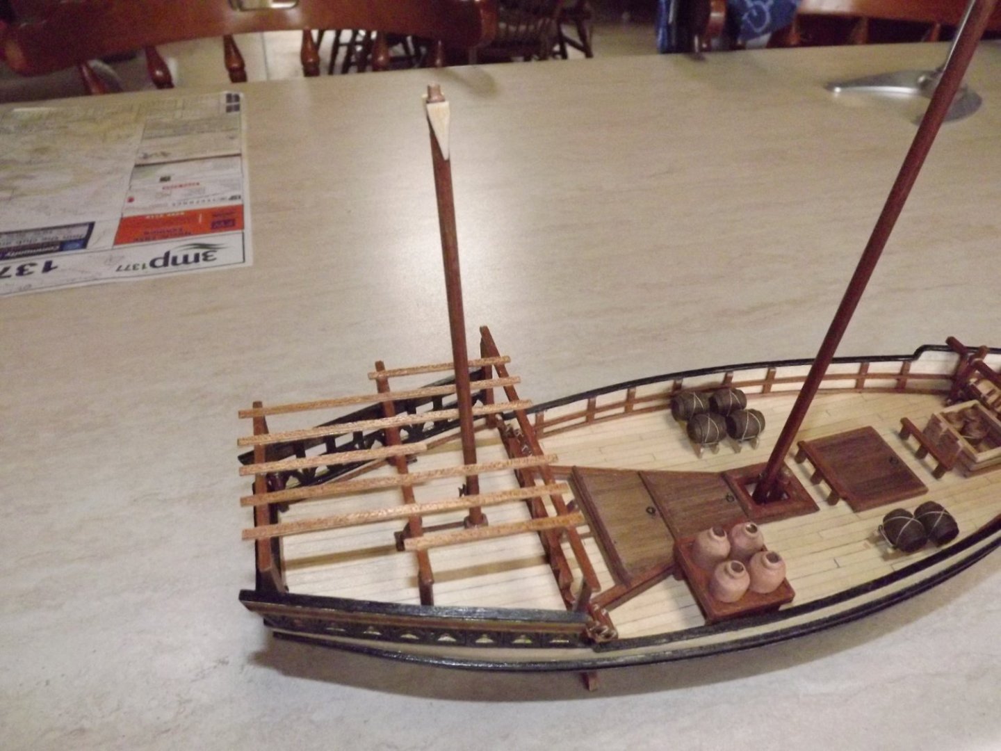
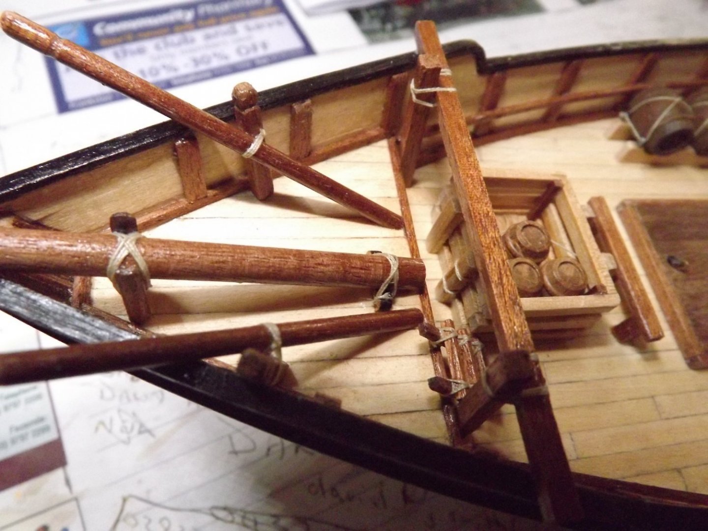
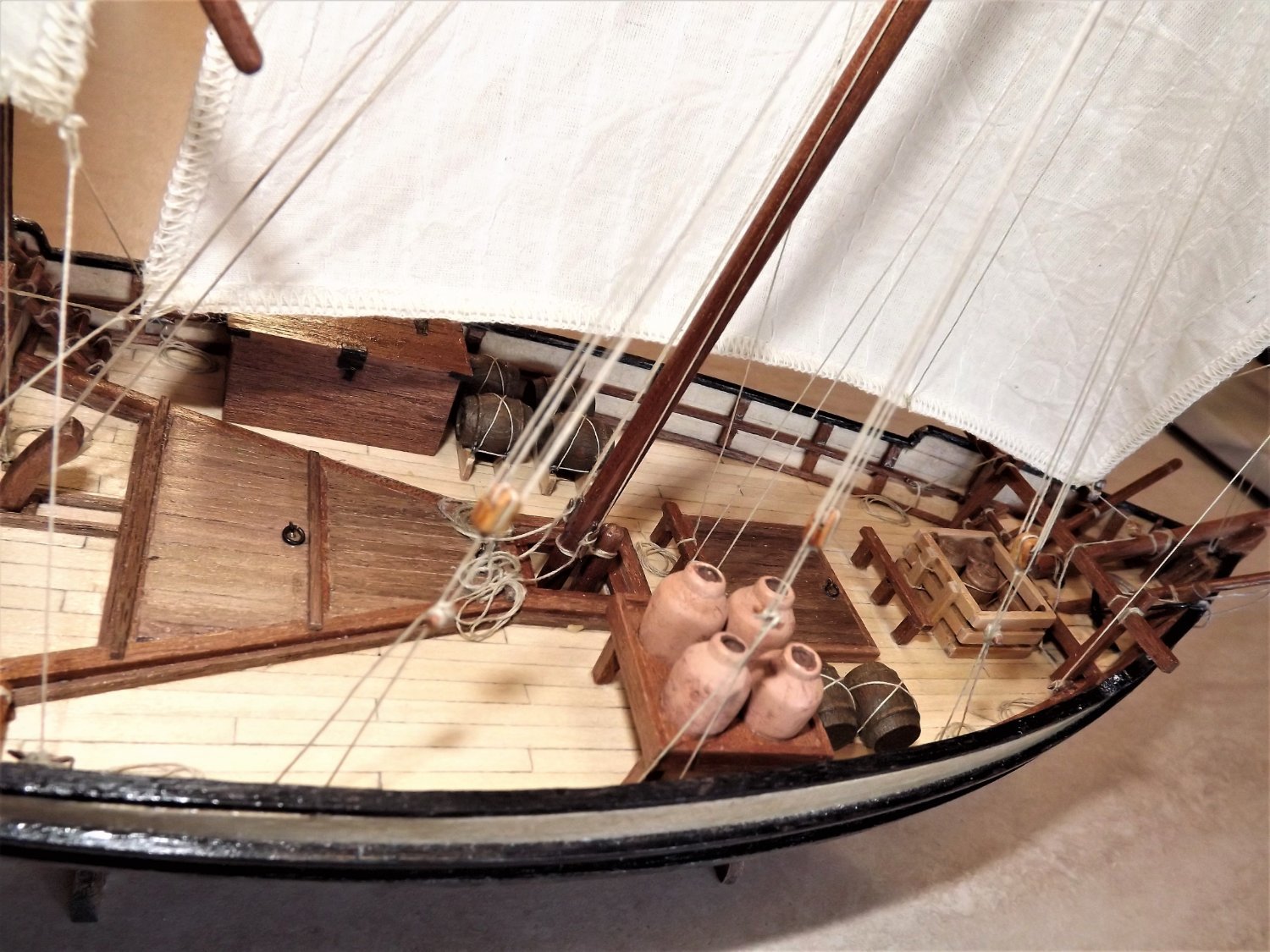
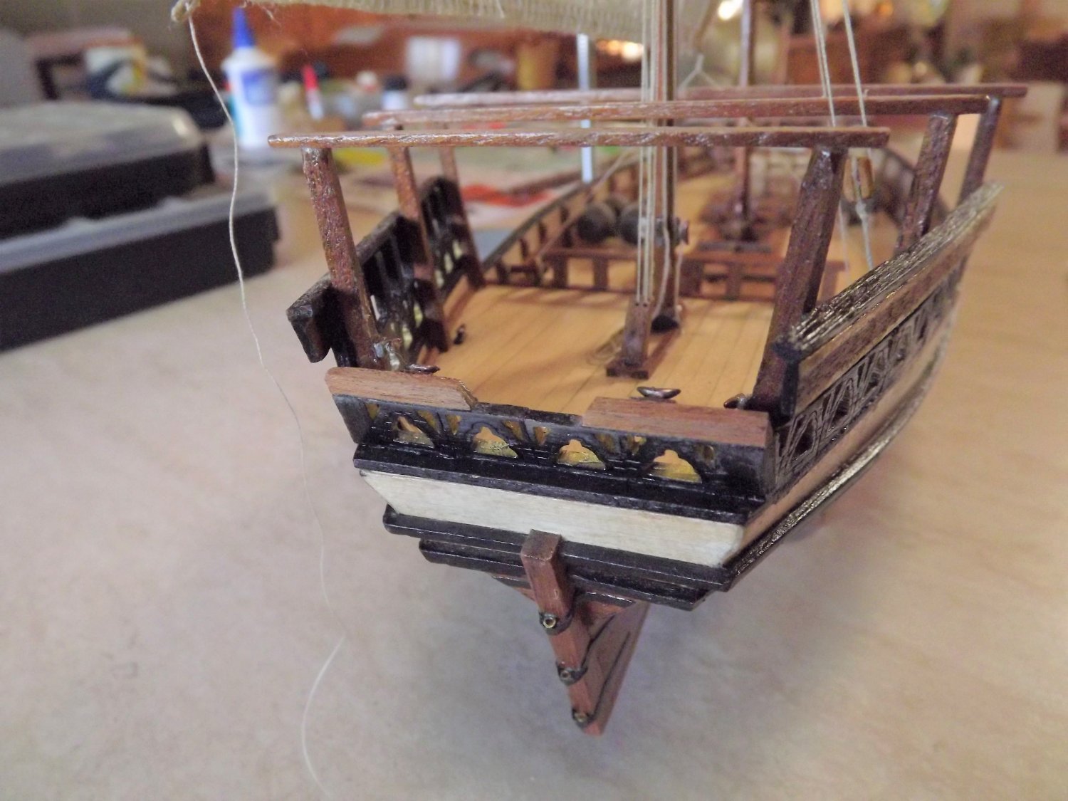
Absolutely NOT my best photo yesterday so I re-did a couple today. Here is a better couple of shots of the work on the fore deck. Rick

- 35 replies
-
- 2
-
-
- Artesania Latina
- Sultan
- (and 1 more)
-
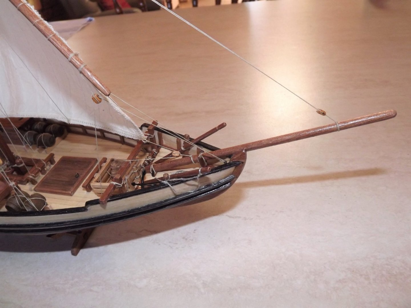
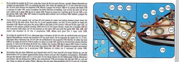
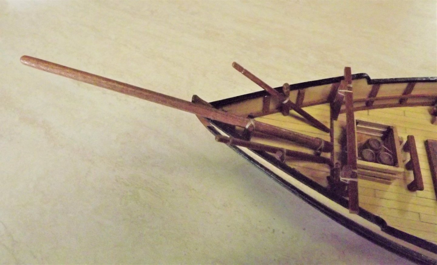
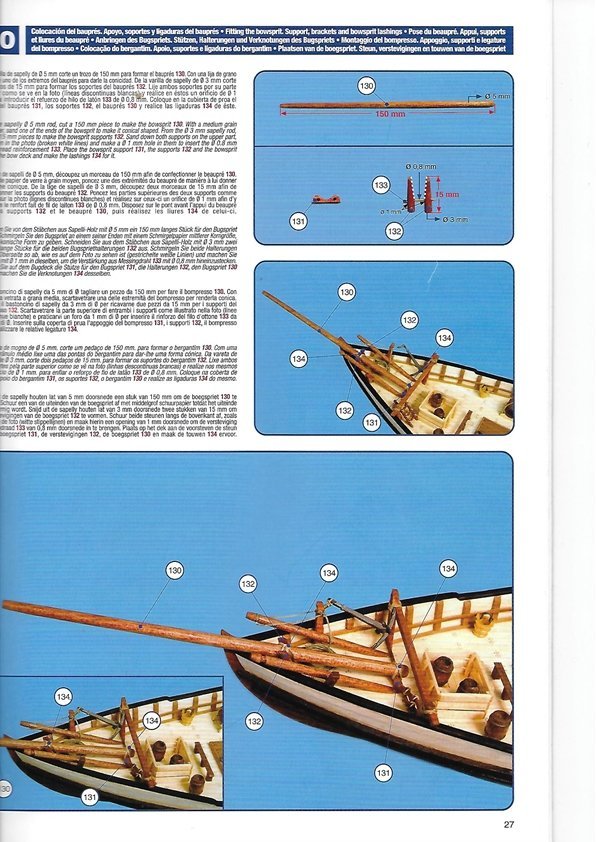
On to the fore deck fittings. First get a magnifying glass, the plans are pretty small in this area and, unless you've 20/20 eyesight they're a pain! I'll mount the anchor later as it's a poor casting and needs some attention. Looking closely, parts 117 and 118 need a slight groove for the rope to run in. Additionally I found that part 118 also needed another 2mm added as it did not project high enough over the gunwales at the recommended 18mm. I also added a lashing where the part 117 rests against part 118 although this is not shown on the plan. I did this after finding a number of photos on-line showing the deck of a working dhow where everywhere any fixture crossed another it was secured with lashings. The next step was assembly of the bowsprit. This appears to be only slightly tapered if at all and from what I could find on-line seems correct. Having cleaned and shaped parts 130 through 133, I assembled them before mounting on the deck. The instructions appear to recommend mounting to the deck then lashing - try that and you'll tie yourself in knots with the attempt! Instead of using the brass wire (133) I used a wooden spacer, less of a problem than trying to drill the 1mm holes in very splintery dowel and also more likely to have been used on the real thing. It was a little fiddly getting the parts 132 the correct length but not impossible. Rick
- 35 replies
-
- 5
-
-
- Artesania Latina
- Sultan
- (and 1 more)
-
At least make up a couple and give it a try. It just finishes off the rigging. It's basically a matter of making a coil of 6~8 loops round something like a thick pen, with 4~5 centimetres of line tucked under the loops. Tie it off to hold the loops together and use a little PVA glue to shape the rope into something resembling a natural fall. Once it's dried then, using the excess line hook it up onto the belaying pin, a little more PVA to position it and it's done. Fiddly I know but worth the effort. Different ship, but you get the idea. Rick

- 362 replies
-
- 4
-
-
-
- Amati
- Lady Nelson
- (and 2 more)
-
Are you going to add coils of rope where-ever you've ended any running rigging? Rick
- 362 replies
-
- 1
-
-
- Amati
- Lady Nelson
- (and 2 more)
-
As someone else has suggested - ground up, middle outwards and front to back. All standing rigging needs to be completed first (but after such items as booms etc), then the ratlines and finally running rigging. This is similar to actual practice, after all you re building a miniature ship. It will be a little awkward but not impossible. Rick
- 362 replies
-
- 2
-
-
- Amati
- Lady Nelson
- (and 2 more)
.JPG.23e9ec020cb659b2d3abdf5a5712745c.JPG)
.JPG.c61fab6a27ca1c7df49398a371d0bbc5.JPG)
.JPG.0359fb382ec67214948eeb3a122347ce.JPG)


.jpg.a3f5e984f168086b9d60fe9f72b70aad.jpg)
.jpg.6984430c548b2002f6658415345071a7.jpg)