Rick01
-
Posts
652 -
Joined
-
Last visited
Content Type
Profiles
Forums
Gallery
Events
Everything posted by Rick01
-
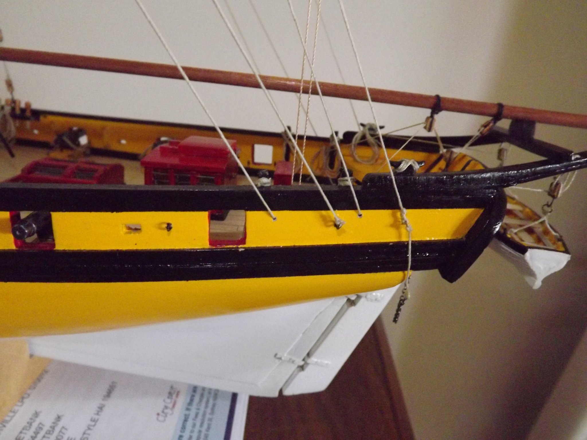
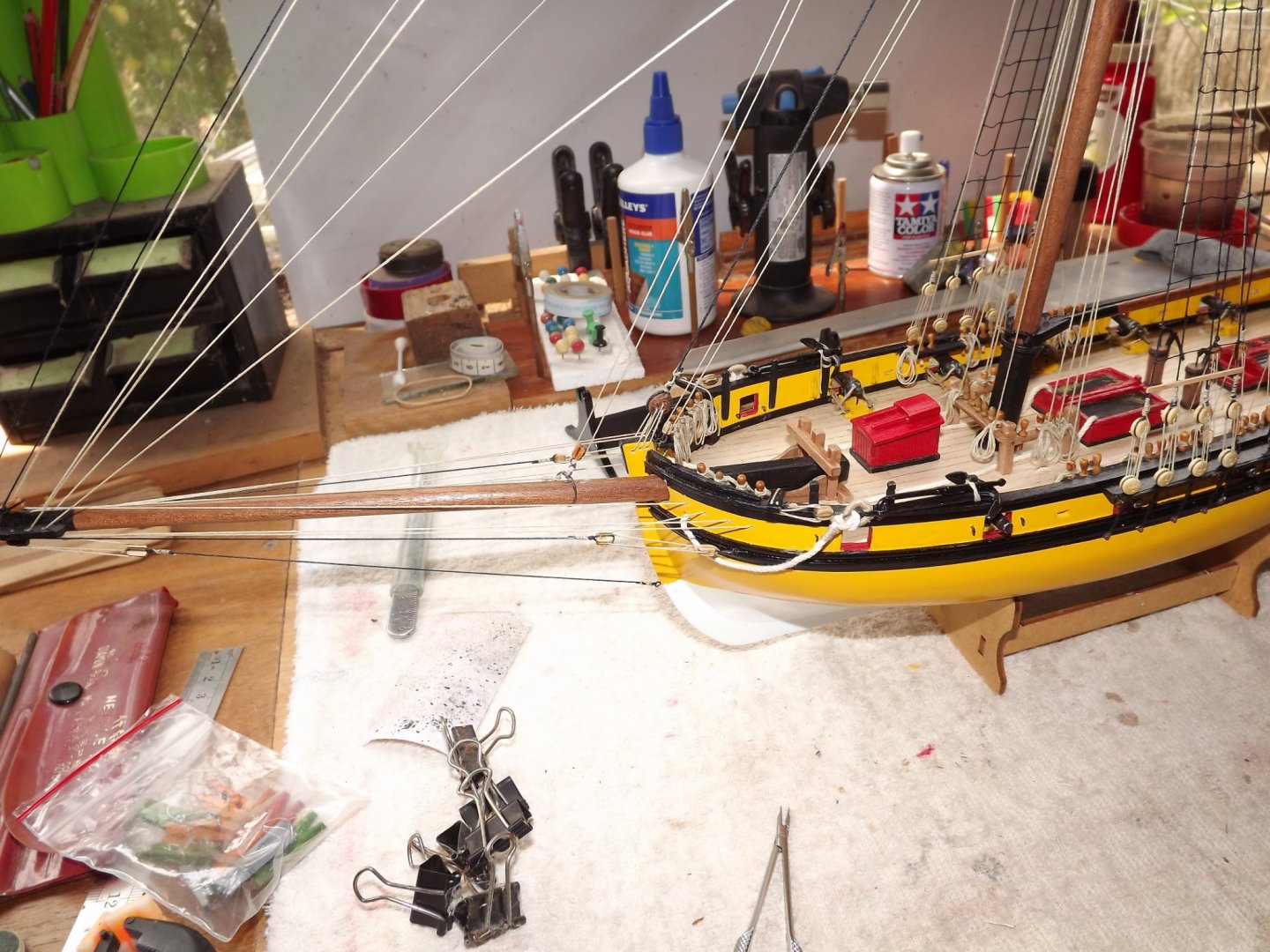
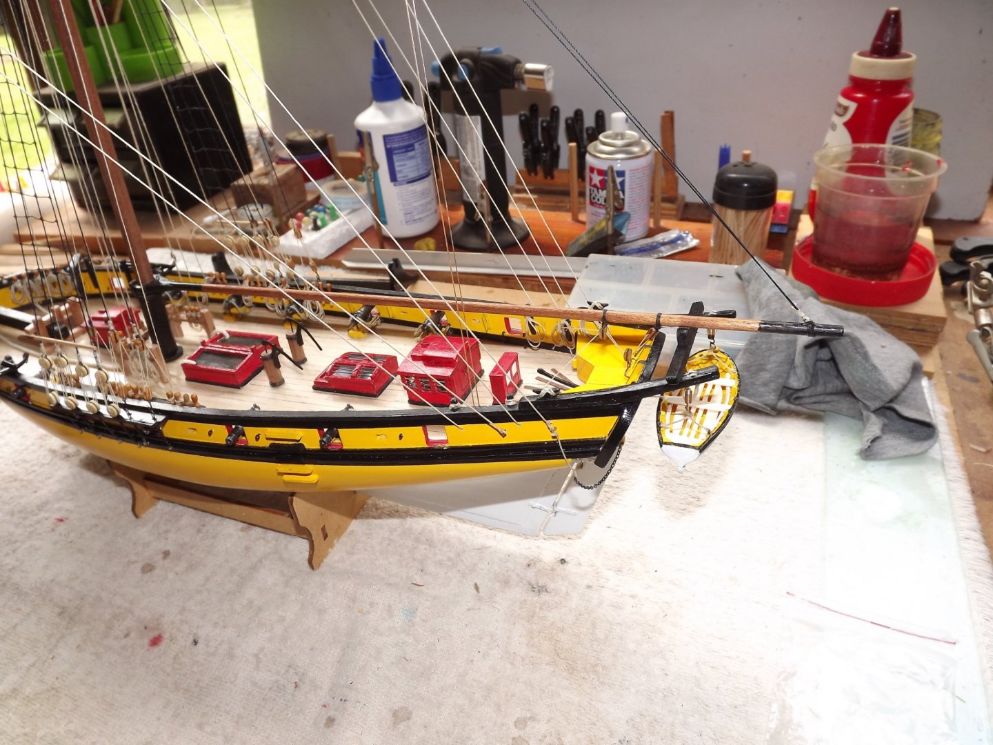
Hi Tom, One of the AL problems is less than clear instructions. In this case the "connections" are eye bolts, just above and forrard of them is a hole that the running rigging for the yard arms is passed through before attaching to the relevant knight heads. I rigged mine model with somewhat more complexity than AL show, so if you look at this photo you'll see a block at the yard arm tips. The yard brace is then run up to the block and back down, through the gunwales and then looped round the knighthead (if that's the right word). It just makes more sense to me to run the braces this way than the way AL illustrate. These two shots should make it clearer. Apologies for sort of hijacking your thread here Gafrigg 😞 Forgot the cleats - just a drop of supa glue and a prayer that I didn't become part of the attachment. Rick


- 110 replies
-
- 3
-

-
- le renard
- artesania latina
- (and 1 more)
-
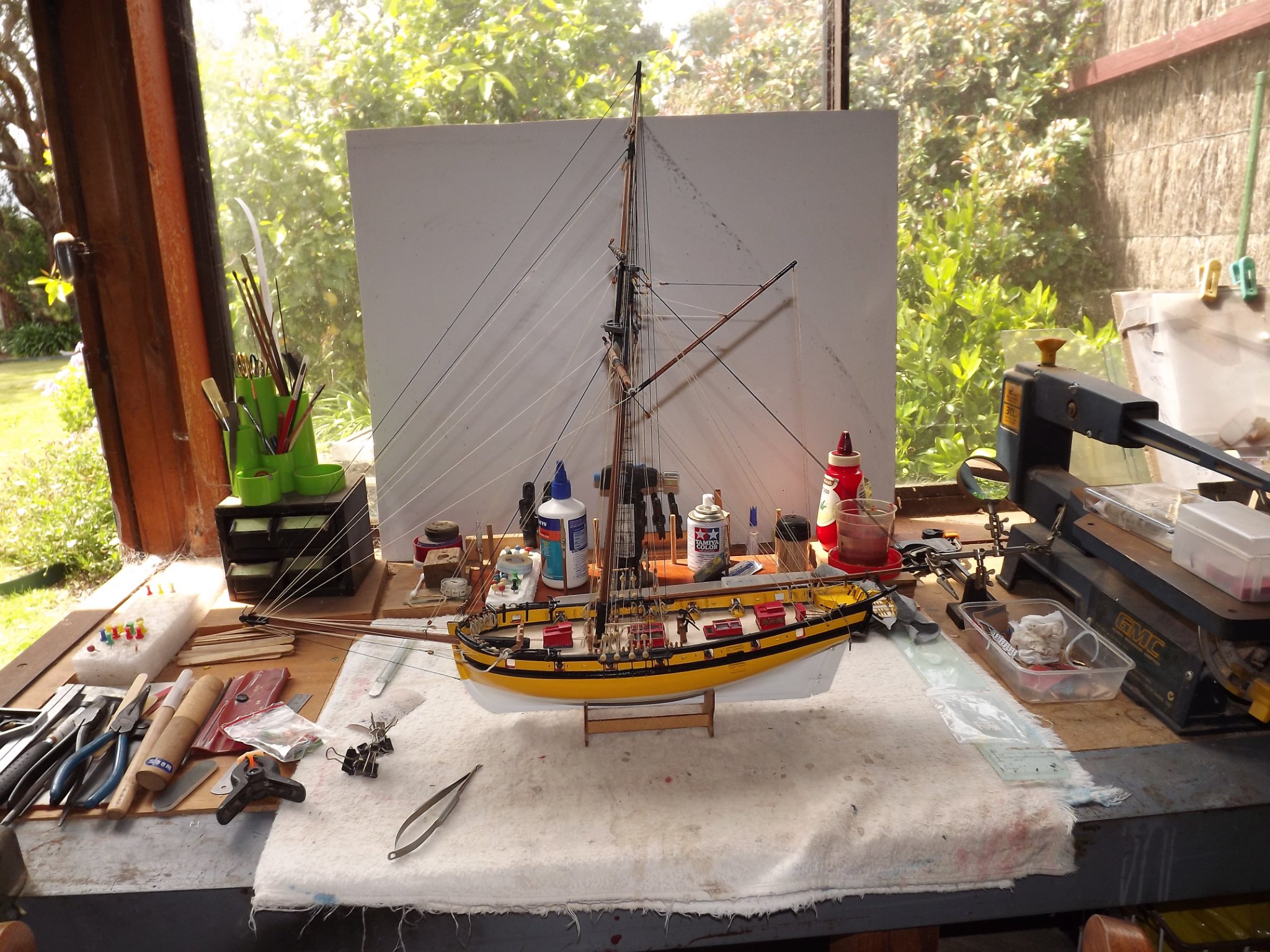
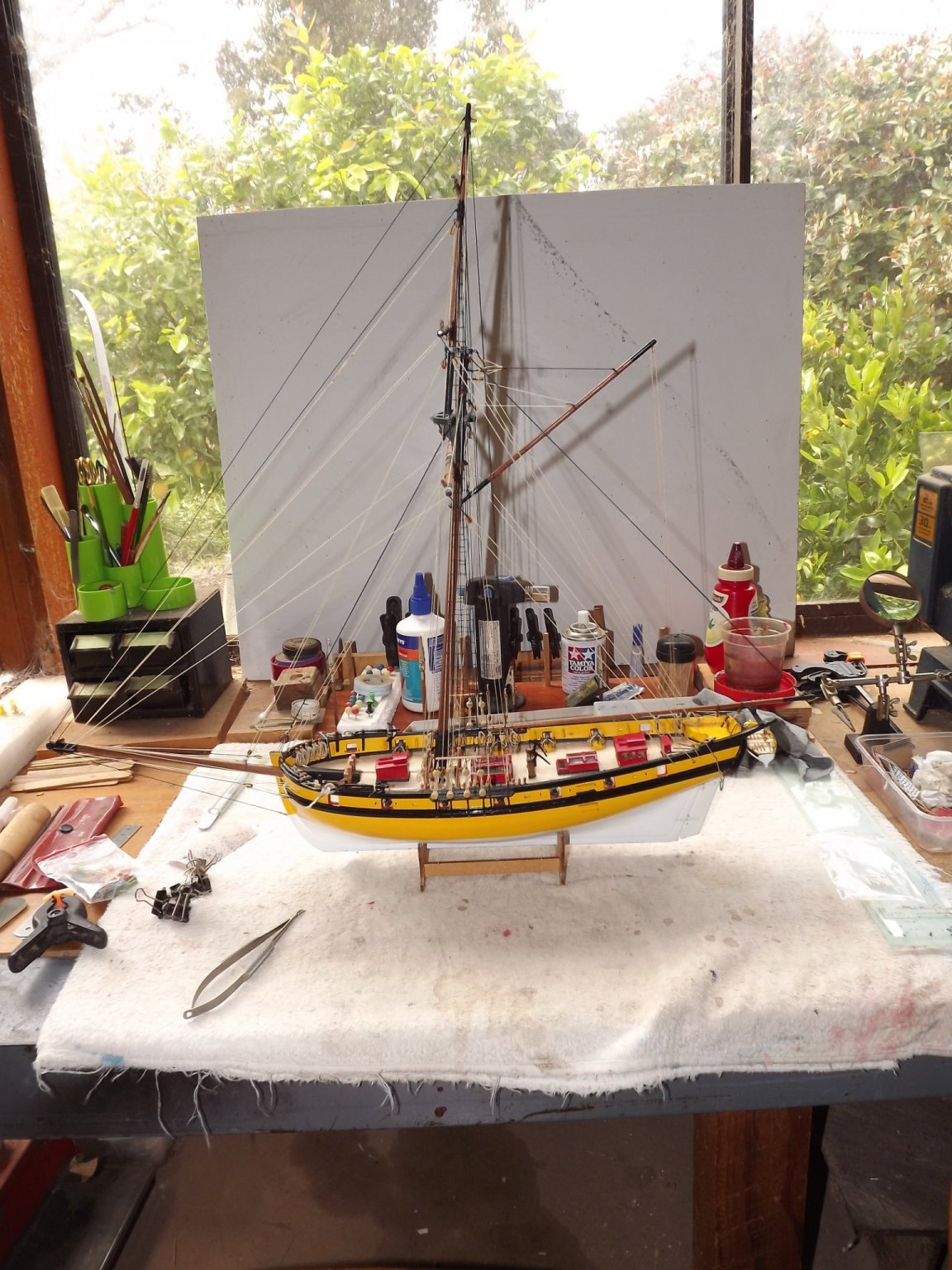
Thanks for the nice comments. As for the stand - it's an old one that I use when building as it fits most hull shapes but I will be making one myself as the supplied one just doesn't sit right. I'm not adding sails as I feel that the supplied ones aren't convincing enough and my skills aren't such that I can make them from scratch. Still got the case to make and one or two little bits to tidy up but otherwise that's it. I had a fair bit of trouble interpreting the rigging plans supplied and eventually reverted to Petersson's "Rigging fore and aft craft" for help, so what you see isn't quite as proposed. Rick
- 110 replies
-
- 1
-

-
- le renard
- artesania latina
- (and 1 more)
-
Love the dinghy, particularly the rope bumper. I chose to provide two seats rather than the single that you've provided. I've finished mine after a reasonable tussle with the rigging, eventually examining photos of the replica, models of le Cerf and various American cutters of that period as the French rigging seemed to compare with the American style rather than British navy. Anyway here are a few (bad) shots of the finished product. Rick


- 110 replies
-
- 9
-
-

-

-
- le renard
- artesania latina
- (and 1 more)
-
Long time since my build but if I recall correctly I used Lego blocks as squares for the bulkheads and transom. Nice and square and they fit neatly between keel and bulkheads. Have fun with it. 😄 Rick
-
Heads up for you - if you haven't already I'd dump the furry rigging thread AL supply and change to one of the others. I use mainly Amati, it's much better quality without any of the fluff that the AL stuff has. I'm using a combination of 1 mm black for the main stay, .5 mm and .1 mm in both black and natural for the balance of the standing and running rigging. Looks more proportional to me. Rick
-
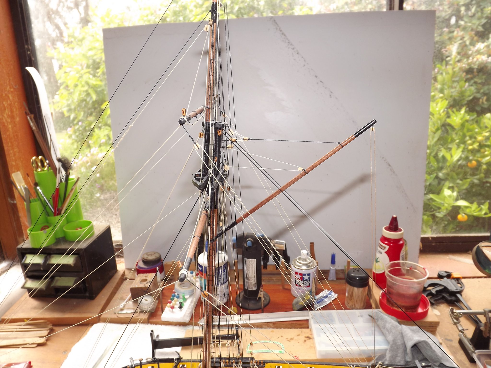
I'm thinking I should let you get ahead of me for a while then I can check with you for instruction errors/omissions. 😉 I'm just starting on the masts already I've one error, but at least it isn't hard to fix. Main mast requires the top to be painted black for 62 mm, the only trouble is that the cheeks fitted under the "crows nest" are 26 mm long which added to the 52 mm tip of mast to "crows nest" isn't the 62 mm indicated on the instructions!! So it needs 80 mm of black to work properly. The next bit is just personal preference. I can't see that the shrouds on the top mast would be tied directly to the mast without anything preventing them slipping down as they expand/contract with the weather, so I've provided a shoulder to loop them over, a little delicate rough carving it but I got there. I'll fully dress the masts before fixing them in place and I'll probably just use the various stays to hold the main mast in place rather than glue it as I find this just as effective with no fear of it moving whilst the glue sets. Rick
- 110 replies
-
- 2
-
-
- le renard
- artesania latina
- (and 1 more)
-
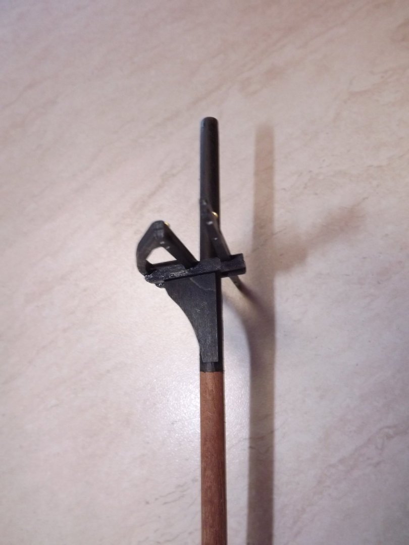
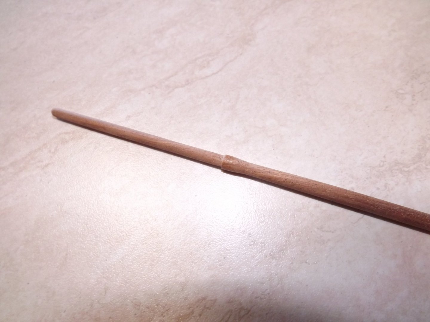
I based my thoughts on the traveller on a number of cutters built during the appropriate period, this link gives a close-up of the bowsprit for le Cerf a slightly larger French cutter of a similar period. https://ancre.fr/en/monograph/34-monographie-du-cerf-cotre-1778.html . I agree the bowsprit does retract but probably no more than the length of the squared off section, however as my experience with sailing is in a negative value I can only look and guess based on what seems to me to be the simplest solution. 😉 There is one item I've added and that's the bilge pumps which you may also see in this link. As there don't appear to be any set dimensions for these pumps mine do vary somewhat from the illustrated ones (found after I'd built them) but at least they do help with deck furniture. Rick 🙂
-
Quick "Heads Up". Have you looked at the rigging book yet? Not the best one I've ever seen and there appear to be a number of short cuts being used. It seems to be missing the traveller with its in-haul and out-haul. As far as I can see this has just been replaced by a block wired to the end of the bowsprit, so it you're near fitting it you may want to consider constructing the traveller ring etc. before fitting the end ring on the bowsprit. Do you have any other books giving basic rigging for this type of ship? It will help interpret these instructions. Rick
-
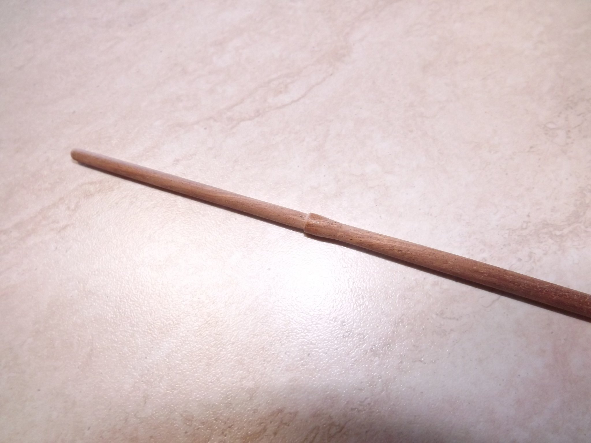
You're welcome to use any ideas I put up - that's what the forum is all about! With my bowsprit I've made a separate octagonal section that I intended fitting to a shortened dowel (after tapering). Before I go down that route however I think I'll try your method. By the way, that's a lovely paint job you've done, talking of which I'm puzzled by the suggestion that gun port lids be painted red on the inner face. This will end up with a rather odd checkerboard pattern on the inner face of the gunwales, just doesn't make sense to me. I'm actually considering leaving the lids off as 99% of all cutters of this size (and bigger) have open ports check this as a sample https://www.amarsenal.be/fr/membres-modeles/helmut-dejardin/le-cerf . Rick
- 110 replies
-
- 1
-
-
- le renard
- artesania latina
- (and 1 more)
-
Welcome Andrew - beginning to look like we have enough Aussies to set up a sub-forum by now! Rick (Another Locked Down Victorian) 🙂
-
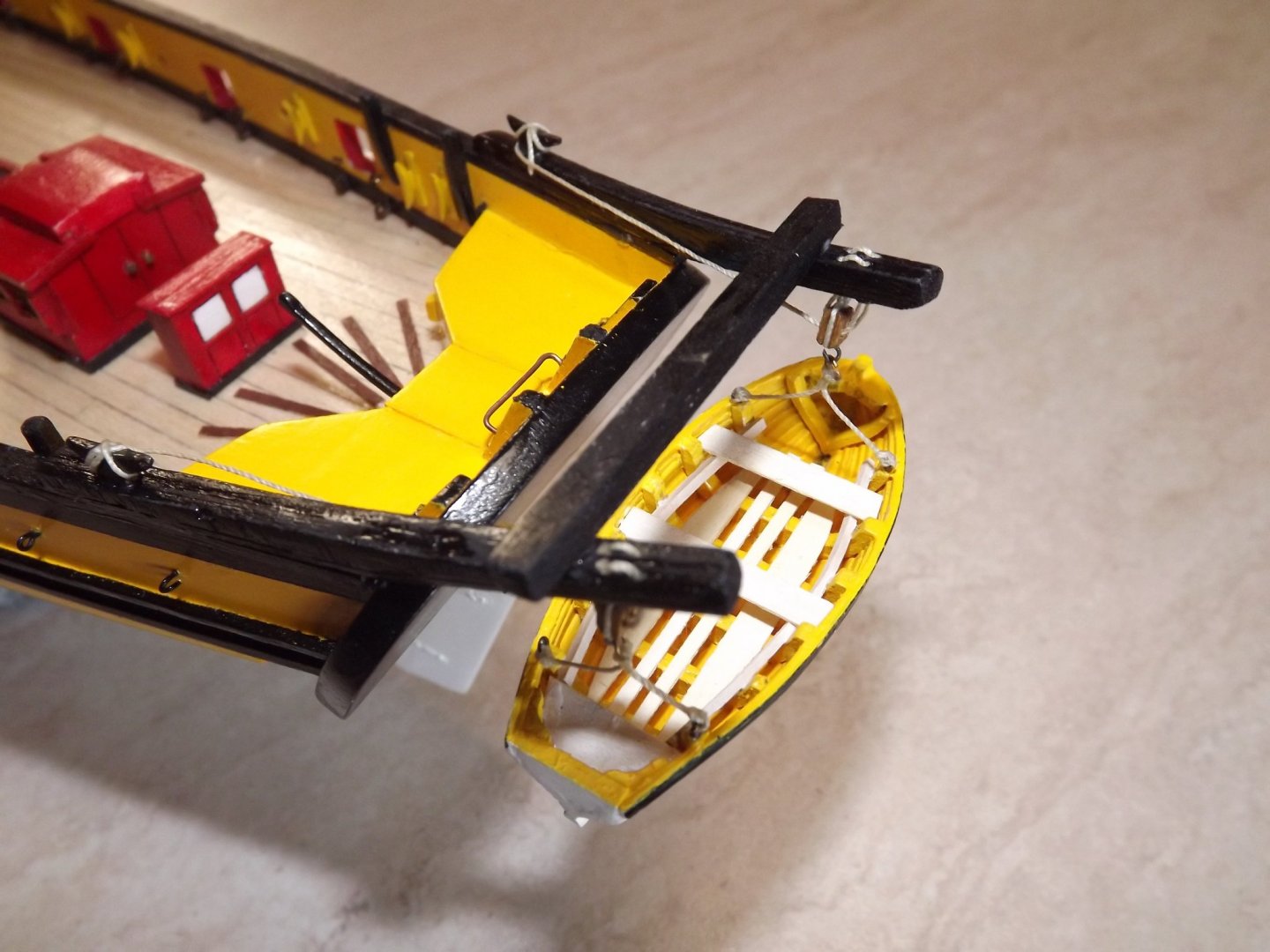
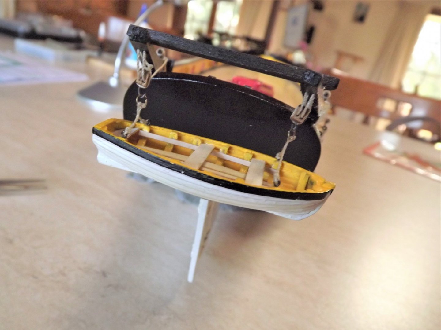
... and my revised boat davits and boat. The davits and cross bar were doubled in thickness 5mm removed from the davits length and the holes for the block and tackle were set back 5 mm from the end. This is all based on a couple of photos I found on line for the replica and make more sense than the kit version. The boat is also built as a clinker design. Rick
- 110 replies
-
- 2
-
-
- le renard
- artesania latina
- (and 1 more)
-
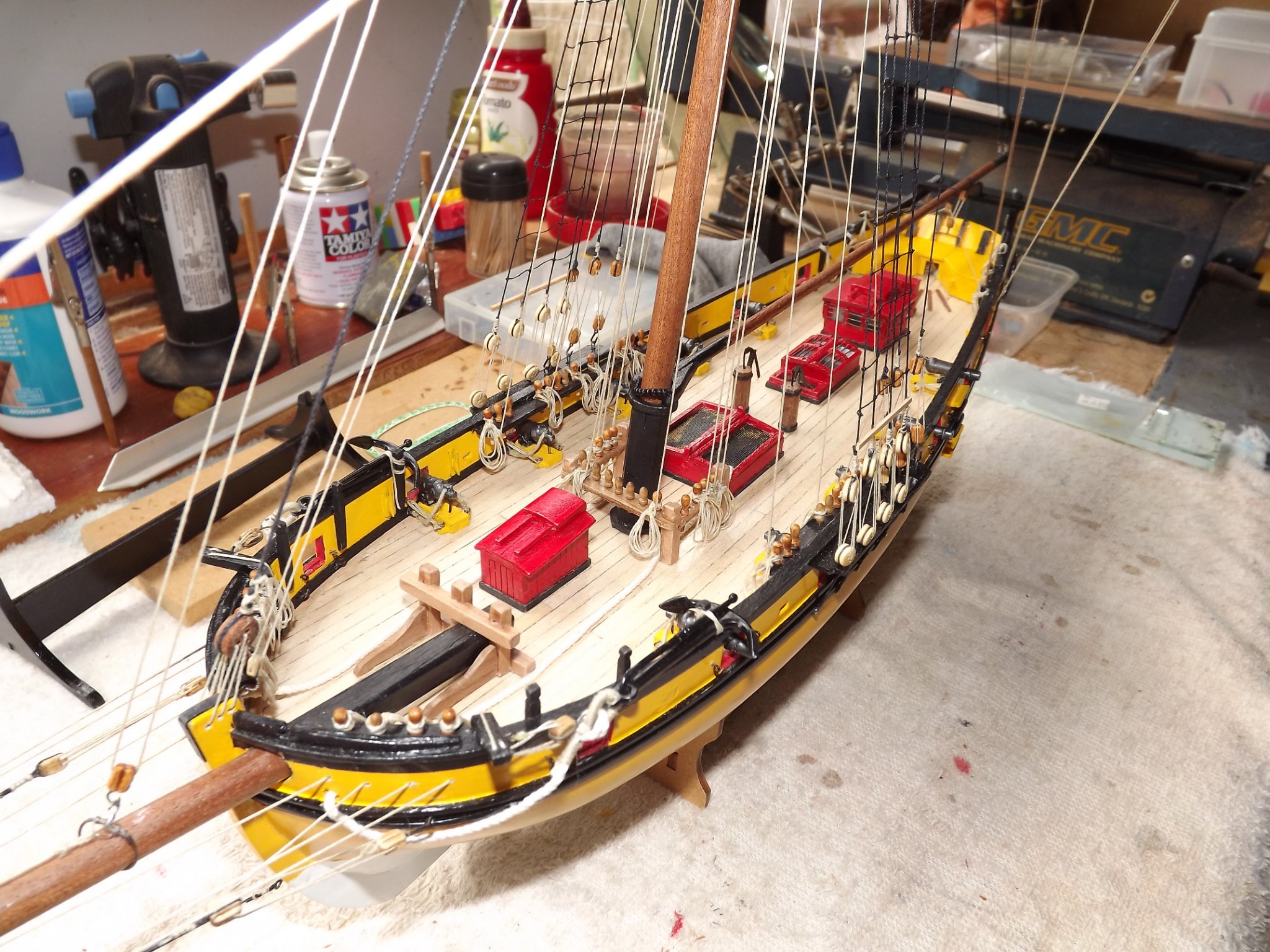
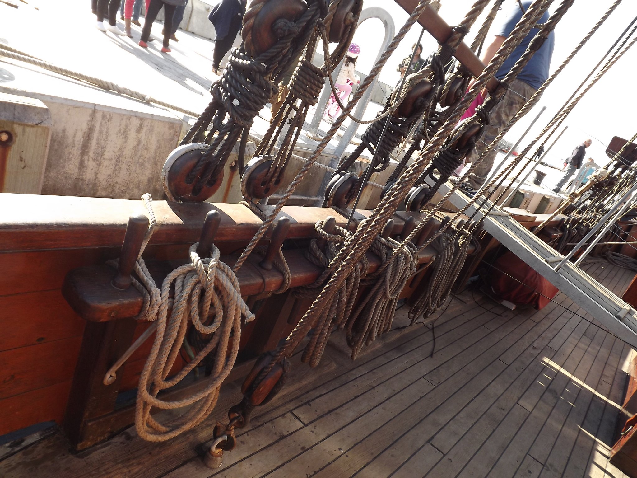
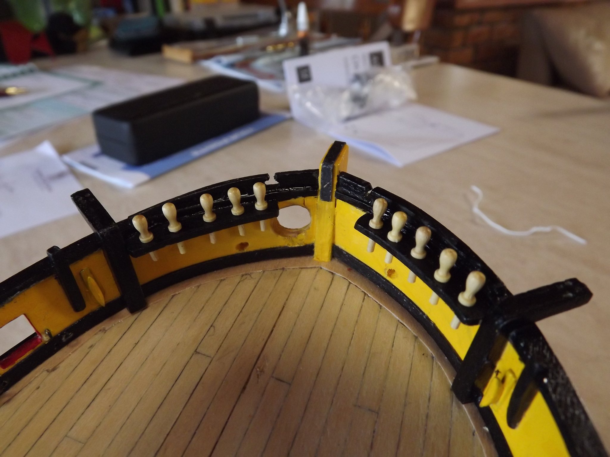
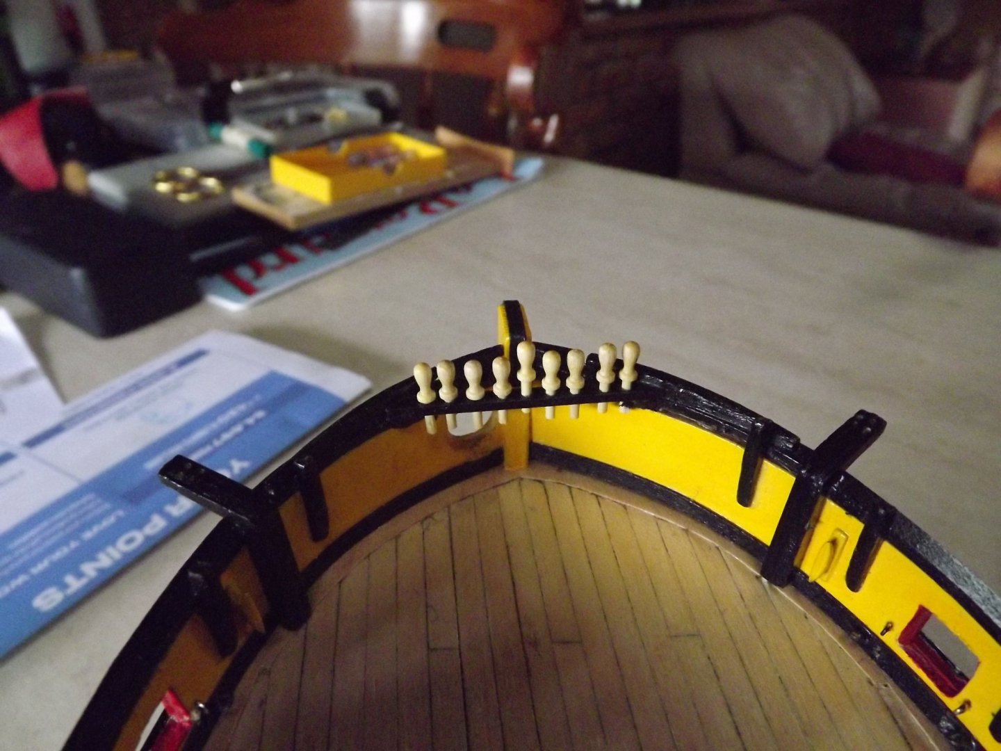
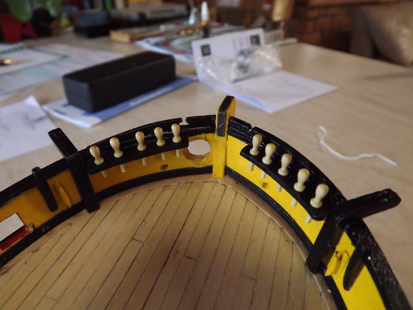
Whilst I'm re-writing the instructions I've made an executive decision and gone down a different route for the fore fife rail. This is an illustration of belaying pin spacing on a working replica ship of the same period. This is the fife rail with pins fitted as per kit instructions. Very close together, I am using slightly larger pins but even with the metal ones supplied it was still to tight. So off came the original rail, a quick look around the internet and I've come up with an acceptable solution based on other contemporary models. You'll also notice two hawse holes where I intend bringing the anchor cable onto the deck rather than through the hull into what would probably be crew quarters. In the replica they must have had an electric winch below decks, whereas originally the anchor would have been been hoist by either windlass or block and tackle as a best guess. The next interesting build will be the octagonal section on the bowsprit - as it stands I can't see that their instructions will work. Rick

- 110 replies
-
- 5
-
-
- le renard
- artesania latina
- (and 1 more)
-
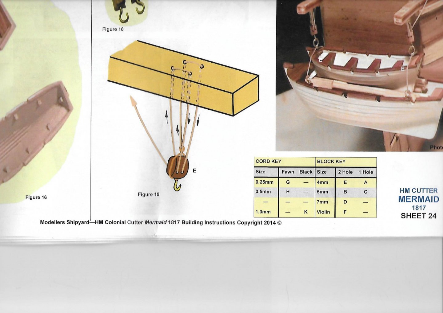
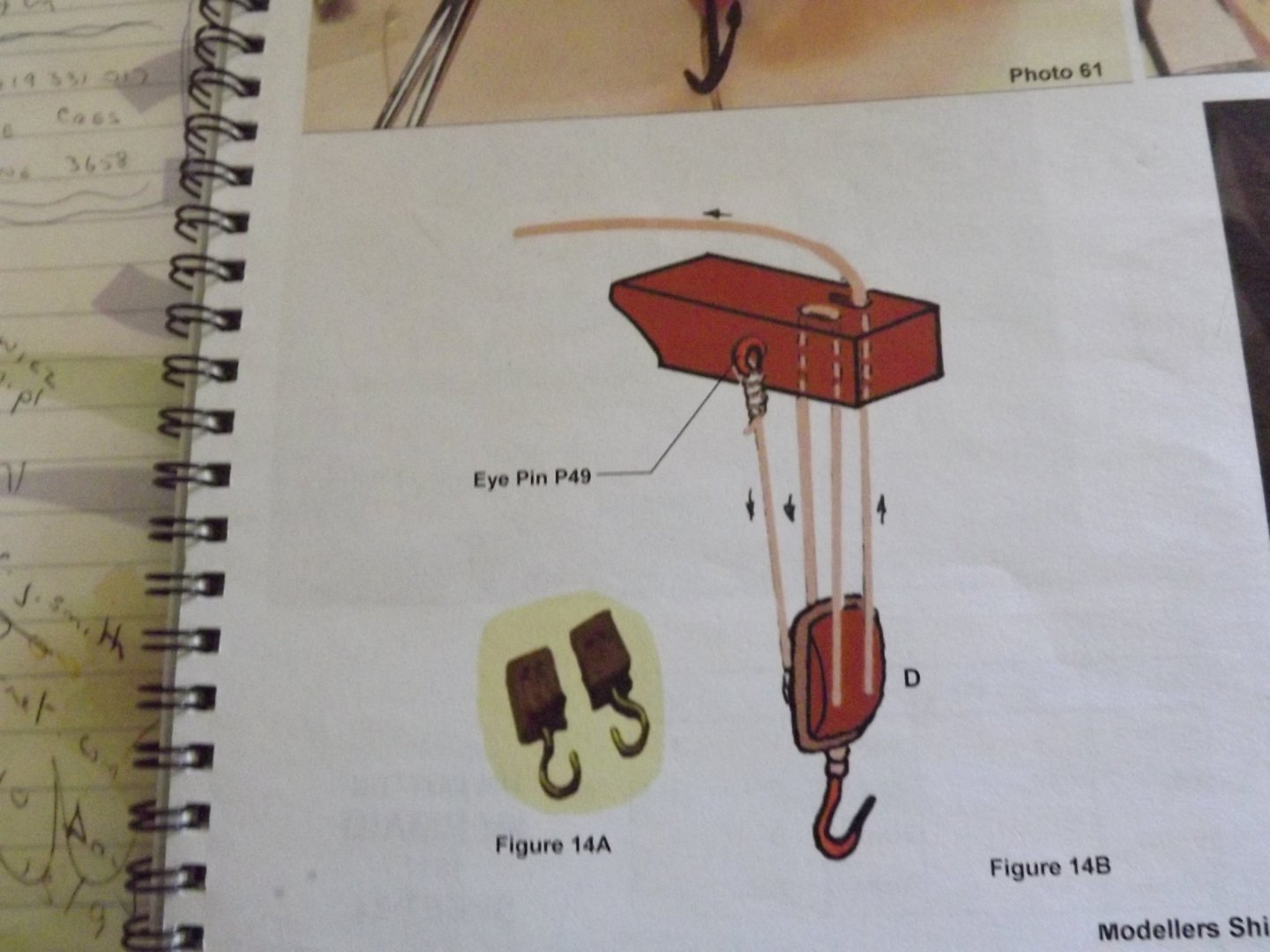
Remember that the davits holding the boat will hide some "mis-fitting" of the cap rail. However as with the catheads these will need to be doubled in thickness. Currently the kit asks you to believe that the ship's boat is held safely by a couple of 2 metre lengths of timber 10 cm sq. Here's my version. ... and here's an illustration of a more realistic method of rigging the lifts. Similar to the catheads rigging. I've been looking at the various photos of the replica and it seems that the arms should also be shorter as the boat when hoist appears very close to the transom - still thinking about that item. Rick

- 110 replies
-
- 2
-
-
- le renard
- artesania latina
- (and 1 more)
-
Much better idea - I've a nasty little problem where my cap rail doesn't sit neatly with the transom as the latter was fitted first and ended up positioned a fraction low. 👿 Rick
-
... and how long before all the surfaces are covered again! 😉 I never seem able to keep my work area tidy for more than five minutes. Rick
- 110 replies
-
- 1
-
-
- le renard
- artesania latina
- (and 1 more)
-
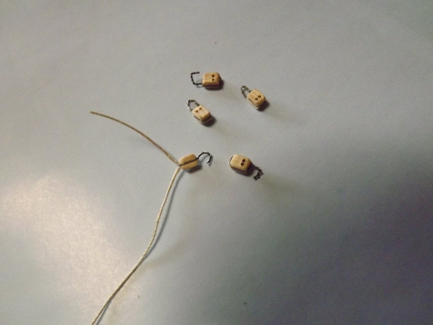
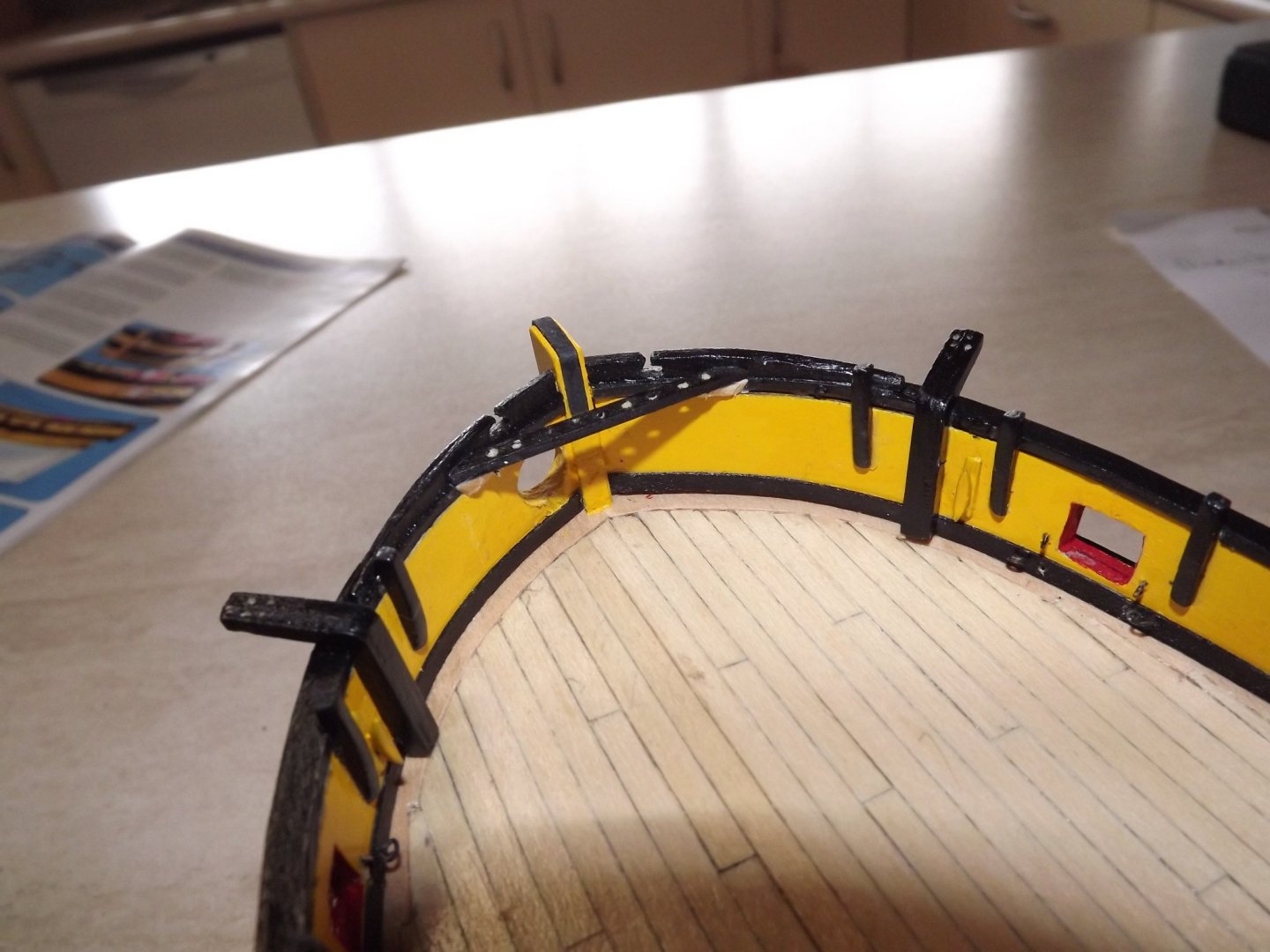
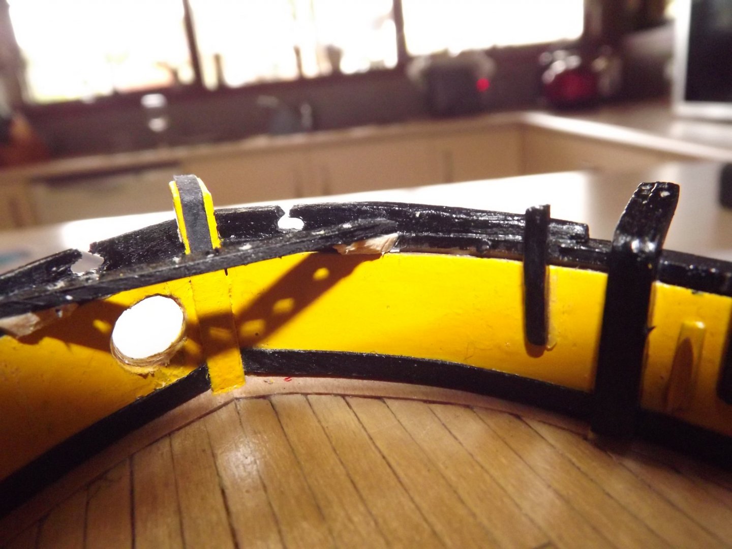
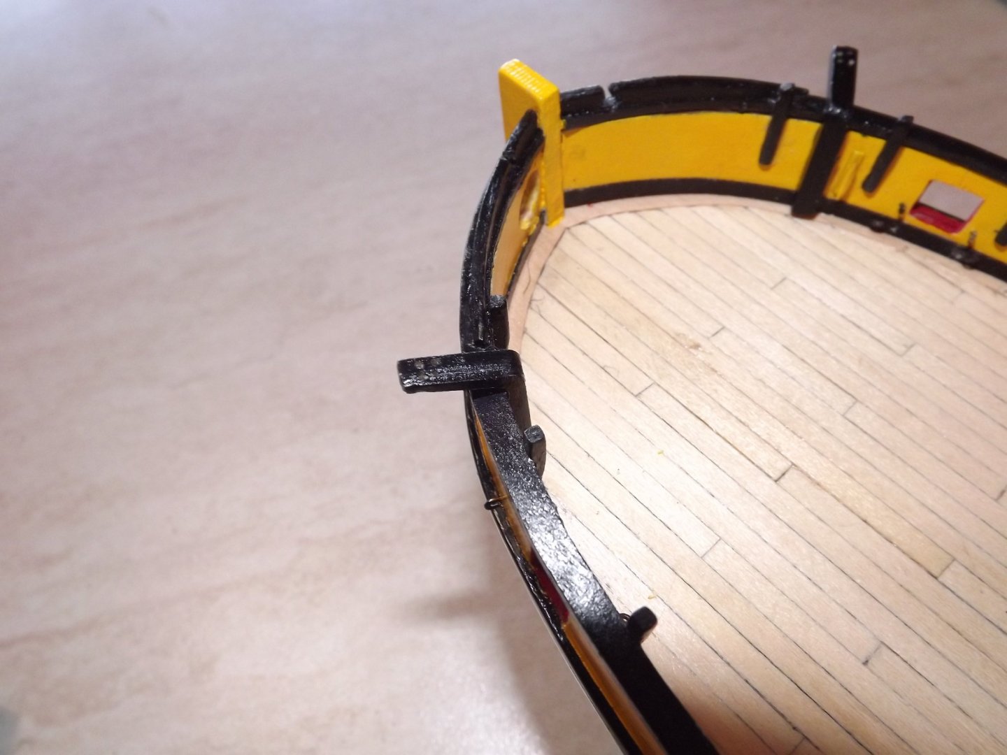
I'm working on the prow and have attached the belaying pin rail but had to add a brace each end as there was insufficient room on the capping rail to attach according to the plans. Note also the reinforcing bar is running prow to stern not port to starboard. Just about every ship of this size I've seen has had the mainstay braced by lines through a block or heart down to 3 or 5 holes in the prow not to a single pin. Tip here use a heavy black cartridge paper soaked in PVA glue easier to work and looks just like a metal reinforcing strip. Given the pressures involved I prefer to use this system. I've also started on the blocks for the carronade tackle, look a little rough close-up but when finished they should be reasonable. Rick

- 110 replies
-
- 1
-
-
- le renard
- artesania latina
- (and 1 more)
-
Looking good there - it's surprising what a little paint will disguise but from what I can see I don't think you need worry about them not being presentable. We're all going a little stir crazy at the moment but this sort of occupation does help keep us sane (sort of). Rick 🙂
-
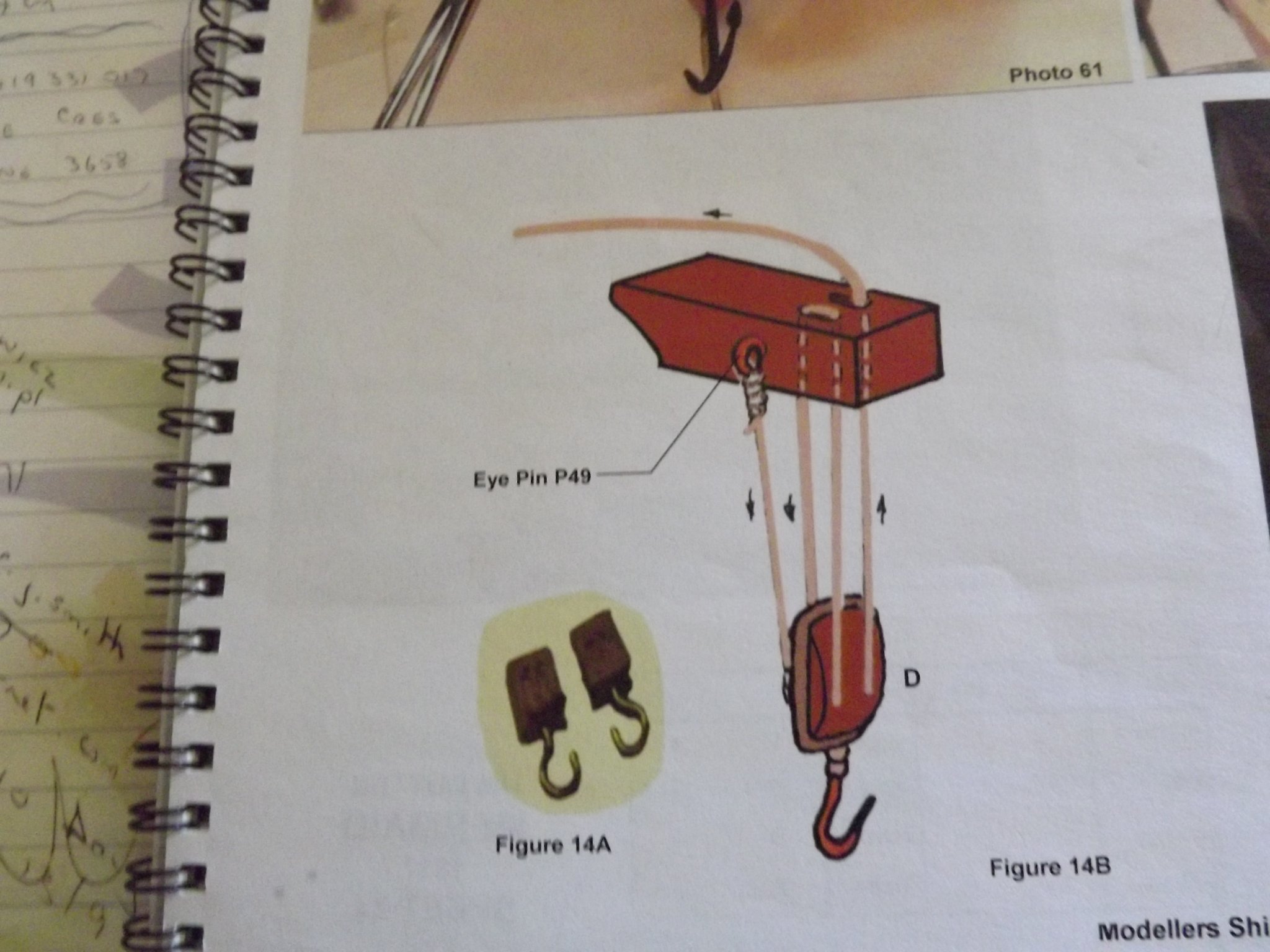
There's not a lot out there that I can find, however both these secondary sources state that the cutter is pierced for 14 guns. 10 carronades (as supplied) plus 4 4lb guns see https://www.modelboats.co.uk/news/article/le-renard/602 and http://renard.dechorgnat.com/artillerie.html (Google will translate this page). I only had a couple of correct size cannon spares so the captain must have a couple of them stowed below for some reason 😉. Catheads - really bad design, way too thin and poorly set up for the lifting rope. I've doubled the thickness and drilled the top with four holes to represent pulley wheels as per this illustration. Next is the binnacle which I've fitted further from the companionway so that the doors on the companionway can actually open! I've chosen to treat the upper sections as if they were glassed in - I can't see why they would be cupboard type if the helmsman needed to see a compass. I may also add tie downs to the binnacle as it's my understanding that this would be stowed below in battle (fewer splinters to fly around). I'm also not happy with the length of the bars on th deck to steady the helmsman's feet - they look disproportionately long to me. My 3mm blocks arrived today so next job it to sand the edges down to give a rounded appearance then construct hooks and add rope - eyestrain here I come! Rick
- 110 replies
-
- 3
-
-
- le renard
- artesania latina
- (and 1 more)
-
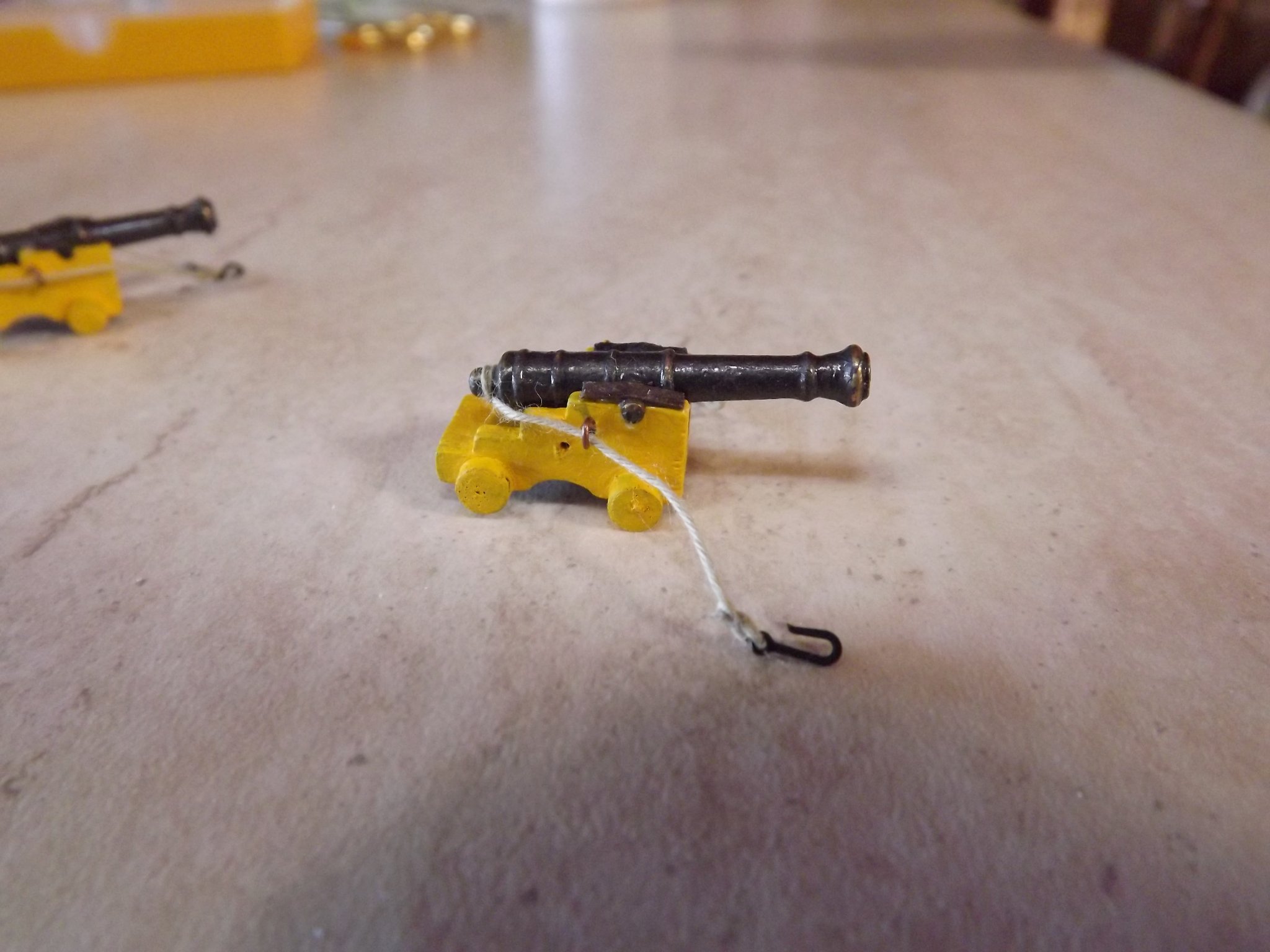
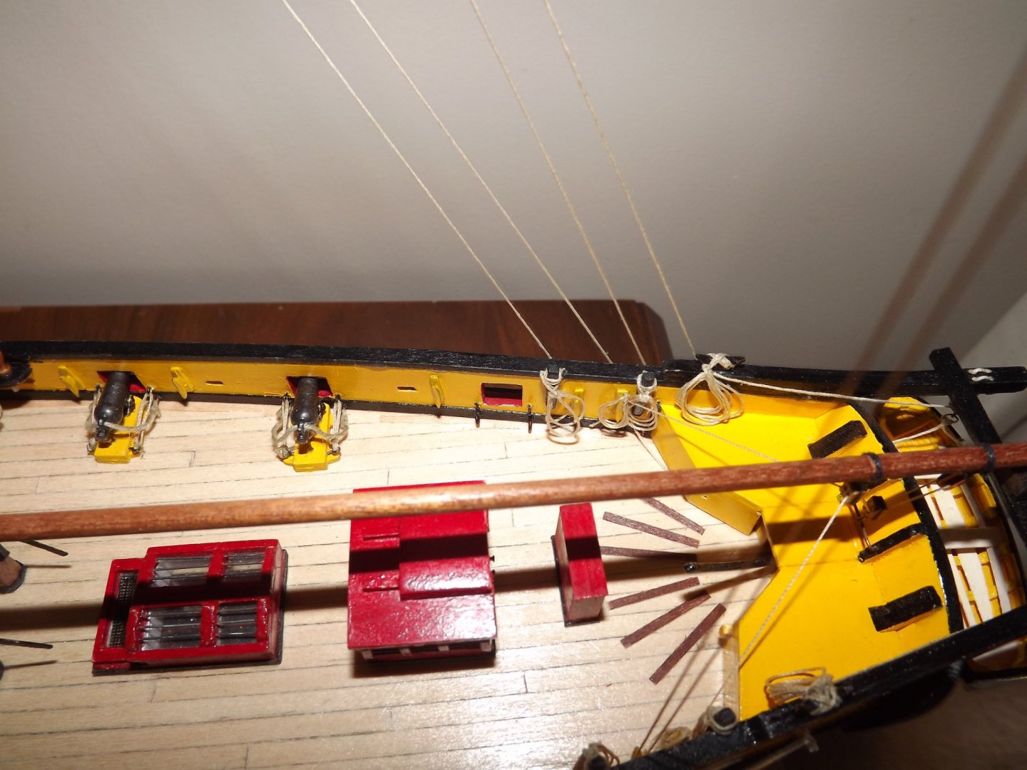
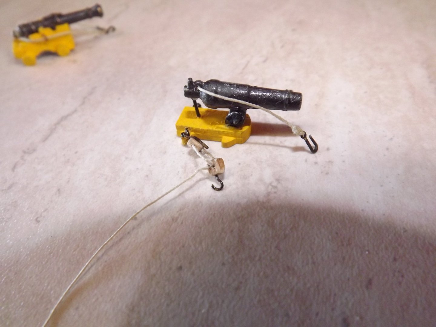
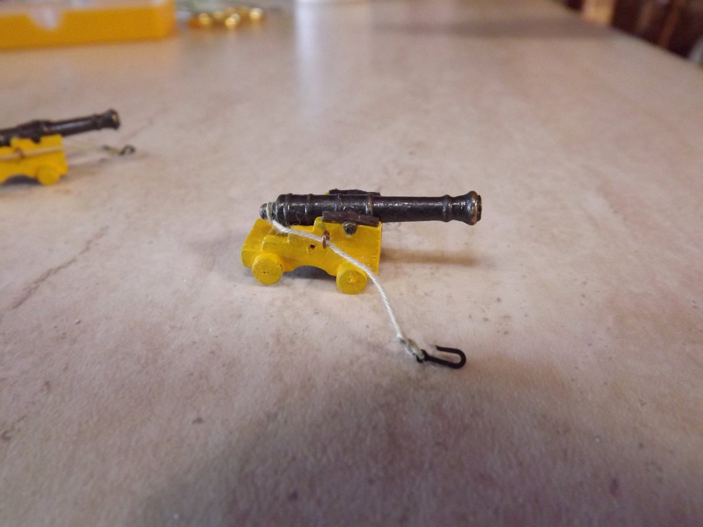
When you come to fitting the gun tackle you may want to try smaller blocks than those provided. I've used 3 mm and also added the restraining rope to the carronade itself. Still not as good as I'd like but I just can't handle 2 mm blocks! I've also dug up a pair of 6lb cannon left over from another build and will add these at the prow. I haven't completed the tackle yet as I'm waiting on a mail order - we're in complete lockdown so it's mail or nothing at the moment. Rick
- 110 replies
-
- 4
-
-
- le renard
- artesania latina
- (and 1 more)
-
Have you offered up the carronades to see that they all clear the ports? I found that I'd slipped the gunwales down a fraction and the barrels of the central two guns fouled the ports and needed the slide base sanded down a little to allow them to fit neatly. Rick
-
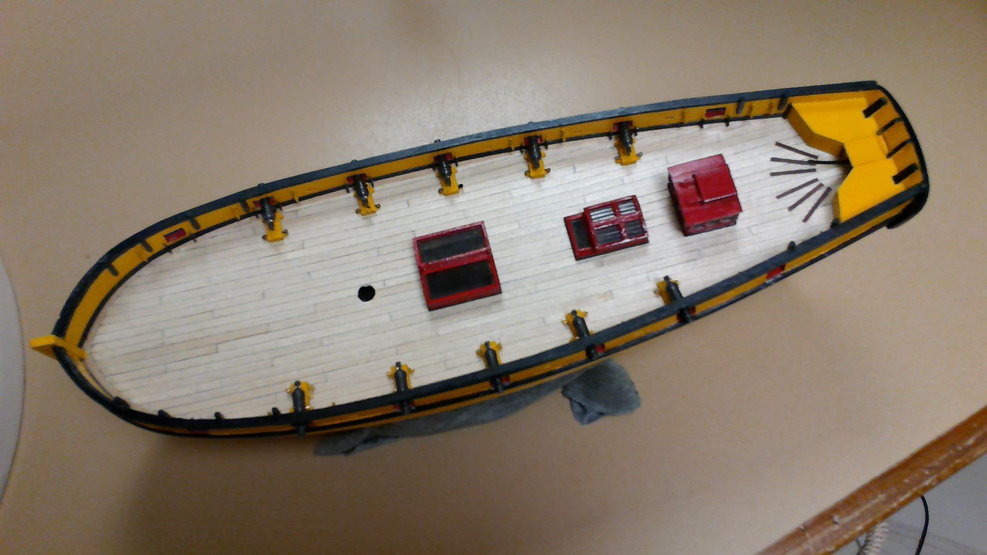
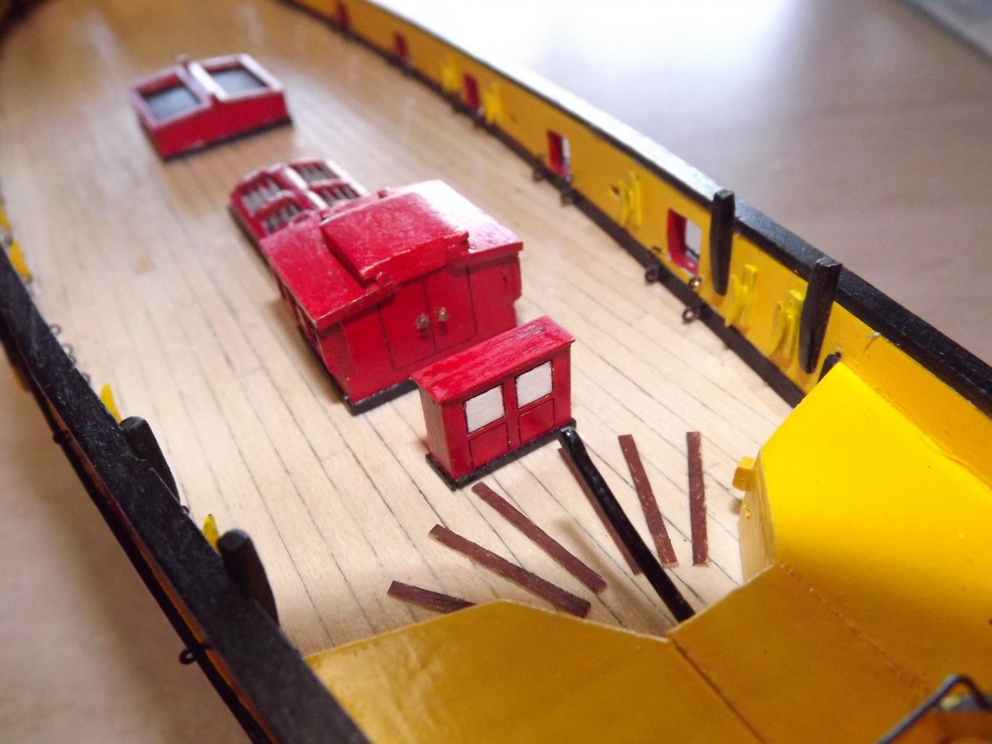
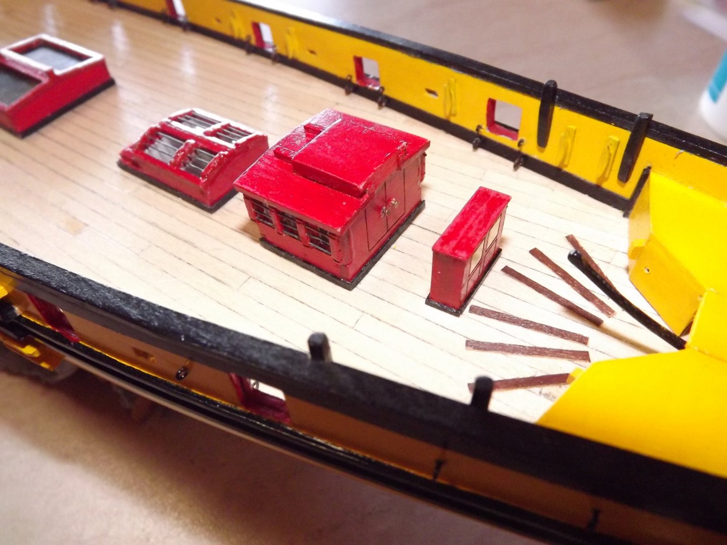
Deck layout I'm using. A number of items have been omitted as they appear to be requirements on the replica. Items at the bow not yet installed as a couple of 4lb cannon need to be built and space needs to be checked.

- 110 replies
-
- 7
-
-
- le renard
- artesania latina
- (and 1 more)
-
Inspired guess here. Block/wedge under the keel, then ropes from the eyebolts in the gunwales that would secure the cannon/carronades, over the hull and across to eyebolts along or near to the centreline. These latter should be there anyway to pull the cannon inboard. Rick
-
I recall that when I was researching my version I saw a note somewhere that one of the boats was "broken down" and stored below. However I can't now recall where that was. By the way the instructions with the kit are not the best with the deck furnishings not positioned as per King's sketch and in particular the topsail yard should be "flying" and the halyards for the gaff also not per the sketch. There are some other problems but I can't remember them at the moment. 😞 Rick
-
Tip of the day. Cut the hole for the rudder (page 41), BEFORE fitting assembly K (page 23). Less chance of splitting decking planks or finding the rudder post binds against the transom. Not saying this may have happened to me , however ... Rick 🙂
- 110 replies
-
- 1
-
-
- le renard
- artesania latina
- (and 1 more)
-
Quick tip for you. If you haven't put the bars in your deck furnishings yet, get a long .6 mm or .75 mm drill and run it through the holes that the bars fit in. I found that the holes didn't line up perfectly and had problems fitting the bars until I ran the drill through and effectively lined them up. As for the bars themselves I just heated them up til they glowed then cooled them, it gave an authentic iron colour without having to paint! Should add that I'm using a roll of .75 mm steel wire instead of the supplied item - you can afford to make a lot of mistakes cutting correct lengths when you've got 10 metres of it! I'm a couple of steps ahead of you at the moment having just finished the hull painting. Rick
- 110 replies
-
- 1
-
-
- le renard
- artesania latina
- (and 1 more)